1993 DODGE TRUCK oil type
[x] Cancel search: oil typePage 712 of 1502
•
5.9L
(DIESEL)
ENGINE
9 -
107
5.9L
(DIESEL)
ENGINE
SERVICE
PROCEDURES
INDEX
page
Camshaft
127
Crankshaft
138
Cylinder
Block
129
Cylinder
Head
113
Engine
Assembly
. 109
Engine
Front
Mounts
(Insulators
/
Brackets)
... 107
Engine
Rear Support
108
Gear
Housing
/
Cover
122
General
Information
107
Oil Cooler Element
/
Gasket
. 149
Oil
Filter
148
page
Oil
Filter
Bypass
Valve
. 148
Oil Pan
/
Suction Tube
146
Oil Pressure Regulator Valve
/
Spring
148
Oil Pump
146
Piston
/
Connecting
Rod
Assembly
134
Rocker
Levers
/
Push
Rods
112
Specifications—5.9L Diesel Engines
151
Tappet
125
Timing
Pin
123
Valve Clearance
Adjustment
...............
121
Valves
and
Valve Springs
116
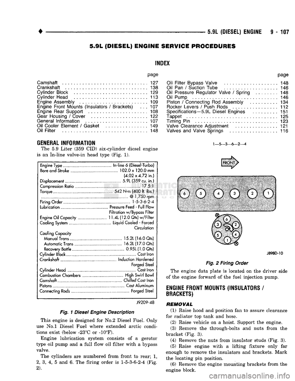
GENERAL INFORMATION The
5.9
Liter
(359 CID)
six-cylinder diesel engine
is
an
In-line valve-in head type
(Fig. 1).
Fig.
1
Diesel
Engine
Description
This engine
is
designed
for No.2
Diesel Fuel. Only
use
No.l
Diesel Fuel where extended arctic condi
tions exist (below -23°C
or -10°F).
Engine lubrication system consists
of a
gerotor
type
oil
pump
and a
full flow
oil
filter with
a
bypass valve.
The cylinders
are
numbered from front
to
rear;
1,
2,
3, 4, 5 and 6. The
firing order
is
1-5-3-6-2-4
(Fig.
2).
J898D-10
Fig.
2
Firing Order
The engine data plate
is
located
on the
driver side
of
the
engine forward
of the
fuel injection pump.
ENGINE FRONT MOUNTS (INSULATORS
/
BRACKETS)
REMOVAL (1) Raise hood
and
position
fan to
assure clearance
for radiator
top
tank
and
hose.
(2) Raise vehicle
on a
hoist. Support
the
engine.
(3) Remove
the
through-bolts
and
nuts from
the
bracket
(Fig. 3).
(4) Remove
the
nuts from insulator studs
(Fig. 3).
(5) Raise engine with
a
lifting fixture only
far
enough
to
remove
the
insulators
and
brackets. Mark
the locating
pin
position.
(6) Remove
the
engine mounting brackets from
the
engine block.
Engine Type
In-line
6
(Diesel-Turbo)
Bore and Stroke 102.0 x 120.0 mm
(4.02x4.72 in.)
Displacement 5.9L (359 cu.
in.)
Compression Ratio 17.5:1
Torque 542 N-m (400 ft. lbs.)
@
1,750 rpm
Firing Order
1-5-3-6-2-4
Lubrication Pressure Feed - Full Flow
Filtration w/Bypass Filter
Engine Oil Capacity
11.4L
(12.0 Qts) w/Filter
Cooling System Liquid Cooled
-
Forced
Circulation
Cooling Capacity
Manual Trans 15.2L (16.0 Qts)
Automatic Trans 16.2L (17.0 Qts)
Recovery Bottle 0.95L(1.0Qts)
Cylinder Block.... Cast Iron
Crankshaft Induction Hardened
Forged Steel
Cylinder Head Cast Iron
Combustion Chambers High Swirl Bowl
Camshaft.... Chilled Cast Iron
Pistons Cast Aluminum
Connecting Rods Forged Steel
J9209-48
Page 742 of 1502
•
5.9L (DIESEL) ENGINE
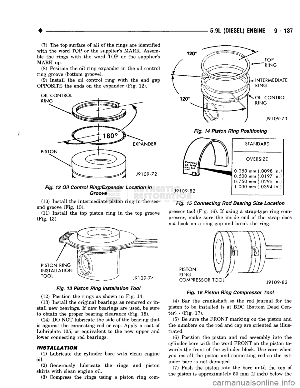
9 - 137 (7) The top surface of all of the rings are identified
with the word TOP or the supplier's MARK. Assem
ble the rings with the word TOP or the supplier's MARK up.
(8) Position the oil ring expander in the oil control
ring groove (bottom groove). (9) Install the oil control ring with the end gap
OPPOSITE the ends on the expander (Fig. 12). OIL CONTROL
RING
PISTON EXPANDER
J9109-72
Fig.
12 Oil Control
Ring/Expander
Location in
Groove
(10) Install the intermediate piston ring in the sec
ond groove (Fig. 13).
(11) Install the top piston ring in the top groove
(Fig. 13). PISTON RING
INSTALLATION
TOOL J9109-74
Fig.
13
Piston
Ring
Installation
Tool (12) Position the rings as shown in Fig. 14.
(13) Install the original bearings as removed or in
stall new bearings. If new bearings are used, be sure
to obtain the proper bearing clearance (Fig. 15). (14) DO NOT lubricate the side of the bearing that
is against the connecting rod or cap. Apply a coat of
Lubriplate 105, or equivalent to the new upper and
lower connecting rod bearings.
INSTALLATION
(1) Lubricate the cylinder bore with clean engine
oil.
(2) Generously lubricate the rings and piston
skirts with clean engine oil. (3) Compress the rings using a piston ring com- TOP
RING
INTERMEDIATE
RING
OIL CONTROL
RING
J9109-73
Fig.
14
Piston
Ring
Positioning
STANDARD
J9109-82
OVERSIZE
0.250 mm (.0098 in.
0.500 mm (.0197 in.
0.750 mm (.0295 in. 1.000 mm (.0394 in.
Fig.
15
Connecting
Rod Bearing
Size
Location pressor tool (Fig. 16). If using a strap-type ring com
pressor, make sure the inside end of the strap does
not hook on a ring gap and break the ring.
PISTON
RING
COMPRESSOR TOOL J9109-83
Fig.
16
Piston
Ring
Compressor
Tool (4) Bar the crankshaft so the rod journal for the
piston to be installed is at BDC (Bottom Dead Cen
ter) - (Fig. 17).
(5) Be sure the FRONT marking on the piston and
the numbers on tlie rod and cap are oriented as illus
trated.
(6) Position the piston and rod assembly into the
cylinder bore with the word FRONT on the piston to
wards the front of the cylinder block. Use care when
you install the piston and connecting rod so the cyl inder bore is not damaged.
(7) Push the piston into the bore until the top of
the piston is approximately 50 mm (2 inch) below the
Page 751 of 1502
9
- 148 5.9L
(DIESEL) ENGINE
• Make sure the idler gear pin is installed in the lo
cating bore in the cylinder block. (2) Install the pump. Tighten the oil pump mount
ing bolts in two steps and in the sequence shown (Fig. 2).
• Step
1—Tighten
to 5 N«m (44 in. lbs.) torque.
• Step 2-Tighten to 24 N*m (18 ft. lbs.) torque. (3) The back plate on the pump seats against the
bottom of the bore in the cylinder block. When the
pump is correctly installed, the flange on the pump will not touch the cylinder block.
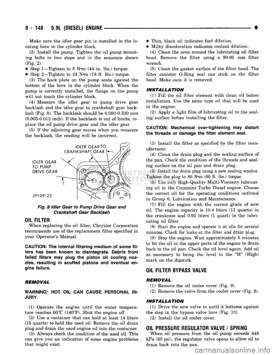
(4) Measure the idler gear to pump drive gear
backlash and the idler gear to crankshaft gear back lash (Fig. 8). The backlash should be 0.080-0.330 mm (0.003-0.013 inch). If the backlash is out of limits, re
place the oil pump drive gear and the idler gear.
(5) If the adjoining gear moves when you measure
the backlash, the reading will be incorrect.
Fig.
8
idler
Gear to
Pump
Drive Gear and Crankshaft Gear
Backlash
OIL FILTER
When replacing the oil filter, Chrysler Corporation
recommends use of the replacement filter specified in
your Operator's Manual.
CAUTION:
The
internal filtering medium
of
some
fil
ters
has
been known
to
disintegrate. Debris from
failed filters
may
plug
the
piston
oil
cooling noz
zles,
resulting
in
scuffed pistons
and
eventual
en
gine
failure.
REMOVAL
WARNING:
HOT OIL CAN
CAUSE PERSONAL
IN
JURY.
(1) Operate the engine until the water tempera
ture reaches 60°C (140°F). Shut the engine off.
(2) Use a container that can hold at least 14 liters
(15 quarts) to hold the used oil. Remove the oil drain
plug and drain the used engine oil into the container.
(3) Always check the condition of the used oil. This
can give you an indication of some engine problems
that might exist. • Thin, black oil indicates fuel dilution.
• Milky discoloration indicates coolant dilution.
(4) Clean the area around the lubricating oil filter
head. Remove the filter using a 90-95 mm filter
wrench.
(5) Clean the gasket surface of the filter head. The
filter canister O-Ring seal can stick on the filter
head. Make sure it is removed.
INSTALLATION (1) Fill the oil filter element with clean oil before
installation. Use the same type oil that will be used
in the engine.
(2) Apply a light film of lubricating oil to the seal
ing surface before installing the filter.
CAUTION:
Mechanical over-tightening
may
distort
the threads
or
damage
the filter
element seal.
(3) Install the filter as specified by the filter man
ufacturer. (4) Clean the drain plug and the sealing surface of
the pan. Check the condition of the threads and seal ing surface on the oil pan and drain plug.
(5) Install the drain plug using a new sealing washer.
Tighten the plug to 80 N-m (60 ft. lbs.) torque.
(6) Use only High-Quality Multi-Viscosity lubricat
ing oil in the Cummins Turbo Diesel engine. Choose
the correct oil for the operating conditions outlined in Group 0, Lubrication and Maintenance.
(7) Fill the enginfe with the correct grade of new
oil.
The engine capacity is i0.4 liters (11 quarts) in
the crankcase and 0.95 liters (1 quart) in the lubri cating oil filter. (8) Start the engine and operate it at idle for several
minutes. Check for leaks at the filter and drain plug.
(9) Stop the engine. Wait approximately 5 minutes
to let the oil in the upper parts of the engine to drain
back to the oil pan. Check the oil level again. Add oil as necessary to bring the level to the "H" (High)
mark on the dipstick.
OIL FILTER
BYPASS
VALWE
REMOVAL
(1) Remove the oil cooler cover (Fig. 9). (2) Remove the valve from the cooler cover (Fig. 9).
INSTALLATION (1) Drive the new valve in until it bottoms against
the step in the bypass valve bore (Fig. 10).
(2) Install the oil cooler cover.
OIL PRESSURE REGULATOR VALVE
/
SPRING
When oil pressure from the oil pump exceeds 448
kPa (65 psi), the regulator valve opens to allow oil to
drain back into the pan.
Page 763 of 1502
11
- 4
EXHAUST SYSTEM
AND
INTAKE MANIFOLD
•
SERVICE
PROCEDURES (GASOLINE ENGINES)
INDEX
page
Catalytic
Converters
4
Engine
Exhaust
Manifold
: . . . . 15
Exhaust
Heat
Shields
5
Exhaust
Pipe
4
page
Exhaust
Tailpipe
. 5
Intake Manifold
13
Mufflers
4
EXHAUST PIPE Refer
to
Figs.
1, 4, 5 and 6 for the
following proce
dure.
REMOVAL (1) Raise vehicle
on a
hoist.
(2) Apply penetrating
oil to
bolts
and
clamp nuts.
(3) Remove clamps, supports
and
bolts from
ex
haust pipe.
(4) Remove
the
exhaust pipe.
(5) Clean ends
of
pipes
to
assure mating
of all
parts.
(6) Discard rusted clamps, broken
or
worn supports
and attaching parts. Replace
a
component with orig
inal equipment parts,
or
equivalent. This will assure
proper alignment with other parts
in the
system
and
provide acceptable exhaust noise levels.
INSTALLATION (1) Assemble exhaust pipe, supports
and
clamps
loosely
to
permit proper alignment
of all
parts. (2) Position
the
exhaust pipe
for
proper clearance
with underbody parts.
(3)
On
models using ball-type connections, alter
nately tighten bolts
to
assure flanges
are
even
and
parallel.
(4) Tighten
all
clamp nuts, bolts
and
support
bracket nuts/bolts
to the
proper torques (Refer
to
Figs.
1, 4, 5 and 6).
(5) Lower
the
vehicle.
(6) Start
the
engine
and
check
for
leaks.
CATALYTIC CONVERTERS Refer
to
Figs.
1, 4, 5 and 6 for the
following proce
dure.
REMOVAL (1) Raise vehicle
on a
hoist.
(2) Apply penetrating
oil to
bolts
and
clamp nuts.
(3) Remove clamps, isolators
and
bolts.
(4) Remove
the
catalytic converter.
(5) Clean ends
of
pipes
and
muffler
to
assure mat
ing
of all
parts. (6) Discard rusted clamps, broken
or
worn isola
tors,
supports
and
attaching parts. Replace
a
compo
nent with original equipment parts,
or
equivalent. This will assure proper alignment with other parts
in
the system
and
provide acceptable exhaust noise lev
els.
INSTALLATION (1) Assemble converter, isolators
and
clamps
loosely
to
permit proper alignment
of all
parts. (2) Position
the
converter
for
proper clearance with
exhaust heat shields
and
underbody parts.
(3) Tighten
all
clamp nuts, bolts
and
support
bracket nuts/bolts
to the
proper torques (Refer
to
Figs.
1, 4, 5 and 6).
(4) Lower
the
vehicle.
(5) Start
the
engine
and
check
for
leaks.
MUFFLERS Refer
to
Figs.
1, 2, 4, 5, 6 and 7 for the
following
procedure.
REMOVAL (1) Raise vehicle
on a
hoist.
(2) Apply penetrating
oil to
bolts
and
clamp nuts. (3) Remove clamps, isolators
and
bolts.
(4) Remove
the
muffler.
(5) Clean ends
of
pipes
and
muffler
to
assure mat
ing
of all
parts.
(6) Discard rusted clamps, broken
or
worn isola
tors,
supports
and
attaching parts. Replace
a
compo
nent with original equipment parts,
or
equivalent.
This will assure proper alignment with other parts
in
the system
and
provide acceptable exhaust noise lev
els.
INSTALLATION (1) Assemble muffler, isolators
and
clamps loosely
to permit proper alignment
of all
parts. (2) Position
the
muffler
for
proper clearance with
the underbody parts.
(3) Tighten
all
clamp nuts, bolts
and
support
bracket nuts/bolts
to the
proper torques (Refer
to
Figs.
1, 2, 4, 5, 6 and 7).
Page 774 of 1502
EXHAUST SYSTEM
AND
INTAKE MANIFOLD
11-15
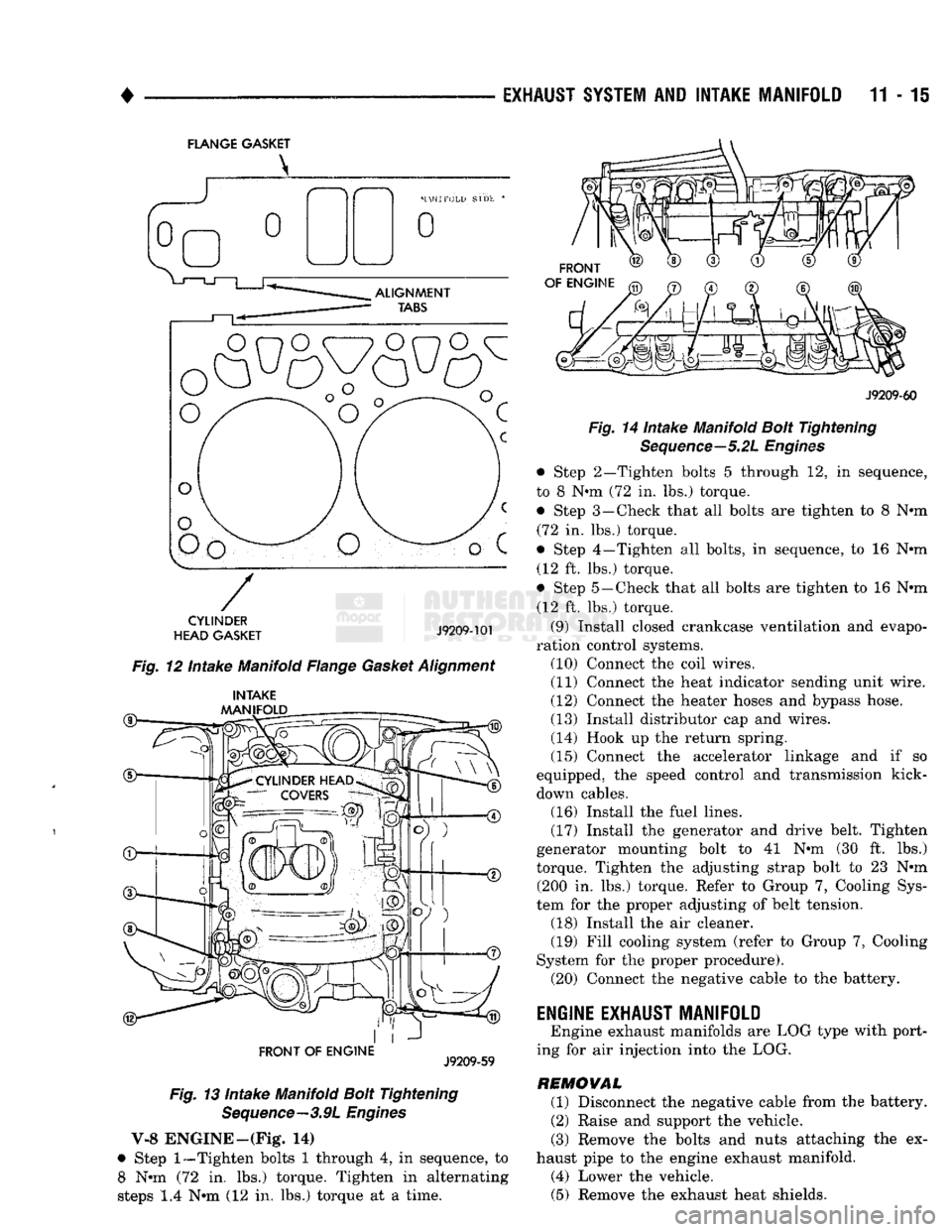
FLANGE GASKET
o
o
CYLINDER
HEAD GASKET
J9209-101
Fig. 12 Intake Manifold Flange Gasket Alignment
®— INTAKE
MANIFOLD
FRONT OF
ENGINE
J9209-59
Fig. 13 Intake Manifold Bolt Tightening Sequence—3.9L Engines
V-8 ENGINE—(Fig* 14)
• Step
1—Tighten
bolts 1 through 4, in sequence, to 8 Nun (72 in. lbs.) torque. Tighten in alternating
steps 1.4 Nun (12 in. lbs.) torque at a time.
FRONT
OF ENGINE
J9209-60
Fig. 14 Intake Manifold Bolt Tightening Sequence—5.2L Engines
• Step 2—Tighten bolts 5 through 12, in sequence,
to 8 Nun (72 in. lbs.) torque. • Step 3—Check that all bolts are tighten to 8 Nun (72 in. lbs.) torque.
• Step 4—Tighten all bolts, in sequence, to 16 Nun (12 ft. lbs.) torque.
• Step 5—Check that all bolts are tighten to 16 Nun (12 ft. lbs.) torque.
(9) Install closed crankcase ventilation and evapo
ration control systems. (10) Connect the coil wires.
(11) Connect the heat indicator sending unit wire.
(12) Connect the heater hoses and bypass hose.
(13) Install distributor cap and wires.
(14) Hook up the return spring.
(15) Connect the accelerator linkage and if so
equipped, the speed control and transmission kick-
down cables. (16) Install the fuel lines,
(17) Install the generator and drive belt. Tighten
generator mounting bolt to 41 Nun (30 ft. lbs.)
torque. Tighten the adjusting strap bolt to 23 Nun (200 in. lbs.) torque. Refer to Group 7, Cooling Sys
tem for the proper adjusting of belt tension. (18) Install the air cleaner. (19) Fill cooling system (refer to Group 7, Cooling
System for the proper procedure). (20) Connect the negative cable to the battery.
ENGINE EXHAUST MANIFOLD
Engine exhaust manifolds are LOG type with port
ing for air injection into the LOG.
REMOVAL (1) Disconnect the negative cable from the battery.
(2) Raise and support the vehicle.
(3) Remove the bolts and nuts attaching the ex
haust pipe to the engine exhaust manifold. (4) Lower the vehicle. (5) Remove the exhaust heat shields.
Page 781 of 1502
11
- 22
EXHAUST
SYSTEM
AND
INTAKE MANIFOLD
•
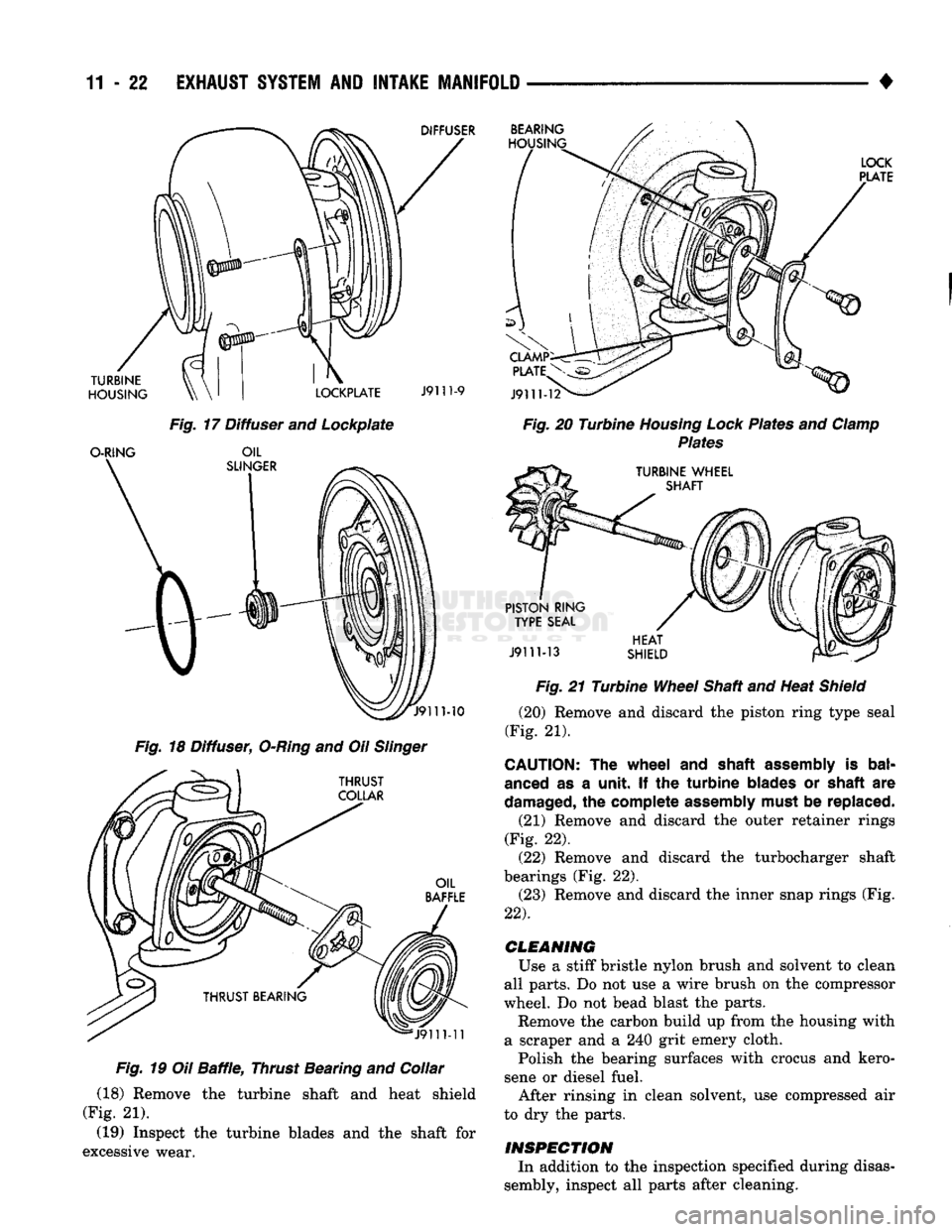
DIFFUSER
TURBINE
HOUSING
O-RING BEARING
HOUSING
LOCKPLATE
J9111-9
Fig.
17 Diffuser and Lockplate
OIL
SLINGER
MO
Fig.
18 Diffuser,
O-Ring
and Oil
Slinger
THRUST
COLLAR
OIL
BAFFLE
J9111-11
Fig.
19 Oil
Baffle,
Thrust Bearing and Collar
(18) Remove the turbine shaft and heat shield
(Fig. 21).
(19) Inspect the turbine blades and the shaft for
excessive wear.
LOCK
PLATE
J9111-12
Fig.
20 Turbine
Housing Lock
Plates and
Clamp
Plates
TURBINE WHEEL SHAFT
PISTON RING TYPE SEAL
J9111-13
HEAT
SHIELD Fig.
21 Turbine
Wheel
Shaft and Heat
Shield
(20) Remove and discard the piston ring type seal
(Fig. 21).
CAUTION:
The
wheel
and
shaft assembly
is
bal
anced
as a
unit.
If the
turbine blades
or
shaft
are
damaged,
the
complete assembly must
be
replaced.
(21) Remove and discard the outer retainer rings
(Fig. 22). (22) Remove and discard the turbocharger shaft
bearings (Fig. 22). (23) Remove and discard the inner snap rings (Fig.
22).
CLEANING
Use a stiff bristle nylon brush and solvent to clean
all parts. Do not use a wire brush on the compressor
wheel. Do not bead blast the parts. Remove the carbon build up from the housing with
a scraper and a 240 grit emery cloth.
Polish the bearing surfaces with crocus and kero
sene or diesel fuel. After rinsing in clean solvent, use compressed air
to dry the parts.
INSPECTION
In addition to the inspection specified during disas
sembly, inspect all parts after cleaning.
Page 783 of 1502
11
- 24
EXHAUST
SYSTEM
AND
INTAKE
MANIFOLD
(10) Install the oil baffle. Check the balance mark
alignment. (11) Install the piston ring type seal on the oil
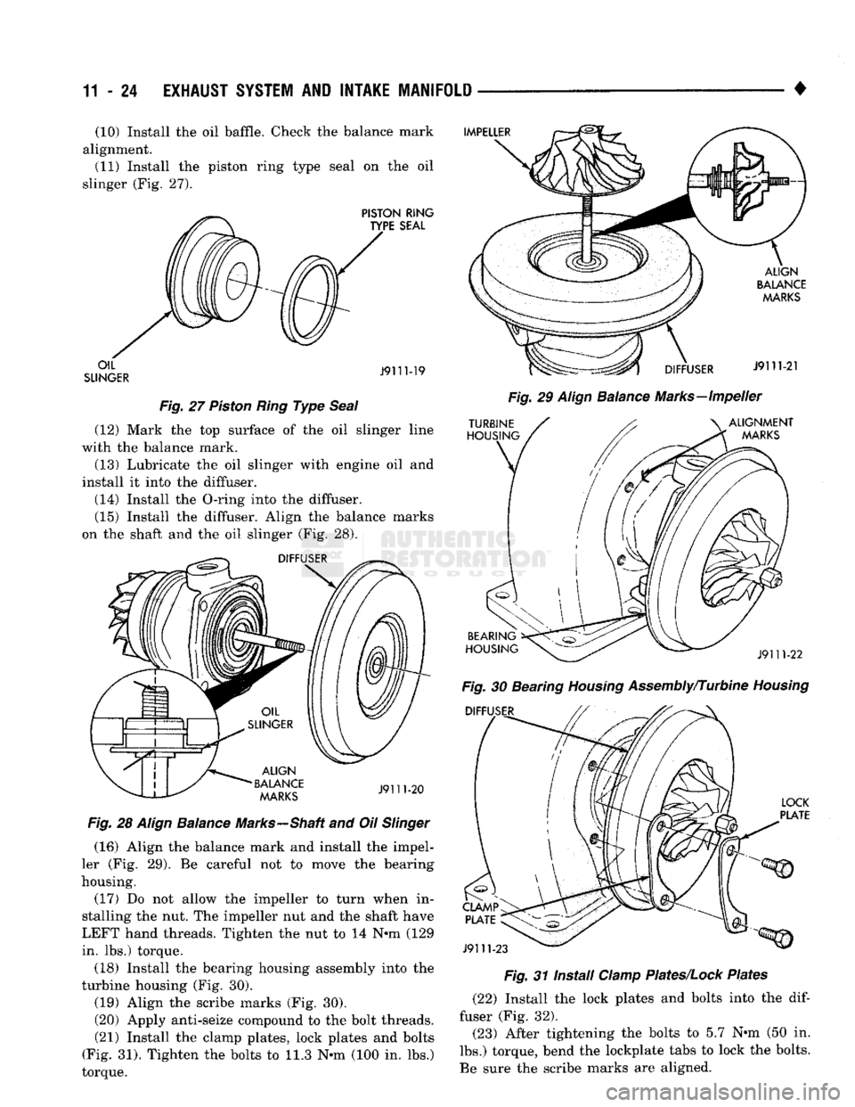
slinger (Fig. 27).
Fig.
27
Piston
Ring
Type
Seal
(12) Mark the top surface of the oil slinger line
with the balance mark.
(13) Lubricate the oil slinger with engine oil and
install it into the diffuser.
(14) Install the O-ring into the diffuser. (15) Install the diffuser. Align the balance marks
on the shaft and the oil slinger (Fig. 28).
Fig.
28
Align
Balance
Marks—Shaft and Oil
Slinger
(16) Align the balance mark and install the impel
ler (Fig. 29). Be careful not to move the bearing
housing. (17) Do not allow the impeller to turn when in
stalling the nut. The impeller nut and the shaft have
LEFT hand threads. Tighten the nut to 14 N-m (129
in. lbs.) torque.
(18) Install the bearing housing assembly into the
turbine housing (Fig. 30). (19) Align the scribe marks (Fig. 30).
(20) Apply anti-seize compound to the bolt threads. (21) Install the clamp plates, lock plates and bolts
(Fig. 31). Tighten the bolts to 11.3 N-m (100 in. lbs.)
torque.
Fig.
29
Align
Balance
Marks—Impeller
Fig.
30 Bearing
Housing
Assembly/Turbine
Housing
Fig.
31 Install
Clamp
Plates/Lock
Plates
(22) Install the lock plates and bolts into the
dif
fuser (Fig. 32).
(23) After tightening the bolts to 5.7 N-m (50 in.
lbs.) torque, bend the lockplate tabs to lock the bolts.
Be sure the scribe marks are aligned.
Page 832 of 1502
•
FUEL
SYSTEM
14 - 13 (1) Disconnect negative cable from the battery.
(2) Perform the Fuel Pressure Release Procedure.
Refer to the Fuel Pressure Release Procedure in this section.
(3) Bend the retainer tab downward.
CAUTION:
If the
retainer
tab on the
removable
pull
tab
is not
bent
down
prior
to
disconnecting
the
quick-connect
fitting,
the
connector
could
be
dam
aged.
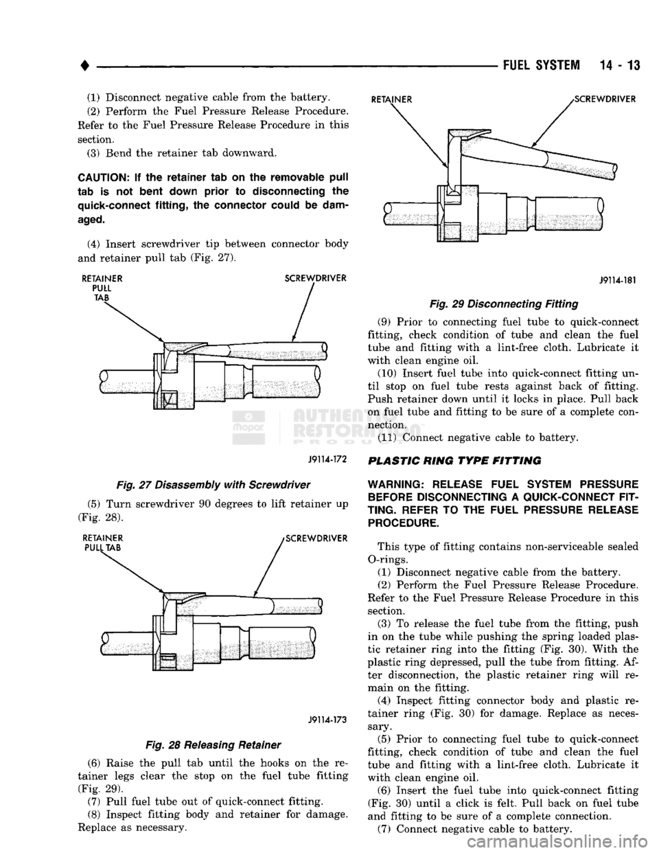
(4) Insert screwdriver tip between connector body
and retainer pull tab (Fig. 27).
RETAINER
SCREWDRIVER
J9114-172
J9114-181
Fig.
29
Disconnecting
Fitting
(9) Prior to connecting fuel tube to quick-connect
fitting, check condition of tube and clean the fuel
tube and fitting with a lint-free cloth. Lubricate it
with clean engine oil.
(10) Insert fuel tube into quick-connect fitting un
til stop on fuel tube rests against back of fitting.
Push retainer down until it locks in place. Pull back on fuel tube and fitting to be sure of a complete con
nection.
(11) Connect negative cable to battery.
PLASTIC RING TYPE FITTING
Fig.
27
Disassembly
with
Screwdriver
(5) Turn screwdriver 90 degrees to lift retainer up
(Fig. 28).
RETAINER
PULL
TAB
SCREWDRIVER
J9114-173
Fig.
28
Releasing
Retainer
(6) Raise the pull tab until the hooks on the re
tainer legs clear the stop on the fuel tube fitting
(Fig. 29). (7) Pull fuel tube out of quick-connect fitting.
(8) Inspect fitting body and retainer for damage.
Replace as necessary.
WARNING:
RELEASE
FUEL
SYSTEM PRESSURE
BEFORE
DISCONNECTING
A
QUICK-CONNECT FIT
TING.
REFER
TO THE
FUEL
PRESSURE RELEASE PROCEDURE.
This type of fitting contains non-serviceable sealed
O-rings. (1) Disconnect negative cable from the battery.
(2) Perform the Fuel Pressure Release Procedure.
Refer to the Fuel Pressure Release Procedure in this section. (3) To release the fuel tube from the fitting, push
in on the tube while pushing the spring loaded plas
tic retainer ring into the fitting (Fig. 30). With the
plastic ring depressed, pull the tube from fitting. Af ter disconnection, the plastic retainer ring will re
main on the fitting.
(4) Inspect fitting connector body and plastic re
tainer ring (Fig. 30) for damage. Replace as neces sary.
(5) Prior to connecting fuel tube to quick-connect
fitting, check condition of tube and clean the fuel
tube and fitting with a lint-free cloth. Lubricate it
with clean engine oil.
(6) Insert the fuel tube into quick-connect fitting
(Fig. 30) until a click is felt. Pull back on fuel tube
and fitting to be sure of a complete connection.
(7) Connect negative cable to battery.