Page 233 of 676

INSP
ADJ
3. Einstellen:
Antriebsketten-Durchhang
Antriebsketten-Durchhang ein-
stellen:
Die Achsmutter 1 und Siche-
rungsmuttern 2 lokkern.
Den Antriebsketten-Durchhang
durch Verdrehen der Einstell-
schraube 3 einstellen.
Kette straffen → Einstell-
schraube 3 entgegen dem
Uhrzeigersinn drehen.
Kette lockern → Einstell-
schraube 3 im Uhrzeigersinn
drehen und das Rad nach
vorn drücken.
Beide Seiten um dieselbe Anzahl
Umdrehungen verstellen, um die
Radausrichtung nicht zu verstel-
len. (Beide Kettenspanner sind
mit Ausrichtungsmarkierungen
a versehen.)
HINWEIS:
Bei der Einstellung sicherstellen,
dass die Antriebskette, von hinten
betrachtet, mit dem Kettenrad
fluchtet.
ACHTUNG:
Eine falsch gespannte Antriebs-
kette verursacht erhöhten Ver-
schleiß von Kette, Motor,
Lagern und anderen wichtigen
Teilen. Daher darauf achten,
dass der Kettendurchhang sich
im Sollbereich befindet.
Beim Festziehen der Achsmutter
die Antriebskette niederdrücken.
T R..
Achsmutter:
125 Nm
(12,5 m kg, 90 ft lb)
Die Sicherungsmuttern festziehen.
T R..
Sicherungsmutter:
19 Nm
(1,9 m kg, 12 ft lb)
TELESKOPGABEL
KONTROLLIEREN
1. Kontrollieren:
Funktion der Teleskopgabel
Die Teleskopgabel bei gezo-
genem Handbremshebel
mehrmals ein- und ausfedern.
Stockend/undicht → Instand
setzen, ggf. erneuern. 3. Régler:
Tension de la chaîne de transmis-
sion
Etapes du réglage de la tension de
la chaîne de transmission:
Desserrer l’écrou de l’axe 1 et les
contre-écrous 2.
Régler la tension de la chaîne en
tournant les dispositifs de réglage 3.
Pour tendre → Tourner le dispositif
de réglage 3 dans le sens inverse
des aiguilles d’une montre.
Pour détendre → Tourner le dispo-
sitif de réglage 3 dans le sens
des aiguilles d’une montre et
pousser la roue vers l’avant.
Tourner chaque dispositif de
réglage du même nombre de tours
pour maintenir l’alignement cor-
rect de l’axe. (Des repères a sont
prévus de chaque côté du tendeur
de chaîne.)
N.B.:
Tourner le dispositif de réglage de
manière que la chaîne soit alignée
avec le pignon, vue de l’arrière.
ATTENTION:
Une chaîne trop tendue impose un
effort excessif au moteur et à
d’autres organes vitaux. Maintenir
la tension dans les limites spécifiées.
Serrer l’écrou d’axe tout en
appuyant sur la chaîne de transmis-
sion afin de la tendre.
T R..
Ecrou d’axe:
125 Nm
(12,5 m kg, 90 ft lb)
Serrer les contre-écrous.
T R..
Contre-écrou:
19 Nm
(1,9 m kg, 12 ft lb)
CONTROLE DE LA FOURCHE
1. Contrôler:
Fonctionnement régulier de la
fourche avant
Actionner le frein avant et enfon-
cer la fourche.
Fonctionnement irrégulier/fuite
d’huile → Réparer ou remplacer.3. Regolare:
Gioco della catena di trasmis-
sione
Operazioni per la regolazione del
gioco della catena di trasmissione:
Allentare il dado asse della ruota
1 e i controdadi 2.
Regolare il gioco della catena di
trasmissione ruotando i dispositivi
di regolazione 3.
Per serrare → Ruotare il disposi-
tivo di regolazione 3 in senso
antiorario.
Per allentare → Ruotare il disposi-
tivo di regolazione 3 in senso ora-
rio e spingere la ruota in avanti.
Ruotare in modo esattamente iden-
tico ogni dispositivo di regolazione
per mantenere il corretto allinea-
mento dell’asse. (Sono presenti
contrassegni a su ogni lato
dell’allineamento dell’estrattore
della catena di trasmissione).
NOTA:
Ruotare il dispositivo di regolazione
in modo che la catena di trasmissione
sia in linea con la corona, come
mostrato nella vista posteriore.
ATTENZIONE:
Se il gioco della catena di trasmis-
sione è troppo ridotto, il motore e
gli altri componenti vitali si sovrac-
caricano; mantenere il gioco entro i
limiti indicati.
Serrare il dado asse della ruota e
contemporaneamente spingere verso
il basso la catena di trasmissione.
T R..
Dado asse della ruota:
125 Nm
(12,5 m kg, 90 ft lb)
Serrare i controdadi.
T R..
Controdado:
19 Nm
(1,9 m kg, 12 ft lb)
CONTROLLO FORCELLA
ANTERIORE
1. Controllare:
Funzionamento uniforme della
forcella anteriore
Azionare il freno anteriore e dare
un colpo alla forcella anteriore.
Funzionamento non uniforme/
perdita di olio → Riparare o sosti-
tuire.
CONTROLE DE LA FOURCHE
TELESKOPGABEL KONTROLLIEREN
CONTROLLO FORCELLA ANTERIORE
3 - 32
Page 234 of 676

3 - 33
INSP
ADJFRONT FORK OIL SEAL AND DUST SEAL CLEANING/
FRONT FORK INTERNAL PRESSURE RELIEVING/
FRONT FORK REBOUND DAMPING FORCE ADJUSTMENT
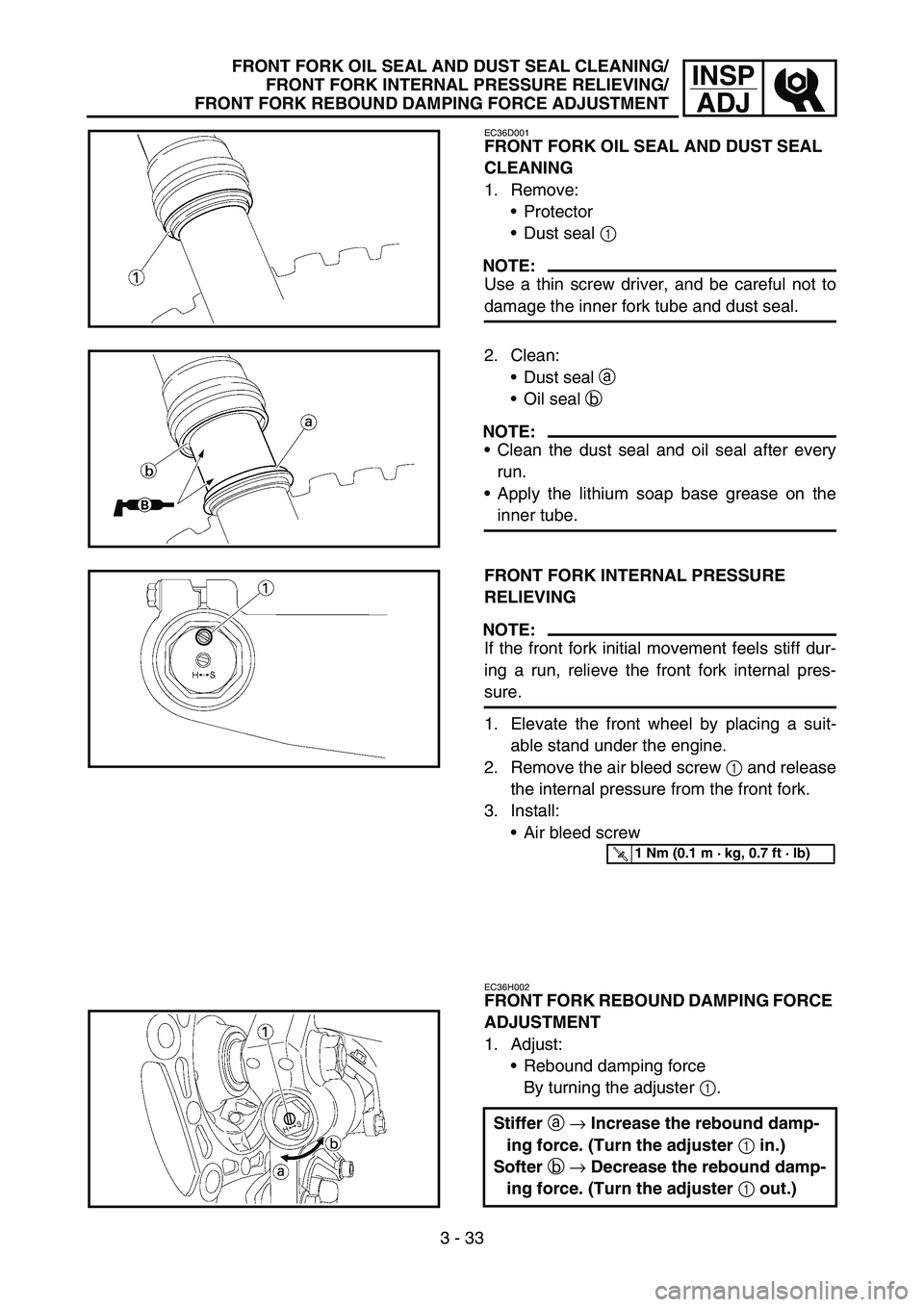
EC36D001
FRONT FORK OIL SEAL AND DUST SEAL
CLEANING
1. Remove:
Protector
Dust seal 1
NOTE:
Use a thin screw driver, and be careful not to
damage the inner fork tube and dust seal.
2. Clean:
Dust seal a
Oil seal b
NOTE:
Clean the dust seal and oil seal after every
run.
Apply the lithium soap base grease on the
inner tube.
FRONT FORK INTERNAL PRESSURE
RELIEVING
NOTE:
If the front fork initial movement feels stiff dur-
ing a run, relieve the front fork internal pres-
sure.
1. Elevate the front wheel by placing a suit-
able stand under the engine.
2. Remove the air bleed screw 1 and release
the internal pressure from the front fork.
3. Install:
Air bleed screw
EC36H002
FRONT FORK REBOUND DAMPING FORCE
ADJUSTMENT
1. Adjust:
Rebound damping force
By turning the adjuster 1.
Stiffer a → Increase the rebound damp-
ing force. (Turn the adjuster 1 in.)
Softer b → Decrease the rebound damp-
ing force. (Turn the adjuster 1 out.)
T R..1 Nm (0.1 m · kg, 0.7 ft · lb)
Page 235 of 676

INSP
ADJ
GABEL-DICHT- UND
-STAUBSCHUTZRINGE REINIGEN
1. Demontieren:
Protektor
Staubschutzring 1
HINWEIS:
Einen schmalen Schlitz-Schrauben-
dreher verwenden und darauf ach-
ten, dass das Gleitrohr und der
Staubschutzring nicht beschädigt
werden.
2. Reinigen:
Staubschutzring a
Dichtring b
HINWEIS:
Die Staubschutz- und Dichtringe
nach jeder Fahrt reinigen.
Das Gleitrohr mit Lithiumseifenfett
bestreichen.
GABEL-LUFTDRUCK
AUSGLEICHEN
HINWEIS:
Wenn die Gabel am Anfang des
Federwegs steif ist, muss der Gabel-
Luftdruck ausgeglichen werden.
1. Das Motorrad aufbocken, um
das Vorderrad vom Boden abzu-
heben.
2. Die Entlüftungsschraube 1 her-
ausdrehen, um den Gabel-Luft-
druck auszugleichen.
3. Montieren:
Entlüftungsschraube
ZUGSTUFEN-DÄMPFUNGSKRAFT
DER TELESKOPGABEL
EINSTELLEN
1. Einstellen:
Zugstufen-Dämpfungskraft
(durch Verdrehen der Einstell-
schraube 1)
T R..1 Nm (0,1 m · kg, 0,7 ft · lb)
Härter a → Zugstufen-Dämp-
fungskraft erhöhen. (Einstell-
schraube 1 hineindrehen.)
Weicher b → Zugstufen-Dämp-
fungskraft reduzieren. (Ein-
stellschraube 1
herausdrehen.)
NETTOYAGE DE LA BAGUE
D’ETANCHEITE ET DU JOINT
ANTIPOUSSIERE DE FOURCHE
1. Déposer:
Protection
Joint antipoussière 1
N.B.:
Utiliser un petit tournevis et veiller à ne
pas endommager le tube plongeur de la
fourche et le joint antipoussière.
2. Nettoyer:
Joint antipoussière a
Bague d’étanchéité b
N.B.:
Nettoyer le joint antipoussière et la
bague d’étanchéité après chaque
course.
Appliquer de la graisse à savon de
lithium sur le tube plongeur.
REDUCTION DE LA PRESSION
INTERNE DE LA FOURCHE
N.B.:
Si le mouvement initial de la fourche
paraît dur, réduire la pression interne de
la fourche.
1. Surélever la roue avant en plaçant
un support adéquat sous le moteur.
2. Déposer la vis de purge d’air 1 et
évacuer la pression interne de la
fourche.
3. Monter:
Vis de purge d’air
REGLAGE DE LA FORCE
D’AMORTISSEMENT A LA
DETENTE DE LA FOURCHE
1. Régler:
Force d’amortissement à la détente
En tournant le dispositif de
réglage 1.
T R..1 Nm (0,1 m · kg, 0,7 ft · lb)
Plus dur a → Augmenter la force
d’amortissement à la détente.
(Visser le dispositif de réglage
1.)
Plus mou b → Diminuer la force
d’amortissement à la détente.
(Dévisser le dispositif de réglage
1.)
PULIZIA PARAOLIO E
GUARNIZIONE PARAPOLVERE
FORCELLA ANTERIORE
1. Togliere:
Protezione
Guarnizione parapolvere 1
NOTA:
Utilizzare un cacciavite di piccole
dimensioni e prestare attenzione a non
danneggiare il tubo interno della forcella
e la guarnizione parapolvere.
2. Pulire:
Guarnizione parapolvere a
Paraolio b
NOTA:
Pulire la guarnizione parapolvere e il
paraolio dopo ogni utilizzo del mezzo.
Applicare il grasso a base di sapone di
litio sul tubo interno.
ALLEGGERIMENTO DELLA
PRESSIONE INTERNA DELLA
FORCELLA ANTERIORE
NOTA:
Se durante l’utilizzo del mezzo il movi-
mento iniziale della forcella anteriore
appare rigido, alleggerire la pressione
interna della forcella anteriore.
1. Sollevare la ruota anteriore ponendo
un idoneo cavalletto sotto il motore.
2. Togliere la vite di spurgo aria 1 e
rilasciare la pressione interna dalla
forcella anteriore.
3. Installare:
Vite di spurgo aria
REGOLAZIONE DELLA FORZA DI
SMORZAMENTO IN ESTENSIONE
DELLA FORCELLA ANTERIORE
1. Regolare:
Forza di smorzamento in estensione
Ruotando il dispositivo di regola-
zione 1.
T R..1 Nm (0,1 m · kg, 0,7 ft · lb)
Rigido a → Aumentare la forza di
smorzamento in estensione.
(Avvitare il dispositivo di regola-
zione 1.)
Morbido b → Diminuire la forza
di smorzamento in estensione.
(Svitare il dispositivo di
regolazione1.)
NETTOYAGE DE LA BAGUE D’ETANCHEITE ET DU JOINT ANTIPOUSSIERE DE FOURCHE/
REDUCTION DE LA PRESSION INTERNE DE LA FOURCHE/
REGLAGE DE LA FORCE D’AMORTISSEMENT A LA DETENTE DE LA FOURCHE
GABEL-DICHT- UND -STAUBSCHUTZRINGE REINIGEN/GABEL-LUFTDRUCK AUSGLEICHEN/
ZUGSTUFEN-DÄMPFUNGSKRAFT DER TELESKOPGABEL EINSTELLEN
PULIZIA PARAOLIO E GUARNIZIONE PARAPOLVERE FORCELLA ANTERIORE/
ALLEGGERIMENTO DELLA PRESSIONE INTERNA DELLA FORCELLA ANTERIORE/
REGOLAZIONE DELLA FORZA DI SMORZAMENTO IN ESTENSIONE DELLA FORCELLA ANTERIORE
3 - 33
Page 236 of 676
3 - 34
INSP
ADJFRONT FORK COMPRESSION DAMPING FORCE
ADJUSTMENT
STANDARD POSITION:
This is the position which is back by the spe-
cific number of clicks from the fully turned-in
position.
* For EUROPE
CAUTION:
Do not force the adjuster past the minimum
or maximum extent of adjustment. The
adjuster may be damaged.
WARNING
Always adjust each front fork to the same
setting. Uneven adjustment can cause poor
handling and loss of stability.
Extent of adjustment
Maximum Minimum
Fully turned in
position20 clicks out (from
maximum position)
Standard position:
6 clicks out
* 11 clicks out
FRONT FORK COMPRESSION DAMPING
FORCE ADJUSTMENT
1. Adjust:
Compression damping force
By turning the adjuster 1.
Stiffer
a
→ Increase the compression
damping force. (Turn the adjuster
1
in.)
Softer
b
→ Decrease the compression
damping force. (Turn the adjuster
1
out.)
Page 237 of 676

INSP
ADJ
STANDARD-EINSTELLUNG:
Die Einstellschraube völlig hinein-
drehen und dann um die vorge-
schriebene Anzahl Raststellungen
herausdrehen.
* EUROPE
ACHTUNG:
Den Einstellmechanismus nie
über die Minimal- oder Maxi-
maleinstellung hinausdrehen, um
diesen nicht zu beschädigen.
WARNUNG
Sicherstellen, dass beide Gabel-
beine gleichmäßig eingestellt
sind. Eine ungleichmäßige Ein-
stellung beeinträchtigt das Fahr-
verhalten.
Einstellbereich
Maximal Minimal
Vollständig
hineingedreht20. Raststel-
lung (aus der
Maximalstel-
lung)
Normaleinstellung:
6. Raststellung
* 11. Raststellung
DRUCKSTUFEN-
DÄMPFUNGSKRAFT DER
TELESKOPGABEL EINSTELLEN
1. Einstellen:
Druckstufen-Dämpfungskraft
(durch Verdrehen der Einstell-
schraube 1)
Härter a → Druckstufen-Dämp-
fungskraft erhöhen. (Einstell-
schraube 1 hineindrehen.)
Weicher b → Druckstufen-
Dämpfungskraft reduzieren.
(Einstellschraube 1 heraus-
drehen.)
POSITION STANDARD:
Position à laquelle le dispositif de
réglage est dévissé du nombre de
déclics spécifié par rapport à la posi-
tion complètement vissée.
* EUROPE
ATTENTION:
Ne pas forcer le dispositif de réglage
au-delà des positions minimum ou
maximum. Cela pourrait l’endomma-
ger.
AVERTISSEMENT
Toujours régler de la même manière
chaque bras de la fourche. Un réglage
inégal risque de diminuer la maniabi-
lité et la stabilité.
Plage de réglage
Maximum Minimum
Position complè-
tement visséeDesserrer de 20
déclics (par rap-
port à la position
maximum)
Position standard:
dévissé de 6 déclics
* dévissé de 11 déclics
REGLAGE DE LA FORCE
D’AMORTISSEMENT A LA
COMPRESSION DE LA FOURCHE
1. Régler:
Force d’amortissement à la com-
pression
En tournant le dispositif de
réglage 1.
Plus dur a → Augmenter la force
d’amortissement à la compres-
sion. (Visser le dispositif de
réglage 1.)
Plus mou b → Diminuer la force
d’amortissement à la compres-
sion. (Dévisser le dispositif de
réglage 1.)
POSIZIONE STANDARD:
Posizione ritratta rispetto alla posi-
zione di avvitamento completo del
numero indicato di scatti verso
l’esterno.
* EUROPE
ATTENZIONE:
Non forzare il dispositivo di regola-
zione oltre il valore minimo o massimo
del punto di regolazione. Il dispositivo
potrebbe danneggiarsi.
AVVERTENZA
Regolare sempre allo stesso modo ogni
forcella anteriore. Una regolazione
disuguale può determinare difficoltà
di manovrabilità e perdita di stabilità.
Entità della regolazione
Massimo Minimo
Avvitamento
completo20 scatti verso
l’esterno (a par-
tire dalla posi-
zione di
avvitamento
massimo)
Posizione standard:
6 scatti verso l’esterno
* 11 scatti verso l’esterno
REGOLAZIONE DELLA FORZA DI
SMORZAMENTO IN COMPRES-
SIONE DELLA FORCELLA ANTE-
RIORE
1. Regolare:
Forza di smorzamento in com-
pressione
Ruotando il dispositivo di regola-
zione 1.
Rigido a → Aumentare la forza di
smorzamento in compressione.
(Avvitare il dispositivo di regola-
zione 1.)
Morbido b → Diminuire la forza
di smorzamento in compres-
sione. (Svitare il dispositivo di
regolazione 1.)
REGLAGE DE LA FORCE D’AMORTISSEMENT A LA COMPRESSION DE LA FOURCHE
DRUCKSTUFEN-DÄMPFUNGSKRAFT DER TELESKOPGABEL EINSTELLEN
REGOLAZIONE DELLA FORZA DI SMORZAMENTO IN COMPRESSIONE DELLA
FORCELLA ANTERIORE
3 - 34
Page 238 of 676
3 - 35
INSP
ADJ
REAR SHOCK ABSORBER INSPECTION
Extent of adjustment
Maximum Minimum
Fully turned in
position20 clicks out
(from maximum
position)
STANDARD POSITION:
This is the position which is back by the spe-
cific number of clicks from the fully turned-in
position.
* For EUROPE
CAUTION:
Do not force the adjuster past the minimum
or maximum extent of adjustment. The
adjuster may be damaged.
WARNING
Always adjust each front fork to the same
setting. Uneven adjustment can cause poor
handling and loss of stability.
Standard position:
11 clicks out
* 6 clicks out
EC36K000
REAR SHOCK ABSORBER INSPECTION
1. Inspect:
Swingarm smooth action
Abnormal noise/unsmooth action →
Grease the pivoting points or repair the
pivoting points.
Damage/oil leakage → Replace.
Page 239 of 676

INSP
ADJ
Einstellbereich
Maximal Minimal
Vollständig
hineingedreht20. Raststel-
lung (aus der
Maximalstel-
lung)
STANDARD-EINSTELLUNG:
Die Einstellschraube völlig hinein-
drehen und dann um die vorge-
schriebene Anzahl Raststellungen
herausdrehen.
* EUROPE
ACHTUNG:
Den Einstellmechanismus nie
über die Minimal- oder Maxi-
maleinstellung hinausdrehen, um
diesen nicht zu beschädigen.
WARNUNG
Sicherstellen, dass beide Gabel-
beine gleichmäßig eingestellt
sind. Eine ungleichmäßige Ein-
stellung beeinträchtigt das Fahr-
verhalten.
Standard-einstellung:
11. Raststellung
* 6. Raststellung
FEDERBEIN KONTROLLIEREN
1. Kontrollieren:
Leichtgängigkeit der Schwinge
Geräuschvoll/stockend →
Drehpunkte schmieren/ in
Stand setzen.
Beschädigt/undicht → Erneu-
ern.
Plage de réglage
Maximum Minimum
Position complè-
tement visséedévissé de 20
déclics (par rap-
port à la position
maximum)
POSITION STANDARD:
Position à laquelle le dispositif de
réglage est dévissé du nombre de
déclics spécifié par rapport à la posi-
tion complètement vissée.
* EUROPE
ATTENTION:
Ne pas forcer le dispositif de réglage
au-delà des positions minimum ou
maximum. Cela pourrait l’endomma-
ger.
AVERTISSEMENT
Toujours régler de la même manière
chaque bras de la fourche. Un réglage
inégal risque de diminuer la maniabi-
lité et la stabilité.
Position standard:
dévissé de 11 déclics
* dévissé de 6 déclics
CONTROLE DE L’AMORTISSEUR
ARRIERE
1. Contrôler:
Fonctionnement régulier du bras
oscillant
Bruit anormal/fonctionnement
irrégulier → Graisser ou réparer
les points de pivot.
Endommagement/fuite d’huile →
Remplacer.
Entità della regolazione
Massimo Minimo
Avvitamento
completo20 scatti verso
l’esterno (a par-
tire dalla posi-
zione di
avvitamento
massimo)
POSIZIONE STANDARD:
Posizione ritratta rispetto alla posi-
zione di avvitamento completo del
numero indicato di scatti verso
l’esterno.
* EUROPE
ATTENZIONE:
Non forzare il dispositivo di regola-
zione oltre il valore minimo o massimo
del punto di regolazione. Il dispositivo
potrebbe danneggiarsi.
AVVERTENZA
Regolare sempre allo stesso modo ogni
forcella anteriore. Una regolazione
disuguale può determinare difficoltà
di manovrabilità e perdita di stabilità.
Posizione standard:
11 scatti verso l’esterno
* 6 scatti verso l’esterno
CONTROLLO AMMORTIZZA-
TORE POSTERIORE
1. Controllare:
Funzionamento uniforme del for-
cellone oscillante
Rumorosità inusuale/funziona-
mento non uniforme → Lubrifi-
care o riparare i punti di
articolazione.
Danno/perdita di olio → Sostitu-
ire.
CONTROLE DE L’AMORTISSEUR ARRIERE
FEDERBEIN KONTROLLIEREN
CONTROLLO AMMORTIZZATORE POSTERIORE
3 - 35
Page 240 of 676

3 - 36
INSP
ADJREAR SHOCK ABSORBER SPRING PRELOAD
ADJUSTMENT
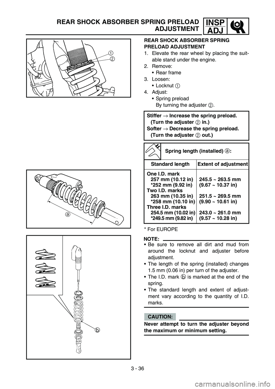
REAR SHOCK ABSORBER SPRING
PRELOAD ADJUSTMENT
1. Elevate the rear wheel by placing the suit-
able stand under the engine.
2. Remove:
Rear frame
3. Loosen:
Locknut 1
4. Adjust:
Spring preload
By turning the adjuster 2.
* For EUROPE
NOTE:
Be sure to remove all dirt and mud from
around the locknut and adjuster before
adjustment.
The length of the spring (installed) changes
1.5 mm (0.06 in) per turn of the adjuster.
The I.D. mark b is marked at the end of the
spring.
The standard length and extent of adjust-
ment vary according to the quantity of I.D.
marks.
CAUTION:
Never attempt to turn the adjuster beyond
the maximum or minimum setting.Stiffer
→ Increase the spring preload.
(Turn the adjuster
2 in.)
Softer
→ Decrease the spring preload.
(Turn the adjuster
2 out.)
Spring length (installed)
a:
Standard length Extent of adjustment
One I.D. mark
257 mm (10.12 in)
*252 mm (9.92 in)
Two I.D. marks
263 mm (10.35 in)
*258 mm (10.10 in)
Three I.D. marks
254.5 mm (10.02 in)
*249.5 mm (9.82 in)245.5 ~ 263.5 mm
(9.67 ~ 10.37 in)
251.5 ~ 269.5 mm
(9.90 ~ 10.61 in)
243.0 ~ 261.0 mm
(9.57 ~ 10.28 in)
b