2006 LAND ROVER FRELANDER 2 torque
[x] Cancel search: torquePage 1277 of 3229
Publi s hed: 11-May-2011
Automatic Transmission/Transaxle -
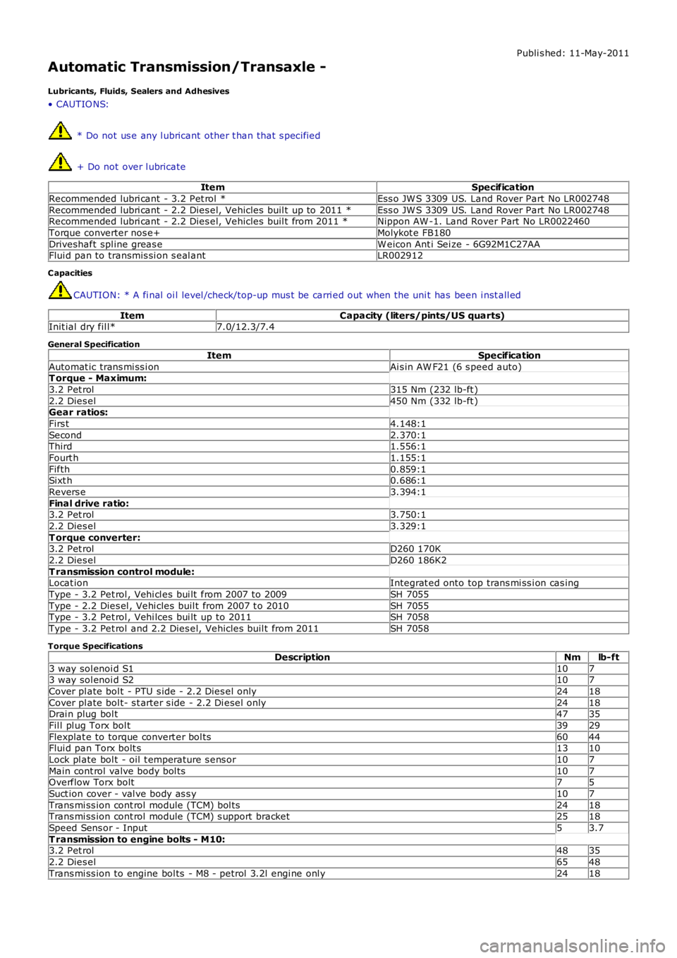
Lubricants, Fluids, Sealers and Adhesives
• CAUTIO NS:
* Do not us e any l ubricant other t han that s pecified
+ Do not over l ubricate
ItemSpecification
Recommended lubri cant - 3.2 Pet rol *Ess o JW S 3309 US. Land Rover Part No LR002748
Recommended lubri cant - 2.2 Dies el, Vehicles buil t up to 2011 *Ess o JW S 3309 US. Land Rover Part No LR002748Recommended lubri cant - 2.2 Dies el, Vehicles buil t from 2011 *Nippon AW -1. Land Rover Part No LR0022460
Torque converter nos e+Molykot e FB180
Driveshaft spl ine greas eW eicon Ant i Sei ze - 6G92M1C27AAFlui d pan to transmis si on s eal antLR002912
C apacities
CAUTION: * A fi nal oi l level /check/top-up mus t be carri ed out when the uni t has been i nst all ed
ItemCapacity (liters/pints/US quarts)Init ial dry fil l*7.0/12.3/7.4
General Specification
ItemSpecification
Automat ic trans mi ss i onAi s in AW F21 (6 s peed auto)T orque - Maximum:
3.2 Pet rol315 Nm (232 lb-ft )
2.2 Dies el450 Nm (332 lb-ft )Gear ratios:
Firs t4.148:1
Second2.370:1Third1.556:1
Fourt h1.155:1
Fifth0.859:1Sixt h0.686:1
Revers e3.394:1
Final drive ratio:3.2 Pet rol3.750:1
2.2 Dies el3.329:1
T orque converter:3.2 Pet rolD260 170K
2.2 Dies elD260 186K2
T ransmission control module:Locat ionIntegrat ed onto top trans mi ss i on cas ing
Type - 3.2 Pet rol , Vehi cl es bui lt from 2007 to 2009SH 7055
Type - 2.2 Dies el , Vehi cles buil t from 2007 t o 2010SH 7055Type - 3.2 Pet rol , Vehi lces bui lt up to 2011SH 7058
Type - 3.2 Pet rol and 2.2 Dies el, Vehicles buil t from 2011SH 7058
Torque Specifications
DescriptionNmlb-ft
3 way sol enoi d S11073 way sol enoi d S2107
Cover pl ate bol t - PTU s ide - 2.2 Dies el onl y2418
Cover pl ate bol t- s t arter s ide - 2.2 Di esel only2418Drai n plug bol t4735
Fil l pl ug Torx bol t3929
Flexplat e to torque convert er bol ts6044Flui d pan Torx bolt s1310
Lock pl ate bol t - oil t emperature s ens or107
Main cont rol valve body bol ts107Overflow Torx bolt75
Suct ion cover - val ve body as s y107
Trans mi ss ion cont rol module (TCM) bol ts2418Trans mi ss ion cont rol module (TCM) s upport bracket2518
Speed Sens or - Input53.7
T ransmission to engine bolts - M10:3.2 Pet rol4835
2.2 Dies el6548
Trans mi ss ion to engine bol ts - M8 - petrol 3.2l engi ne onl y2418
Page 1279 of 3229
puts t he t rans mis s ion i nto el ect roni c manual 'CommandShift™ ' mode.For addit ional informat ion, refer t o: Ext ernal Control s (307-05 Automat ic Trans mi s si on/Trans axl e External Controls ,Des cript ion and Operat ion).
The AW F21 trans mi s si on has the foll owing feat ures :
Des igned to be maint enance freeTorque capacit y of 450 NmTrans mis s ion flui d is fi ll for l ifeThe t orque convert er features a control led s l ip feature wit h elect ronically regulat ed lock-up cont rol on gears 2 t o 6Shift programs controll ed by the TCMTCM has an adapti ve capabil it y to ens ure efficient gear s hift qualit y t hroughout t he s ervice l ife of the t rans mi ss i onDiagnost ics avail abl e from the TCM vi a t he high s peed Control ler Area Network (CAN) bus .
TRANSMISSION
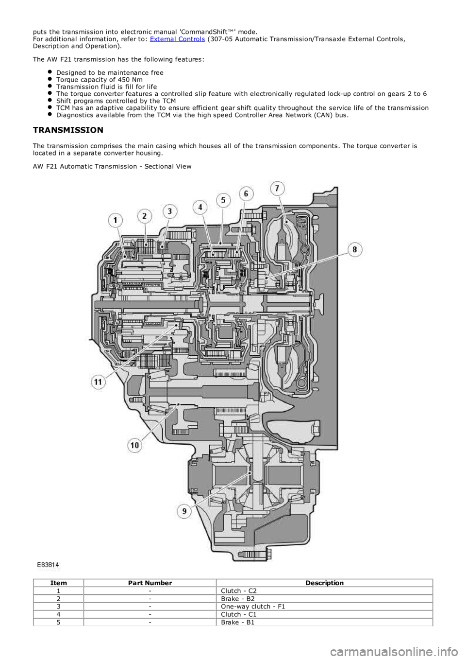
The t ransmis s ion compri ses the mai n casi ng which hous es al l of the t rans mi ss ion components . The torque convert er islocated i n a separat e convert er hous i ng.
AW F21 Aut omat ic Trans mi ss ion - Sect ional Vi ew
ItemPart NumberDescription
1-Clut ch - C2
2-Brake - B23-One-way cl ut ch - F1
4-Clut ch - C1
5-Brake - B1
Page 1280 of 3229
6-Clut ch - C3
7-Torque converter
8-Fluid pump9-Different ial as sembl y
10-Count er dri ven gear
11-Count er dri ve gearThe main cas ing ret ai ns the fl ui d at t he bot t om. A combined drai n/fill er plug i s located i n t he bot t om of t he cas ing. The oillevel is checked by removing t he inner fi ll plug when the t rans mis s ion flui d is at a t emperature of bet ween 50 t o 60°C (122t o 140°F). W hen the oi l fl ow becomes a dri p from the pl ug hol e, the l evel i s correct.
The t ransmis s ion has a flui d cool er whi ch is locat ed on t he Left Hand (LH) end of t he radi ator. The cooler is connect ed t ot he trans mi s si on convert er hous ing by 2 pipes . The fl ui d cooler is connect ed int o t he engi ne cool ing s yst em and cools thet ransmis s ion fluid by heat t rans fer t hrough t he cooler t o t he engi ne cool ant .For addit ional informat ion, refer t o: Trans mis s ion Cooli ng (307-02 Trans mis s ion/Trans axle Cooli ng, Des cri pti on andOperat ion).
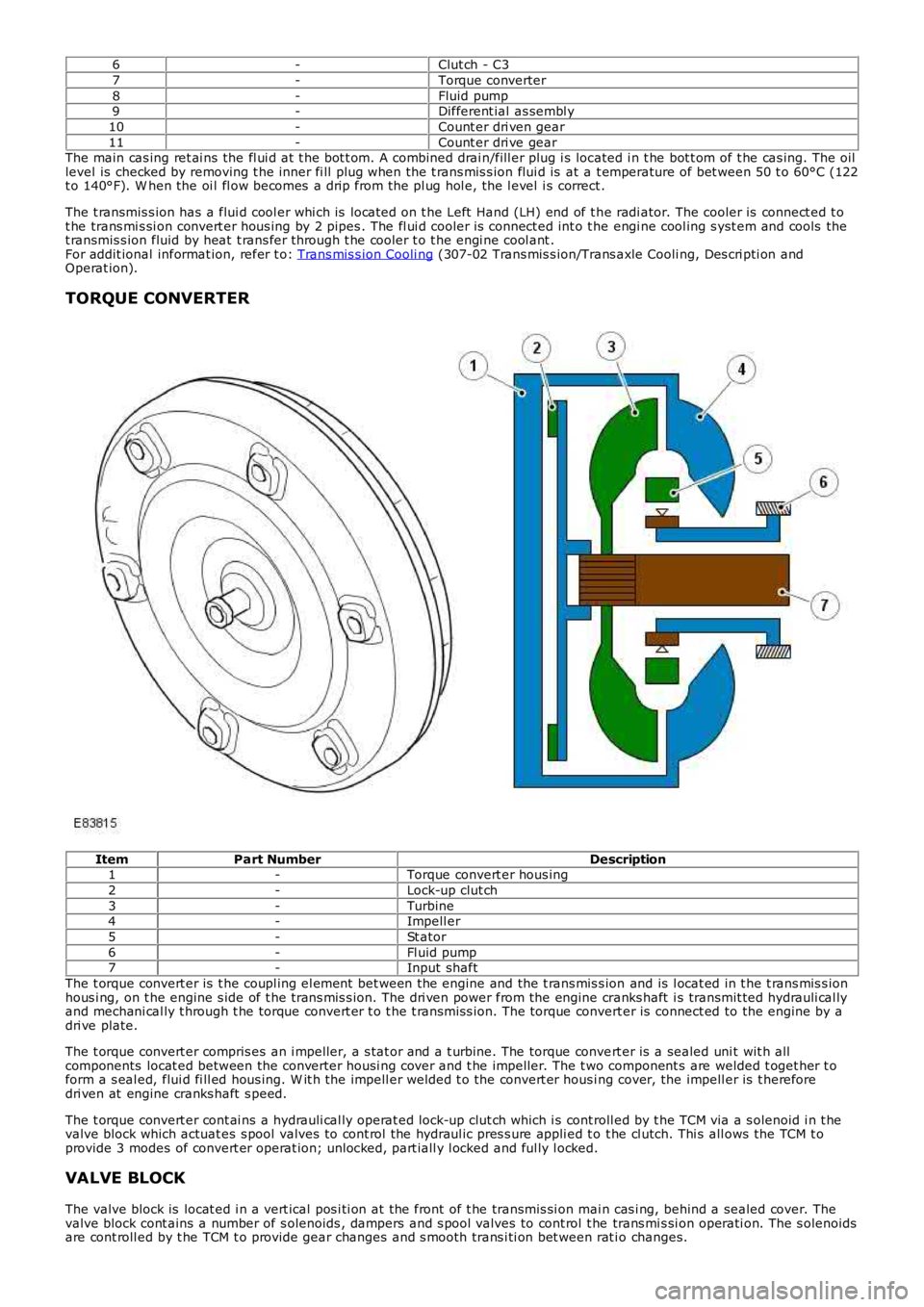
TORQUE CONVERTER
ItemPart NumberDescription1-Torque convert er hous ing
2-Lock-up clut ch
3-Turbine4-Impell er
5-St ator
6-Fl uid pump7-Input shaft
The t orque convert er is t he coupl ing el ement bet ween the engine and the t rans mis s ion and is l ocat ed in t he t rans mis s ionhous i ng, on t he engine s ide of t he t rans mis s ion. The dri ven power from the engine cranks haft i s transmit ted hydrauli cal lyand mechani cal ly t hrough t he torque convert er t o t he t rans mis s ion. The torque convert er is connect ed to the engine by adri ve plate.
The t orque convert er compris es an i mpeller, a s tat or and a t urbine. The torque convert er is a sealed uni t wit h allcomponents locat ed between the converter housi ng cover and t he impel ler. The t wo component s are welded t oget her t oform a s eal ed, flui d fi ll ed hous ing. W it h the impell er welded t o the convert er hous ing cover, the impell er is t hereforedri ven at engine cranks haft s peed.
The t orque convert er cont ai ns a hydrauli cal ly operat ed lock-up clut ch which i s cont roll ed by t he TCM via a s olenoid i n t hevalve block which actuat es s pool valves to cont rol the hydraul ic pres s ure appli ed t o t he cl utch. Thi s all ows the TCM t oprovide 3 modes of convert er operat ion; unlocked, part iall y l ocked and ful ly l ocked.
VALVE BLOCK
The valve block is locat ed i n a vert ical pos i ti on at the front of t he transmis si on mai n cas i ng, behind a sealed cover. Thevalve block cont ains a number of s olenoids , dampers and s pool valves to cont rol t he trans mi s si on operati on. The s olenoidsare cont roll ed by t he TCM t o provide gear changes and s mooth trans i ti on bet ween rat io changes.
Page 1282 of 3229
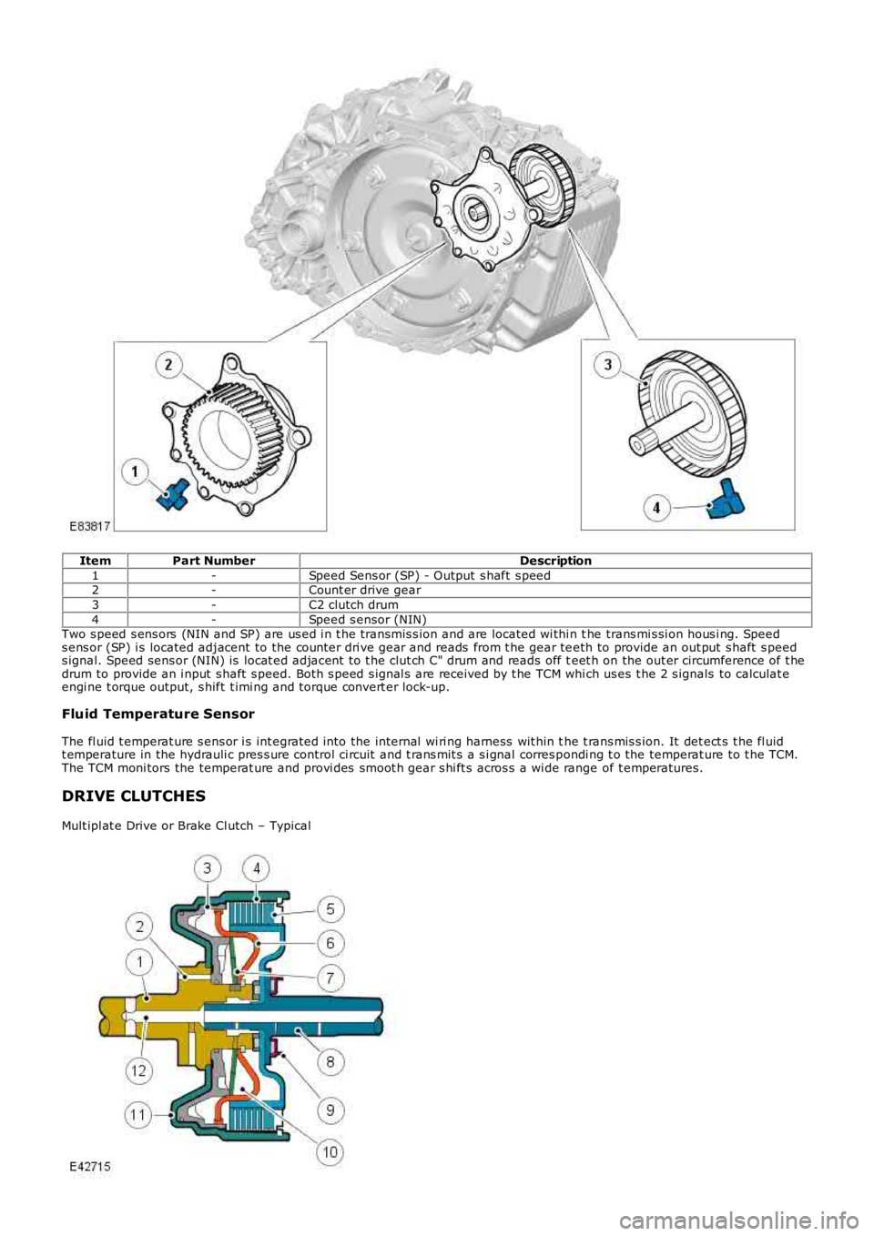
ItemPart NumberDescription
1-Speed Sens or (SP) - Output s haft s peed2-Count er drive gear
3-C2 clutch drum
4-Speed s ensor (NIN)Two s peed s ens ors (NIN and SP) are us ed i n t he transmis s ion and are located wi thi n the trans mi s si on hous i ng. Speeds ens or (SP) i s located adjacent to the counter dri ve gear and reads from t he gear teeth to provide an out put s haft s peeds ignal. Speed sens or (NIN) is locat ed adjacent to t he clut ch C" drum and reads off teet h on the out er circumference of t hedrum to provide an i nput s haft s peed. Bot h s peed s ignal s are received by t he TCM which us es t he 2 s ignals to calculat eengi ne t orque output, s hift t imi ng and torque convert er lock-up.
Fluid Temperature Sensor
The fl uid t emperat ure s ens or i s int egrated into the internal wi ri ng harness wit hin the t rans mis s ion. It det ect s t he fl uidt emperature in the hydrauli c pres s ure control ci rcuit and t rans mit s a s i gnal corres pondi ng t o the temperat ure to t he TCM.The TCM moni tors the temperat ure and provi des smoot h gear s hi ft s acros s a wi de range of t emperatures.
DRIVE CLUTCHES
Mult ipl at e Drive or Brake Cl utch – Typical
Page 1285 of 3229
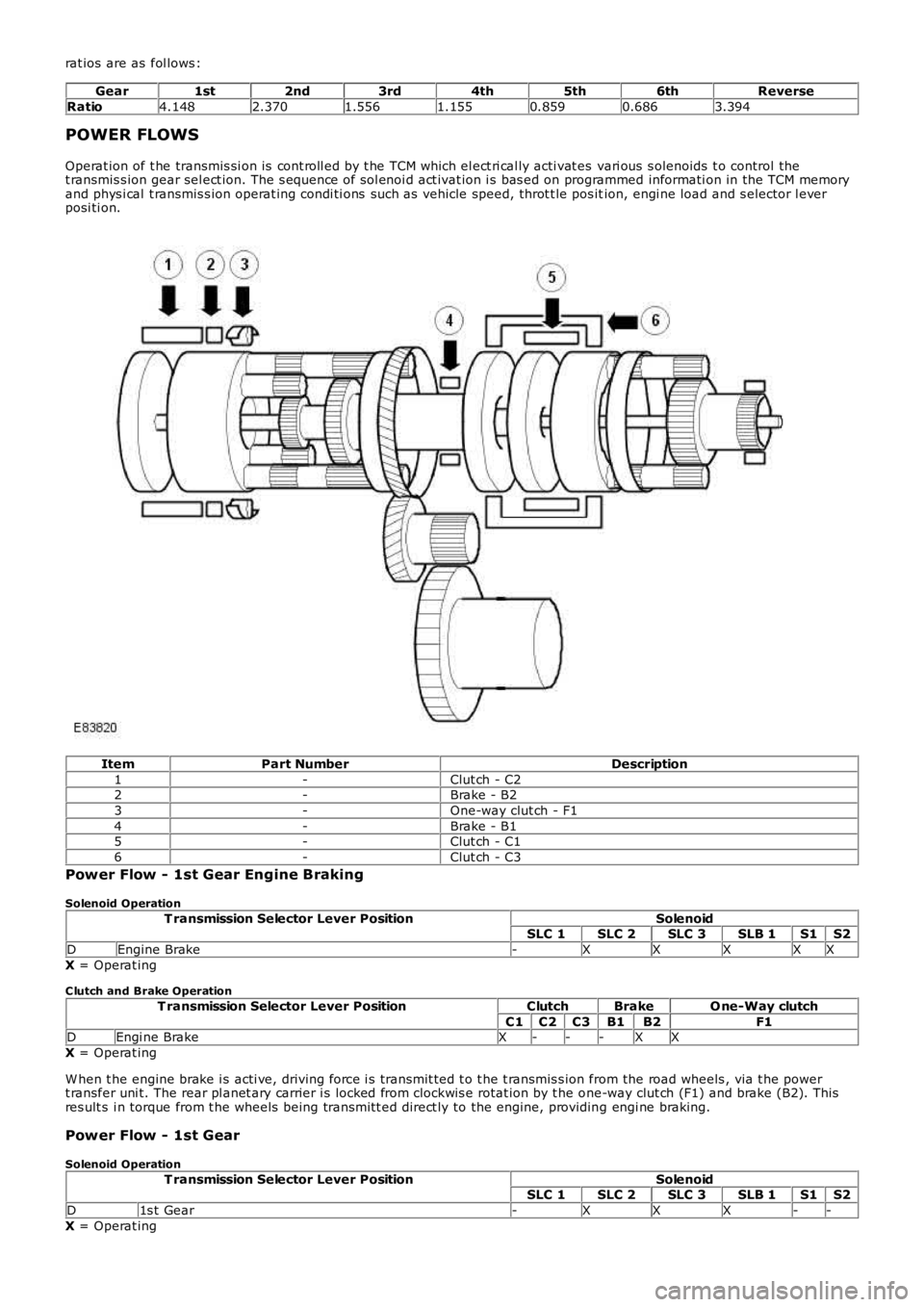
rat ios are as fol lows :
Gear1st2nd3rd4th5th6thReverse
Ratio4.1482.3701.5561.1550.8590.6863.394
POWER FLOWS
Operat ion of t he transmis si on is cont roll ed by t he TCM which el ect ri cal ly acti vat es vari ous s olenoids t o control thet ransmis s ion gear sel ect ion. The s equence of sol enoi d act ivat ion i s bas ed on programmed informati on in the TCM memoryand phys i cal t ransmis s ion operat ing condi ti ons such as vehicle speed, throt t le pos ition, engi ne load and s elector l everposi ti on.
ItemPart NumberDescription
1-Clut ch - C22-Brake - B2
3-One-way clut ch - F1
4-Brake - B15-Clut ch - C1
6-Clut ch - C3
Power Flow - 1st Gear Engine Braking
Solenoid Operation
T ransmission Selector Lever PositionSolenoidSLC 1SLC 2SLC 3SLB 1S1S2
DEngine Brake-XXXXX
X = Operat ing
C lutch and Brake Operation
T ransmission Selector Lever PositionClutchBrakeO ne-Way clutch
C1C2C3B1B2F1DEngi ne BrakeX---XX
X = Operat ing
W hen t he engine brake i s acti ve, driving force i s transmit ted t o t he t ransmis s ion from the road wheels , via t he powert ransfer uni t. The rear pl anet ary carrier i s locked from clockwis e rotat ion by t he one-way clut ch (F1) and brake (B2). Thisres ult s i n torque from t he wheels being trans mi tt ed direct ly to the engine, providing engi ne braking.
Power Flow - 1st Gear
Solenoid Operation
T ransmission Selector Lever PositionSolenoidSLC 1SLC 2SLC 3SLB 1S1S2
D1s t Gear-XXX--
X = Operat ing
Page 1286 of 3229
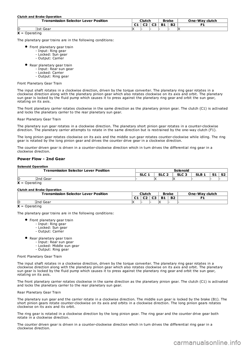
C lutch and Brake Operation
T ransmission Selector Lever PositionClutchBrakeO ne-Way clutchC1C2C3B1B2F1
D1s t GearX----X
X = Operat ing
The planetary gear t rai ns are i n t he fol lowing condit ions :
Front planetary gear t rai n- Input : Ring gear- Locked: Sun gear- Out put : Carrier
Rear pl anet ary gear t rain- Input : Rear s un gear- Locked: Carrier- Out put : Ring gear
Front Planetary Gear Train
The input s haft rot ates i n a cl ockwis e di recti on, driven by t he torque convert er. The planetary ri ng gear rotat es in aclockwi s e direct ion al ong wit h t he planet ary pi nion gear which als o rotat es clockwi se on it s axis and orbit . The pl anet arys un gear i s locked by t he fl ui d pump whi ch caus es it t o press agains t t he planetary ri ng gear and orbit t he s un gear,rot ati ng on it s axis .
The front planet ary carri er rotat es cl ockwi se in t he s ame di recti on as the pl anet ary pi nion gear. The clut ch (C1) i s act ivatedand locks the pl anet ary carrier t o t he rear planetary s un gear.
Rear Pl anet ary Gear Trai n
The planetary s un gear rotat es in a cl ockwi se direct ion. The pl anet ary short pi nion gear rot at es i n a count er-clockwi sedirect ion. The planetary carri er at t empt s t o rotat e in the s ame di recti on but is rest rai ned by the one-way clutch (F1).
The long pi ni on gear rotat es clockwi s e on it s axis and the middle s un gear rot ates count er-clockwi se whil e idl ing. The ri nggear i s rot ated by the l ong pinion gear and dri ves the counter dri ve gear i n a clockwis e di recti on.
The count er driven gear is driven in a count er-cl ockwi se direct ion which i n t urn drives t he different ial ri ng gear i n aclockwi s e direct ion.
Power Flow - 2nd G ear
Solenoid OperationT ransmission Selector Lever PositionSolenoid
SLC 1SLC 2SLC 3SLB 1S1S2
D2nd Gear-XX---X = Operat ing
C lutch and Brake Operation
T ransmission Selector Lever PositionClutchBrakeO ne-Way clutchC1C2C3B1B2F1
D2nd GearX--X--
X = Operat ing
The planetary gear t rai ns are i n t he fol lowing condit ions :
Front planetary gear t rai n- Input : Ring gear- Locked: Sun gear- Out put : Carrier
Rear pl anet ary gear t rain- Input : Rear s un gear- Locked: Middle sun gear- Out put : Ring gear
Front Planetary Gear Train
The input s haft rot ates i n a cl ockwis e di recti on, driven by t he torque convert er. The planetary ri ng gear rotat es in aclockwi s e direct ion al ong wit h t he planet ary pi nion gear which als o rotat es clockwi se on it s axis and orbit . The pl anet arys un gear i s locked by t he fl ui d pump whi ch caus es it t o press agains t t he planetary ri ng gear and orbit t he s un gear,rot ati ng on it s axis .
The front planet ary carri er rotat es cl ockwi se in t he s ame di recti on as the pl anet ary pi nion gear. The clut ch (C1) i s act ivatedand locks the pl anet ary carrier t o t he rear planetary s un gear.
Rear Pl anet ary Gear Trai n
The planetary s un gear and t he carrier rot ate i n a cl ockwis e di recti on. The middle sun gear is locked by t he brake (B1). Thes hort pinion gears rot ate counter-clockwis e on i ts axi s and orbit s i n a clockwis e direct ion. The l ong pi nion gears rotat esclockwi s e on it s axis and it s orbit .
The ri ng gear is rotat ed in a cl ockwi se direct ion by t he long pi ni on gear. The ring gear and the counter dri ve gear bot hrot ate in a cl ockwi se di recti on.
The count er driven gear is driven in a count er-cl ockwi se direct ion which i n t urn drives t he different ial ri ng gear i n aclockwi s e direct ion.
Page 1287 of 3229

• NOTE: Engine braking is avail abl e when t hi s gear is s elected.
Power Flow - 3rd Gear
Solenoid Operation
T ransmission Selector Lever PositionSolenoid
SLC 1SLC 2SLC 3SLB 1S1S2D3rd Gear-X-X--
X = Operat ing
C lutch and Brake OperationT ransmission Selector Lever PositionClutchBrakeO ne-Way clutch
C1C2C3B1B2F1
D3rd GearX--X--X = Operat ing
The planetary gear t rai ns are i n t he fol lowing condit ions :
Front planetary gear t rai n- Input : Ring gear- Locked: Sun gear- Out put : Carrier
Rear pl anet ary gear t rain- Input : Middle sun gear- Locked: -- Out put : Ring gear
Front Planetary Gear Train
The input s haft rot ates i n a cl ockwis e di recti on, driven by t he torque convert er. The planetary ri ng gear rotat es in aclockwi s e direct ion al ong wit h t he planet ary pi nion gear which als o rotat es clockwi se on it s axis and orbit . The pl anet arys un gear i s locked by t he fl ui d pump whi ch caus es it t o press agains t t he planetary ri ng gear and orbit t he s un gear,rot ati ng on it s axis .
The front planet ary carri er rotat es cl ockwi se in t he s ame di recti on as the pl anet ary pi nion gear. The clut ch (C1) i s act ivatedand locks the pl anet ary carrier t o t he rear planetary s un gear. Clut ch (C3) i s als o acti vat ed and locks the carri er t o t hemi ddl e s un gear.
Rear Pl anet ary Gear Trai n
The planetary s hort pinion gear and t he long pini on gear are engaged whi ch caus es both pi nion gears t o l ock due t o t hedifferent rotat ional di recti ons . Torque from the sun gear and mi ddl e s un gear is t rans mit t ed to the pl anet ary ring gearwhich rotat es cl ockwi se in t he s ame di recti on as the pl anet ary carrier.
The count er drive gear rot ates i n a clockwis e di recti on wit h t he ri ng gear.
The count er driven gear is rotat ed in a count er-cl ockwis e di recti on which i n t urn drives the di fferenti al ri ng gear i n aclockwi s e direct ion.
• NOTE: Engine braking is avail abl e when t hi s gear is s elected.
Power Flow - 4th Gear
Solenoid OperationT ransmission Selector Lever PositionSolenoid
SLC 1SLC 2SLC 3SLB 1S1S2
D4t h Gear--XX--X = Operat ing
C lutch and Brake Operation
T ransmission Selector Lever PositionClutchBrakeO ne-Way clutchC1C2C3B1B2F1
D4t h GearXX----
X = Operat ing
The planetary gear t rai ns are i n t he fol lowing condit ions :
Front planetary gear t rai n- Input : Ring gear- Locked: Sun gear- Out put : Carrier
Rear pl anet ary gear t rain- Input : Rear s un gear, Carrier- Locked: -- Out put : Ring gear
Front Planetary Gear Train
The input s haft rot ates i n a cl ockwis e di recti on, driven by t he torque convert er. The planetary ri ng gear rotat es in aclockwi s e direct ion al ong wit h t he planet ary pi nion gear which als o rotat es clockwi se on it s axis and orbit . The pl anet arys un gear i s locked by t he fl ui d pump whi ch caus es it t o press agains t t he planetary ri ng gear and orbit t he s un gear,rot ati ng on it s axis .
Page 1288 of 3229

The front planet ary carri er rotat es cl ockwi se in t he s ame di recti on as the pl anet ary pi nion gear. The clut ch (C1) i s act ivatedand locks the pl anet ary carrier t o t he rear planetary s un gear. The int ermediat e s haft rotat es in t he s ame di recti on as theinput s haft. Cl utch (C2) is al so act ivated rotat es in the s ame di recti on as t he int ermediat e s haft .
Rear Pl anet ary Gear Trai n
The planetary carri er rot at es in a clockwis e direct ion wit h the intermediat e s haft. The s hort pi ni on gear rotat es clockwi s eon i ts axis and orbit s at a fast er s peed t han t he sun gear. The long pini on gear rotat es counter-clockwis e on i ts axi s andorbi t. The rot ati on of the ri ng gear i s in a clockwi s e direct ion and i s s lower than t he rotat ion of t he carri er due t o t he l ongpinion gear's rotat ion i s count eract ed by t he planetary carri er.
The count er drive gear rot ates i n a clockwis e di recti on wit h t he ri ng gear.
The count er driven gear is rotat ed in a count er-cl ockwis e di recti on which i n t urn drives the di fferenti al ri ng gear i n aclockwi s e direct ion.
• NOTE: Engine braking is avail abl e when t hi s gear is s elected.
Power Flow - 5th Gear
Solenoid Operation
T ransmission Selector Lever PositionSolenoid
SLC 1SLC 2SLC 3SLB 1S1S2D5t h GearX--X--
X = Operat ing
C lutch and Brake Operation
T ransmission Selector Lever PositionClutchBrakeO ne-Way clutchC1C2C3B1B2F1
D5t h Gear-XX---
X = Operat ing
The planetary gear t rai ns are i n t he fol lowing condit ions :
Front planetary gear t rai n- Input : Ring gear- Locked: Sun gear- Out put : Carrier
Rear pl anet ary gear t rain- Input : Middle sun gear- Locked: -- Out put : Ring gear
Front Planetary Gear Train
The input s haft rot ates i n a cl ockwis e di recti on, driven by t he torque convert er. The planetary ri ng gear rotat es in aclockwi s e direct ion al ong wit h t he planet ary pi nion gear which als o rotat es clockwi se on it s axis and orbit . The pl anet arys un gear i s locked by t he fl ui d pump whi ch caus es it t o press agains t t he planetary ri ng gear and orbit t he s un gear,rot ati ng on it s axis .
The front planet ary carri er rotat es cl ockwi se in t he s ame di recti on as the pl anet ary pi nion gear. The clut ch (C3) i s act ivatedand locks the pl anet ary carrier t o t he rear planetary mi ddl e s un gear. The int ermediat e s haft rotat es in t he s ame di recti onas t he input s haft. Cl ut ch (C2) i s als o act ivated and rotat es in t he s ame di recti on as the intermediat e s haft.
Rear Pl anet ary Gear Trai n
The mi ddl e s un gear rotat es clockwi se in the s ame di recti on as clutch (C3). The decelerat ion of t he front pl anet ary gears lows t he s peed of t he i nput s haft . The int ermediat e s haft rot ates clockwis e i n t he s ame direct ion as t he i nput s haft . Theplanetary carri er al s o rot ates clockwis e i n t he s ame direct ion as t he i nt ermedi ate shaft .
The long pi ni on gear rotat es clockwi s e on it s axis and orbit . The carri er rotat es fas t er t han t he middle s un gear whi chcaus es t he mi ddl e pinion gear t o be cancell ed out by the speed difference. The mi ddle pini on gear orbi ts and rot at es on i tsaxis i n a clockwis e direct ion.
The planetary ri ng gear rotat es in a clockwi s e direct ion. The s peed of t he ri ng gear is fast er than t he planetary carri erbecaus e t he long pini on gear's rotat ion i s combined wi th t he planet ary carrier's s peed. The count er drive gear rot ates i n aclockwi s e direct ion wi th the ring gear.
The count er driven gear is rotat ed in a count er-cl ockwis e di recti on which i n t urn drives the di fferenti al ri ng gear i n aclockwi s e direct ion.
• NOTE: Engine braking is avail abl e when t hi s gear is s elected.
Power Flow - 6th Gear
Solenoid OperationT ransmission Selector Lever PositionSolenoid
SLC 1SLC 2SLC 3SLB 1S1S2
D6t h GearX-X---X = Operat ing
C lutch and Brake Operation
T ransmission Selector Lever PositionClutchBrakeO ne-Way clutchC1C2C3B1B2F1