2006 LAND ROVER FRELANDER 2 torque
[x] Cancel search: torquePage 1368 of 3229
Publi s hed: 11-May-2011
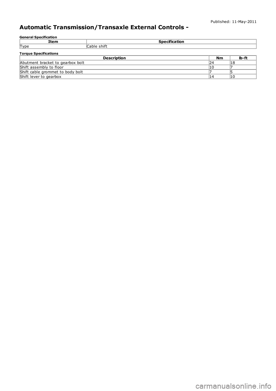
Automatic Transmission/Transaxle External Controls -
General SpecificationItemSpecification
TypeCabl e s hift
Torque Specifications
DescriptionNmlb-ft
Abutment bracket to gearbox bol t2418Shift ass embly to fl oor107
Shift cabl e grommet t o body bolt75
Shift lever to gearbox1410
Page 1370 of 3229
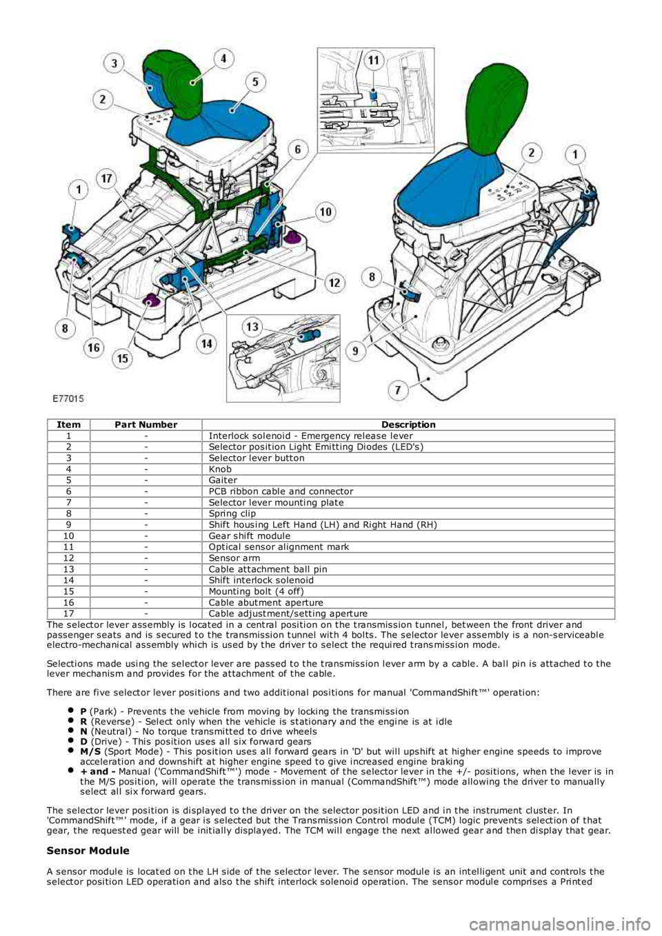
ItemPart NumberDescription
1-Interlock sol enoi d - Emergency rel eas e l ever2-Selector pos it ion Light Emi tt ing Di odes (LED's )
3-Selector l ever butt on
4-Knob5-Gait er
6-PCB ribbon cabl e and connector
7-Selector l ever mounti ng plat e8-Spri ng clip
9-Shift hous i ng Left Hand (LH) and Ri ght Hand (RH)
10-Gear s hi ft modul e11-Opt ical sens or al ignment mark
12-Sensor arm
13-Cable at t achment ball pin14-Shift int erlock s olenoid
15-Mounti ng bolt (4 off)
16-Cable abut ment aperture17-Cable adjust ment/s ett ing apert ure
The s elect or lever ass embly is l ocat ed in a cent ral posi ti on on t he t ransmis s ion t unnel , bet ween the front driver andpass enger s eats and is s ecured t o t he transmis si on t unnel wit h 4 bol ts . The s elector lever ass embly is a non-s erviceabl eelectro-mechani cal as s embly whi ch is us ed by t he dri ver t o s elect the requi red t ransmi ss i on mode.
Selecti ons made usi ng the sel ect or lever are pass ed t o t he t rans mis s ion l ever arm by a cable. A bal l pi n i s att ached t o t helever mechanis m and provides for the at tachment of t he cable.
There are fi ve s elect or lever pos i ti ons and t wo addit ional pos i ti ons for manual 'CommandShi ft ™' operati on:
P (Park) - Prevents t he vehicle from moving by locki ng the trans mi ss i onR (Revers e) - Sel ect only when the vehicle is s t ati onary and the engi ne is at i dleN (Neutral) - No torque trans mi tt ed t o dri ve wheel sD (Drive) - Thi s pos it ion us es all s ix forward gearsM/S (Sport Mode) - This pos it ion us es all forward gears in 'D' but wil l ups hift at hi gher engine s peeds to improveaccelerati on and downs hift at higher engine speed t o give i ncreased engine braki ng+ and - Manual ('CommandShi ft ™') mode - Movement of t he s elector lever in the +/- posi ti ons, when t he l ever is int he M/S pos i ti on, wi ll operate the trans mi ss i on in manual (CommandShift ™) mode all owing t he dri ver t o manuall ys elect al l si x forward gears.
The s elect or lever pos i ti on is di spl ayed t o t he dri ver on the s elector pos it ion LED and i n t he ins trument cl ust er. In'CommandShift™ ' mode, i f a gear i s s elected but t he Trans mis s ion Control modul e (TCM) logic prevent s s el ect ion of t hatgear, t he request ed gear will be init iall y dis played. The TCM wil l engage t he next al lowed gear and then di spl ay that gear.
Sensor Module
A s ens or modul e is locat ed on t he LH s ide of t he s elector lever. The s ens or modul e is an int el li gent unit and controls t hes elect or posi ti on LED operati on and als o t he s hift interlock s olenoi d operat ion. The sens or modul e compri ses a Pri nt ed
Page 1390 of 3229
Publi s hed: 11-May-2011
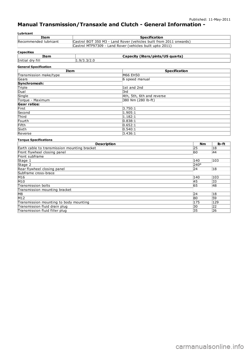
Manual Transmission/Transaxle and Clutch - General Information -
LubricantItemSpecification
Recommended lubri cantCas trol BOT 350 M3 - Land Rover (vehicles buil t from 2011 onwards )
Cas trol MTF97309 - Land Rover (vehi cl es bui lt upt o 2011)
C apacities
ItemCapacity (liters/pints/US quarts)Init ial dry fil l1.9/3.3/2.0
General Specification
ItemSpecification
Trans mi ss ion make/typeM66 EH50Gears6 s peed manual
Synchromesh:
Tri ple1s t and 2ndDual3rd
Single4t h, 5th, 6t h and revers e
Torque - Maximum380 Nm (280 lb-ft )Gear ratios:
Firs t3.750:1
Second1.905:1Third1.182:1
Fourt h0.838:1
Fifth0.652:1Sixt h0.540:1
Revers e3.436:1
Torque Specifications
DescriptionNmlb-ftEart h cable t o t rans mis s ion mount ing bracket2518
Front flywheel clos ing panel6044
Front s ubframeSt age 1140103
St age 2240°
Rear fl ywheel clos ing panel2418Subframe cros s -brace
M16140103
M104533Trans mi ss ion bol ts6548
Trans mi ss ion mount ing bracket
M82418M128059
Trans mi ss ion mount ing to body mount ing175129
Trans mi ss ion fl ui d drai n plug3022Trans mi ss ion fl ui d fill er plug3526
Page 1391 of 3229
Publi s hed: 11-May-2011
Manual Transmission/Transaxle and Clutch - General Information - Manual
Transmission and Clutch
Des cript ion and Operat ion
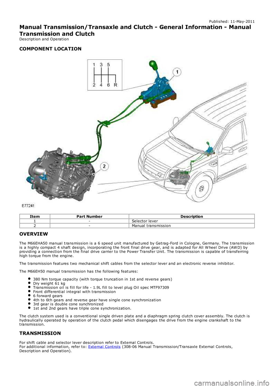
COMPONENT LOCATION
ItemPart NumberDescription1-Selector lever
2-Manual t rans mi ss ion
OVERVIEW
The M66EHA50 manual t rans mis s ion i s a 6 speed unit manufact ured by Get rag-Ford in Col ogne, Germany. The t rans mis s ionis a highly compact 4 s haft desi gn, incorporati ng t he front final dri ve gear, and is adapted for All W heel Dri ve (AW D) byprovidi ng a connecti on from t he final drive carrier t o t he Power Transfer Uni t. The t rans mi ss i on is capabl e of t ransferringhigh t orque from the engi ne.
The t ransmis s ion feat ures t wo mechanical s hift cabl es from t he s elector l ever and an electronic reverse inhibit or.
The M66EH50 manual t rans mis s ion has t he fol lowi ng feat ures:
380 Nm torque capaci ty (wi th torque truncati on in 1st and revers e gears )Dry weight 61 kgTrans mis s ion oi l is fil l for li fe - 1.9L fill t o l evel plug Oi l s pec MTF97309Front different ial int egral wit h t rans mis s ion6 forward gears4th to 6t h gears and revers e gear have s i ngl e cone synchronizati on3rd gear i s doubl e cone synchronized1s t and 2nd gears have triple cone s ynchroni zat ion.
The clutch s ys tem used is a convent ional s ingle driven plat e and a di aphragm s pri ng cl utch cover as s embly. The cl utch i shydraulicall y operated by operat ion of t he clut ch pedal which di sengages the drive from the engine cranks haft t o t het ransmis s ion.
TRANSMISSION
For shi ft cabl e and s elector l ever descripti on refer to Ext ernal Cont rol s.For addit ional informat ion, refer t o: Ext ernal Control s (308-06 Manual Trans mi ss i on/Trans axl e External Controls ,Des cript ion and Operat ion).
Page 1394 of 3229
16-Ball li mit er for gear sel ect or
The t ransmis s ion i s operated by two shi ft cabl es which are att ached t o t he s elector lever. Movement of the s elect or l everis pas s ed via t he cables t o t wo lever mechanis ms on the top of t he t ransmis s ion. The levers operat e a s hift cont rolmechani sm wi thin the trans mi ss i on to sel ect t he reques ted gear rat io.
The s hift control mechanis m is locat ed at t he front of t he t rans mis s ion and t rans fers the shi ft cable movement int o gears elect ions .
The s hift control mechanis m is a one-piece as sembl y which i s ret ained i n the trans mis si on hous i ng wit h 4 bol ts . The s hi ftcont rol mechani s m moves t he upper and l ower gear s elect or forks vi a t he lat eral and longit udi nal l evers on t he t op of thes hift control mechanis m. There are 2 upper s elector forks and 2 l ower s elector forks as fol lows :
The 2 upper gear s elector forks are us ed t o engage revers e, 1st or 2nd gearsThe 2 l ower gear s elect or forks are us ed t o engage 3rd, 4th, 5th and 6th gears .
The 4 s elector forks t rans fer movement from t he s hi ft control mechanis m to the relevant shi ft coupl ing s leeve. The shi ftforks are mount ed in bearings in the trans mi ss i on cas e.
Two carrier plat es trans fer torque from t he longit udi nal l ever t o t he s lidi ng gear selectors . The carriers are locat ed and runin a groove i n the gear s elector plat e.
The carri er plates can move verti call y between 4 pos i ti ons . The different gears are s elected from one of t he 4 posi ti ons asfol lows :
Uppermos t posi ti on - gear s elect or s elects revers e gearSecond uppermos t posi ti on - gear sel ect or sel ect s 1st and 2nd gearsSecond l owes t pos it ion - gear s el ect or s el ect s 5t h and 6th gearsLowes t pos it ion - gear s el ect or s el ect s 3rd and 4th gears.
The s hift control mechanis m has two s prings t hat return t he s el ect or lever to the neutral pos it ion.
Trans mis s ion Shi ft Selector Shaft s
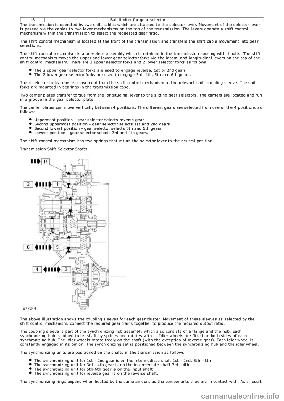
The above ill ust rat ion s hows t he coupl ing s leeves for each gear clus t er. Movement of t hes e sl eeves as s elected by thes hift control mechanis m, connect t he required gear t rai ns toget her t o produce t he required out put rat io.
The coupl ing s leeve is part of the synchronizing hub as s embly whi ch al s o cons is t s of a flange and the hub. Eachs ynchronizi ng hub is joined t o it s s haft by s pli nes and rot at es wi th it . Idler wheels are fit ted on bot h s ides of eachs ynchronizi ng hub. The i dl er wheel s rot ate freel y on t he s haft (wit h the excepti on of revers e gear). Each i dler wheel i scons t ant ly engaged in it s pinion. The s ynchronizi ng s et i s pos it ioned bet ween t he s ynchronizing hub and the i dler wheel .
The s ynchronizi ng uni ts are pos it ioned on t he s hafts in t he t rans mis s ion as foll ows:
The s ynchronizi ng uni t for 1s t - 2nd gear i s on t he int ermedi at e s haft 1s t - 2nd, 5th - 6t hThe s ynchronizi ng uni t for 3rd - 4th gear i s on t he int ermediat e s haft 3rd - 4thThe s ynchronizi ng uni t for 5t h-6th gear i s on t he input s haftThe s ynchronizi ng uni t for reverse gear i s on t he revers e s haft .
The s ynchronizi ng ri ngs expand when heated by t he s ame amount as t he components they are in contact wit h. As a resul t
Page 1400 of 3229
s ynchronizi ng hub towards the revers e gear i dler gear.
The coupl ing s leeve and s ynchronizi ng hub lock t he revers e gear idler gear at the revers e s haft.
The t orque of the engine is t rans ferred via the cl ut ch t o the input shaft. The 1s t gear on t he i nput s haft t rans fers power t ot he 1st gear idl er gear. The power is then t rans ferred t o t he revers e gear idl er gear and then t o t he reverse gear coupl ings leeve. From t here power is trans ferred to t he i nt ermedi ate s haft 1s t - 2nd and 5t h - 6th and to the final dri ve which i nt urn t rans fers power t o t he ring gear. The ring gear is connect ed to the drive s hafts t hrough the di fferenti al.
Differential
The different ial dis t ribut es dri ve from t he t ransmis s ion equally bet ween t he LH and RH front half s haft s and als o provi desdri ve torque to the rear di fferenti al vi a t he power t rans fer unit .
The different ial is locat ed at t he rear of the trans mi ss i on hous ing. Both s ides of the di fferenti al are connected to t he LHand RH drive s haft s, s upplying t orque t o t he front wheel s The different ial is als o connected t o t he Power Transfer Unit viaa s pli ned shaft to the RH s ide of t he trans mi s si on, s upplying t orque t o t he rear driveline.
Reverse Switch
The revers e s wi tch i s located i n t he front of the t rans mis s ion cas ing, above t he 1s t gear det ect ion s wi tch. The swi tch i sus ed by the Ant i-lock Brake Sys tem (ABS) module for Hil l Descent Cont rol (HDC) and als o for revers ing l amp operati on.
1st Gear Position Switch
The 1s t gear s wit ch is locat ed on t he front of the t rans mi ss ion cas ing, below t he reverse swit ch. The s wit ch is us ed by t heABS module for HDC.
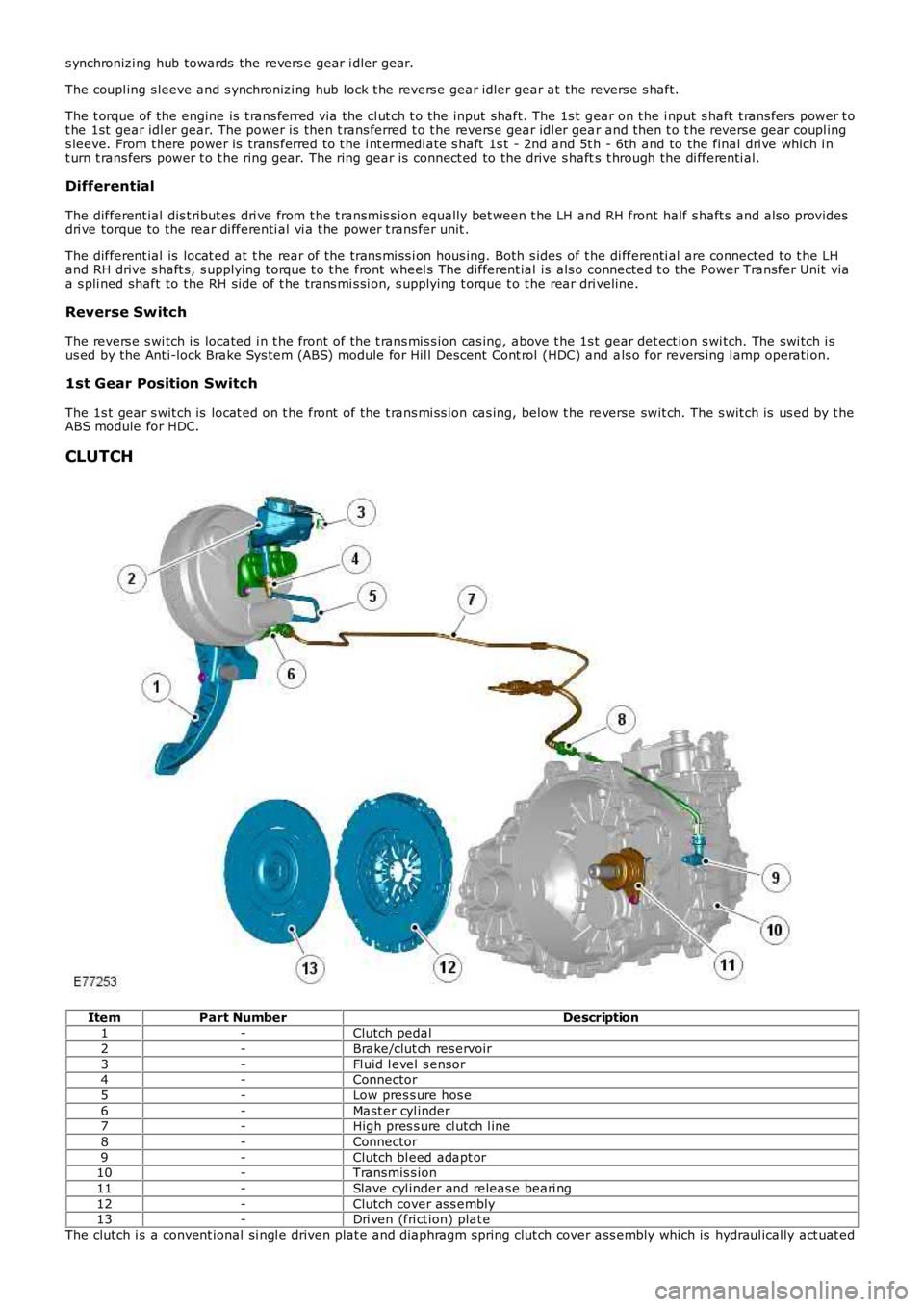
CLUTCH
ItemPart NumberDescription1-Clutch pedal
2-Brake/clut ch res ervoir
3-Fl uid l evel s ensor4-Connector
5-Low pres s ure hos e
6-Mast er cyl inder7-High pres s ure cl utch l ine
8-Connector
9-Clutch bl eed adapt or10-Transmis s ion
11-Slave cyl inder and releas e beari ng
12-Clutch cover as s embly13-Dri ven (fri ct ion) plat e
The clutch i s a convent ional si ngl e driven plat e and diaphragm spring clut ch cover ass embly which is hydraul ically act uat ed
Page 1401 of 3229
from the clut ch pedal .
The main components of t he clut ch are t he clut ch cover as s embly (pres s ure pl ate), the engine flywheel and the drivenplat e (fricti on plate). Toget her wit h fl ywheel and dri ven plate, t he clutch cover forms a fri ct ion s ys tem and is mount ed t ot he fl ywheel by bolt s in the hous ing.
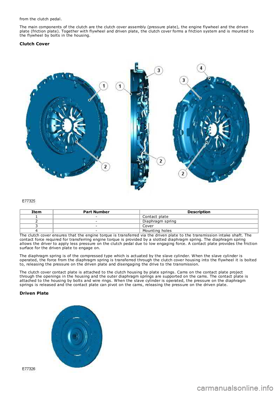
Clutch Cover
ItemPart NumberDescription
1-Cont act plat e2-Di aphragm s pri ng
3-Cover
4-Mount ing holesThe clutch cover ens ures t hat the engine torque i s t rans ferred via the driven plat e t o t he trans mi s si on int ake shaft. Thecont act force requi red for trans ferring engine t orque i s provided by a sl ott ed diaphragm spring. The diaphragm s pri ngall ows the driver to appl y les s pres s ure on the cl ut ch pedal due t o l ow engagi ng force. A contact plat e provides t he frict ions urface for the driven plat e t o engage on.
The diaphragm spring i s of the compres s ed t ype which is act uat ed by t he s lave cyl inder. W hen the s l ave cyli nder i soperated, t he force from t he diaphragm spring i s t ransferred t hrough the cl ut ch cover housi ng int o t he fl ywheel it i s bolt edt o, releas ing t he pres s ure on t he dri ven plate and dis engaging the drive t o t he transmis si on.
The clutch cover contact plat e is att ached t o t he clutch hous ing by pl at e s pri ngs . Cams on the contact plat e projectt hrough the openings i n the hous ing and t he outer di aphragm s prings are s upported on the cams . The cont act pl at e i satt ached t o t he housi ng by bolt s and wire rings . W hen t he s lave cyl inder is operat ed, t he pres s ure on the di aphragms prings i s rel eas ed and t he cont act pl ate can pi vot on the cams , rel eas ing the pres sure on the driven plat e.
Driven Plate
Page 1402 of 3229
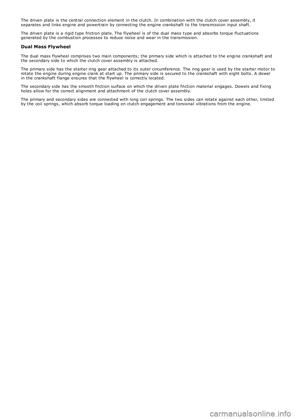
The dri ven pl ate is t he cent ral connecti on element i n the cl utch. In combi nat ion wi th the cl ut ch cover as sembl y, its eparates and l inks engi ne and powert rain by connect ing the engine cranks haft t o t he trans mi s si on input s haft.
The dri ven pl ate is a ri gi d t ype fricti on plat e. The flywheel is of t he dual mas s t ype and abs orbs torque fluct uat ionsgenerated by t he combust ion proces s es to reduce noi s e and wear in t he t rans mis s ion.
Dual Mass Flywheel
The dual mas s flywheel compris es t wo main components ; t he pri mary s i de which i s att ached t o t he engi ne crankshaft andt he secondary s ide t o whi ch the clut ch cover as sembl y is at t ached.
The pri mary si de has the st art er ri ng gear at tached to it s outer circumference. The ring gear is us ed by t he s tarter mot or torot ate the engine during engine crank at s t art up. The primary s ide is s ecured t o t he cranks haft wi th eight bol ts . A dowelin the cranks haft flange ens ures that t he fl ywheel is correctl y located.
The s econdary s ide has the s moot h frict ion s urface on which t he dri ven pl ate fri cti on material engages . Dowel s and fixingholes all ow for the correct al ignment and att achment of the cl utch cover as s embl y.
The pri mary and secondary s ides are connect ed wi th l ong coi l springs . The two si des can rotat e agains t each ot her, li mi tedby t he coi l springs , whi ch absorb t orque loading on cl ut ch engagement and t ors ional vi brati ons from t he engine.