Page 2067 of 5267
CLEANING
CLEANING AND INSPECTION
1. Before cleaning, check for leaks, damage and
cracks.
2. Clean cylinder head and oil passages.
3. Check cylinder head for flatness.
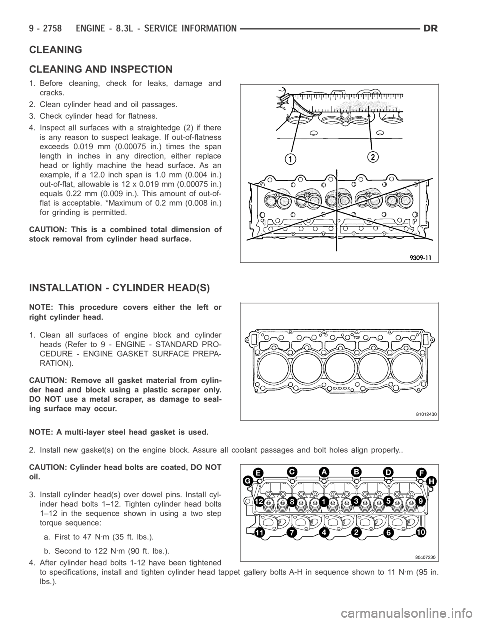
4. Inspect all surfaces with a straightedge (2) if there
is any reason to suspect leakage. If out-of-flatness
exceeds 0.019 mm (0.00075 in.) times the span
length in inches in any direction, either replace
head or lightly machine the head surface. As an
example, if a 12.0 inch span is 1.0 mm (0.004 in.)
out-of-flat, allowable is 12 x 0.019 mm (0.00075 in.)
equals 0.22 mm (0.009 in.). This amount of out-of-
flat is acceptable. *Maximum of 0.2 mm (0.008 in.)
for grinding is permitted.
CAUTION: This is a combined total dimension of
stock removal from cylinder head surface.
INSTALLATION - CYLINDER HEAD(S)
NOTE: This procedure covers either the left or
right cylinder head.
1. Clean all surfaces of engine block and cylinder
heads (Refer to 9 - ENGINE - STANDARD PRO-
CEDURE - ENGINE GASKET SURFACE PREPA-
RATION).
CAUTION: Remove all gasket material from cylin-
der head and block using a plastic scraper only.
DO NOT use a metal scraper, as damage to seal-
ing surface may occur.
NOTE: A multi-layer steel head gasket is used.
2. Install new gasket(s) on the engine block. Assure all coolant passages and bolt holes align properly..
CAUTION: Cylinder head bolts are coated, DO NOT
oil.
3. Install cylinder head(s) over dowel pins. Install cyl-
inder head bolts 1–12. Tighten cylinder head bolts
1–12 in the sequence shown in using a two step
torque sequence:
a. Firstto47Nꞏm(35ft.lbs.).
b. Second to 122 Nꞏm (90 ft. lbs.).
4. After cylinder head bolts 1-12 have been tightened
to specifications, install and tighten cylinder head tappet gallery bolts A-H in sequence shown to 11 Nꞏm (95 in.
lbs.).
Page 2068 of 5267
5. Inspect the push rods. Replace worn or bent push
rods as necessary.
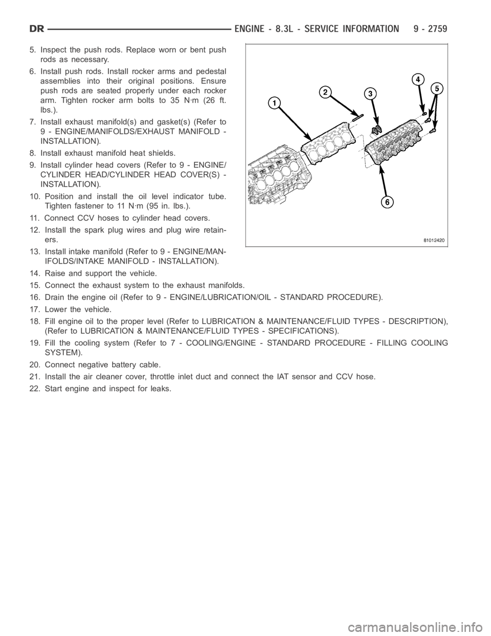
6. Install push rods. Install rocker arms and pedestal
assemblies into their original positions. Ensure
push rods are seated properly under each rocker
arm.Tightenrockerarmboltsto35Nꞏm(26ft.
lbs.).
7. Install exhaust manifold(s) and gasket(s) (Refer to
9 - ENGINE/MANIFOLDS/EXHAUST MANIFOLD -
INSTALLATION).
8. Install exhaust manifold heat shields.
9. Install cylinder head covers (Refer to 9 - ENGINE/
CYLINDER HEAD/CYLINDER HEAD COVER(S) -
INSTALLATION).
10. Position and install the oil level indicator tube.
Tighten fastener to 11 Nꞏm (95 in. lbs.).
11. Connect CCV hoses to cylinder head covers.
12. Install the spark plug wires and plug wire retain-
ers.
13. Install intake manifold (Refer to 9 - ENGINE/MAN-
IFOLDS/INTAKE MANIFOLD - INSTALLATION).
14. Raise and support the vehicle.
15. Connect the exhaust systemto the exhaust manifolds.
16. Drain the engine oil (Refer to 9 - ENGINE/LUBRICATION/OIL - STANDARD PROCEDURE).
17. Lower the vehicle.
18. Fill engine oil to the proper level (Refer to LUBRICATION & MAINTENANCE/FLUID TYPES - DESCRIPTION),
(Refer to LUBRICATION & MAINTENANCE/FLUID TYPES - SPECIFICATIONS).
19. Fill the cooling system (Refer to 7 - COOLING/ENGINE - STANDARD PROCEDURE - FILLING COOLING
SYSTEM).
20. Connect negative battery cable.
21. Install the air cleaner cover, throttle inlet duct and connect the IAT sensor and CCV hose.
22. Start engine and inspect for leaks.
Page 2069 of 5267
COVER(S)-CYLINDER HEAD
REMOVAL
LEFT CYLINDER HEAD COVER
NOTE: Care must be taken to protect the cylinder
head cover powder coating from scrapes and
abrasions.
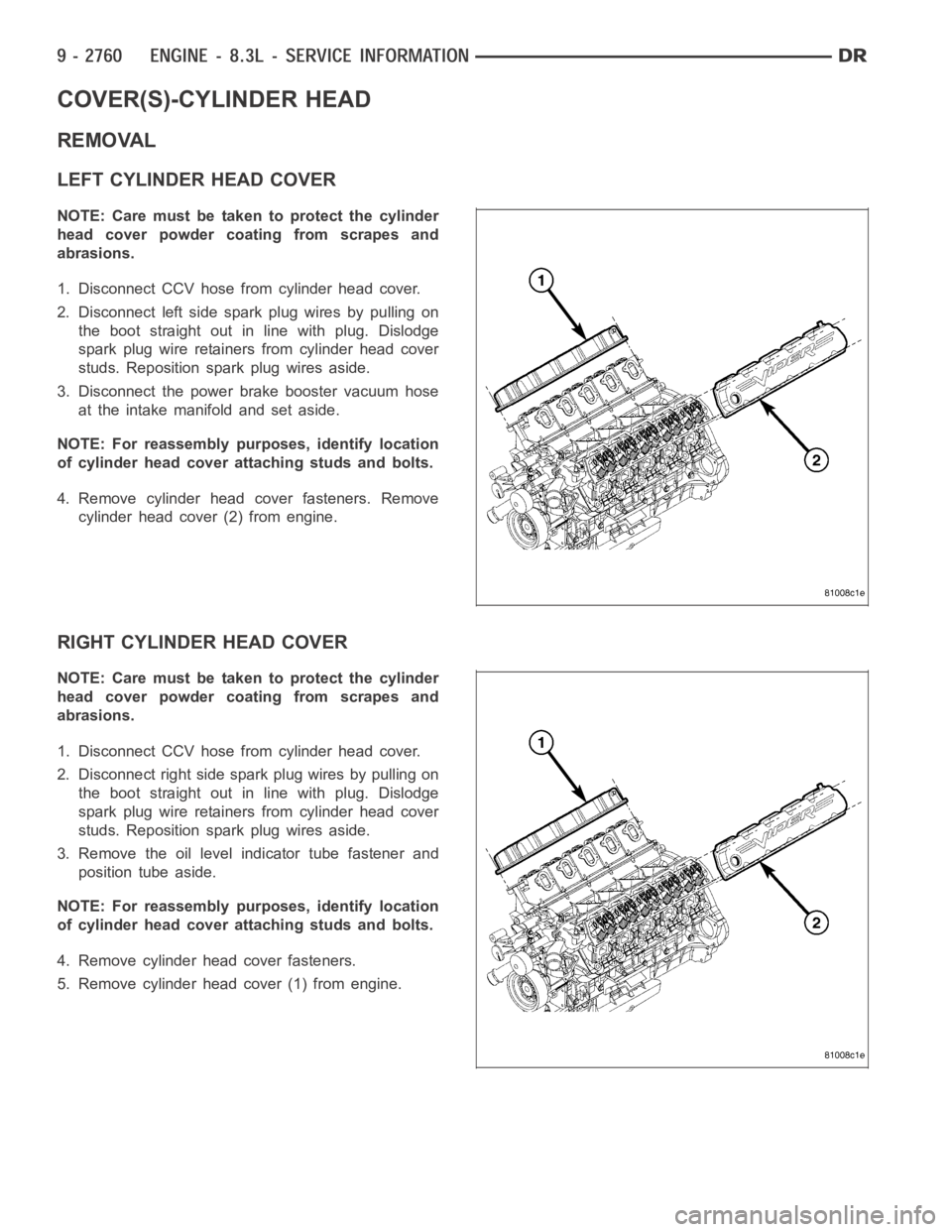
1. Disconnect CCV hose from cylinder head cover.
2. Disconnect left side spark plug wires by pulling on
the boot straight out in line with plug. Dislodge
spark plug wire retainers from cylinder head cover
studs. Reposition spark plug wires aside.
3. Disconnect the power brake booster vacuum hose
at the intake manifold and set aside.
NOTE: For reassembly purposes, identify location
of cylinder head cover attaching studs and bolts.
4. Remove cylinder head cover fasteners. Remove
cylinder head cover (2) from engine.
RIGHT CYLINDER HEAD COVER
NOTE: Care must be taken to protect the cylinder
head cover powder coating from scrapes and
abrasions.
1. Disconnect CCV hose from cylinder head cover.
2. Disconnect right side spark plug wires by pulling on
the boot straight out in line with plug. Dislodge
spark plug wire retainers from cylinder head cover
studs. Reposition spark plug wires aside.
3. Remove the oil level indicator tube fastener and
position tube aside.
NOTE: For reassembly purposes, identify location
of cylinder head cover attaching studs and bolts.
4. Remove cylinder head cover fasteners.
5. Remove cylinder head cover (1) from engine.
Page 2071 of 5267
ARMS-ROCKER
REMOVAL
NOTE: Before replacing parts, inspect all related
valvetrain components for damage to prevent
engine misfire.
1. Remove cylinder head cover(s) (Refer to 9 -
ENGINE/CYLINDER HEAD/CYLINDER HEAD
COVER(S) - REMOVAL).
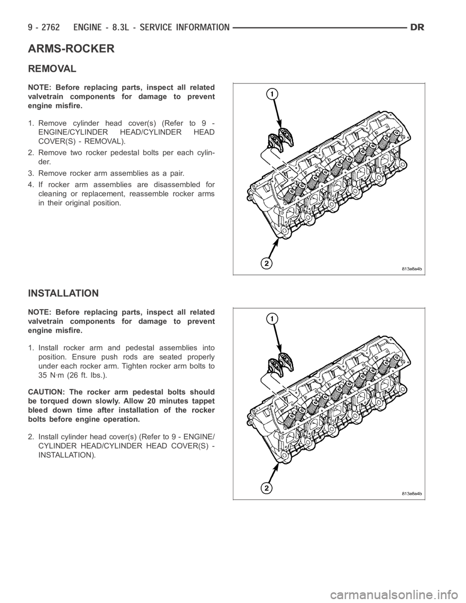
2. Remove two rocker pedestal bolts per each cylin-
der.
3. Remove rocker arm assemblies as a pair.
4. If rocker arm assemblies are disassembled for
cleaning or replacement, reassemble rocker arms
in their original position.
INSTALLATION
NOTE: Before replacing parts, inspect all related
valvetrain components for damage to prevent
engine misfire.
1. Install rocker arm and pedestal assemblies into
position. Ensure push rods are seated properly
under each rocker arm. Tighten rocker arm bolts to
35 Nꞏm (26 ft. lbs.).
CAUTION: The rocker arm pedestal bolts should
be torqued down slowly. Allow 20 minutes tappet
bleed down time after installation of the rocker
bolts before engine operation.
2. Install cylinder head cover(s) (Refer to 9 - ENGINE/
CYLINDER HEAD/CYLINDER HEAD COVER(S) -
INSTALLATION).
Page 2072 of 5267
SPRINGS/SEALS-VALVE
DIAGNOSIS AND TESTING
VA LV E S P R I N G T E S T I N G
The valve springs should be tested whenever
removed for inspection, reconditioning, or replace-
ment.
1. Obtain specifications for spring tension at specified
spring length (Refer to 9 - ENGINE - SPECIFICA-
TIONS).
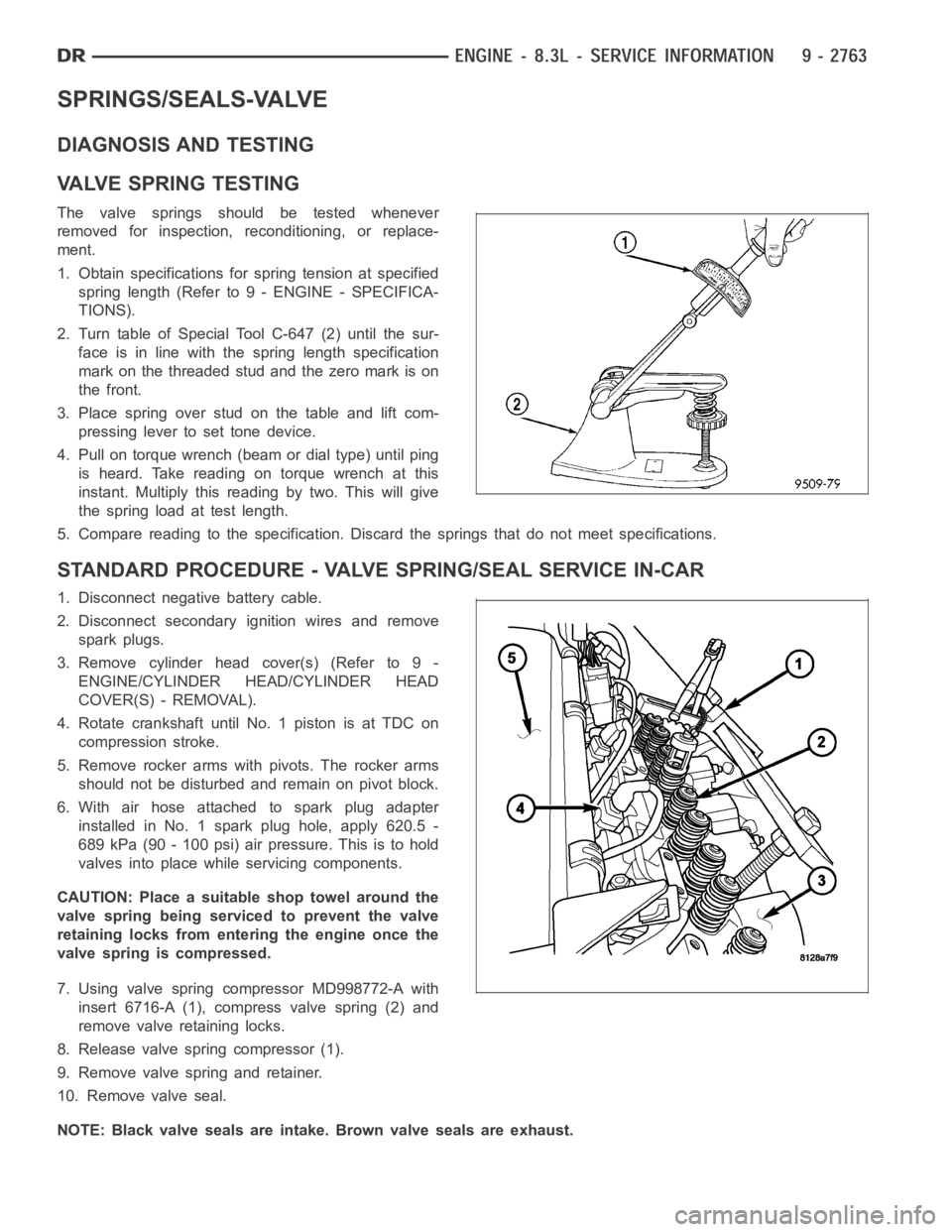
2. Turn table of Special Tool C-647 (2) until the sur-
face is in line with the spring length specification
mark on the threaded stud and the zero mark is on
the front.
3.Placespringoverstudonthetableandliftcom-
pressing lever to set tone device.
4. Pull on torque wrench (beam or dial type) until ping
is heard. Take reading on torque wrench at this
instant. Multiply this reading by two. This will give
the spring load at test length.
5. Compare reading to the specification. Discard the springs that do not meet specifications.
STANDARD PROCEDURE - VALVE SPRING/SEAL SERVICE IN-CAR
1. Disconnect negative battery cable.
2. Disconnect secondary ignition wires and remove
spark plugs.
3. Remove cylinder head cover(s) (Refer to 9 -
ENGINE/CYLINDER HEAD/CYLINDER HEAD
COVER(S) - REMOVAL).
4. Rotate crankshaft until No. 1 piston is at TDC on
compression stroke.
5. Remove rocker arms with pivots. The rocker arms
should not be disturbed and remain on pivot block.
6. With air hose attached to spark plug adapter
installed in No. 1 spark plug hole, apply 620.5 -
689 kPa (90 - 100 psi) air pressure. This is to hold
valves into place while servicing components.
CAUTION: Place a suitable shop towel around the
valve spring being serviced to prevent the valve
retaining locks from entering the engine once the
valve spring is compressed.
7. Using valve spring compressor MD998772-A with
insert 6716-A (1), compress valve spring (2) and
remove valve retaining locks.
8. Release valve spring compressor (1).
9. Remove valve spring and retainer.
10. Remove valve seal.
NOTE: Black valve seals are intake. Brown valve seals are exhaust.
Page 2073 of 5267
11. The intake and exhaust valve stem seals should be pushed firmly and squarely over the valve guide using the
valve stem as guide. Push seal against top of guide. When installing the valve retainer locks, compress the
springonly enoughto install the locks.
CAUTION: Do not pinch seal between retainer and top of valve guide.
12. Follow the same procedure on the remaining 9 cylinders.Make sure piston is at TDC on the cylinder the
valve spring is being removed.
13. Remove spark plug adapter tool.
14. Install rocker arm and pedestal assemblies. Ensure push rods are seated properly under each rocker arm.
Tightenrockerarmboltsto35Nꞏm(26ft.lbs.).
15. Install cylinder head covers (Refer to 9 - ENGINE/CYLINDER HEAD/CYLINDERHEADCOVER(S)-INSTAL-
LATION).
16. Install spark plugs and connect secondary ignition wires.
17. Connect negative battery cable.
REMOVAL
NOTE: Before replacing parts, inspect all related
valvetrain components for damage to prevent
engine misfire.
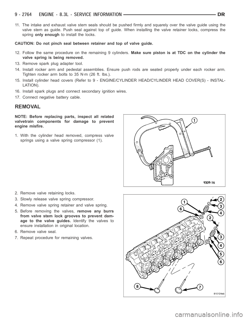
1. With the cylinder head removed, compress valve
springs using a valve spring compressor (1).
2. Remove valve retaining locks.
3. Slowly release valve spring compressor.
4. Remove valve spring retainer and valve spring.
5. Before removing the valves,remove any burrs
from valve stem lock grooves to prevent dam-
age to the valve guides.Identify the valves to
ensure installation in original location.
6. Remove valve seal.
7. Repeat procedure for remaining valves.
Page 2074 of 5267
INSTALLATION
NOTE: Before replacing parts, inspect all related
valvetrain components for damage to prevent
engine misfire.
NOTE: Black valve seals are intake. Brown valve
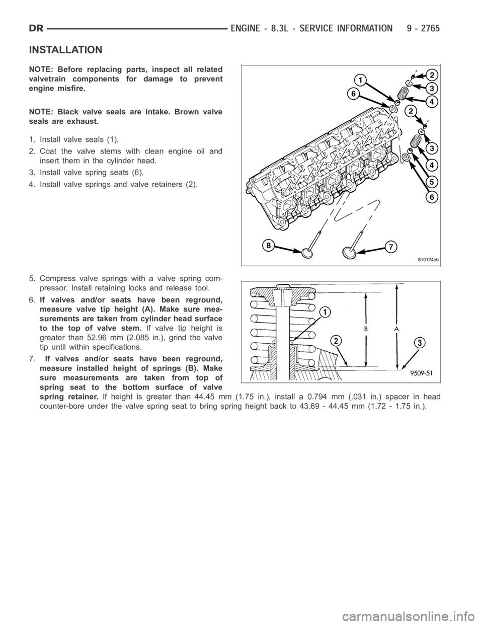
seals are exhaust.
1. Install valve seals (1).
2. Coat the valve stems with clean engine oil and
insert them in the cylinder head.
3. Install valve spring seats (6).
4. Install valve springs and valve retainers (2).
5. Compress valve springs with a valve spring com-
pressor. Install retaining locks and release tool.
6.If valves and/or seats have been reground,
measure valve tip height (A). Make sure mea-
surements are taken from cylinder head surface
to the top of valve stem.If valve tip height is
greater than 52.96 mm (2.085 in.), grind the valve
tip until within specifications.
7.If valves and/or seats have been reground,
measure installed height of springs (B). Make
sure measurements are taken from top of
spring seat to the bottom surface of valve
spring retainer.If height is greater than 44.45 mm (1.75 in.), install a 0.794 mm (.031 in.) spacer in head
counter-bore under the valve spring seat to bring spring height back to 43.69 - 44.45 mm (1.72 - 1.75 in.).
Page 2075 of 5267
INTAKE/EXHAUST - VALVES/SEATS/GUIDES
STANDARD PROCEDURE - VALVE AND VALVE SEAT - REFACING
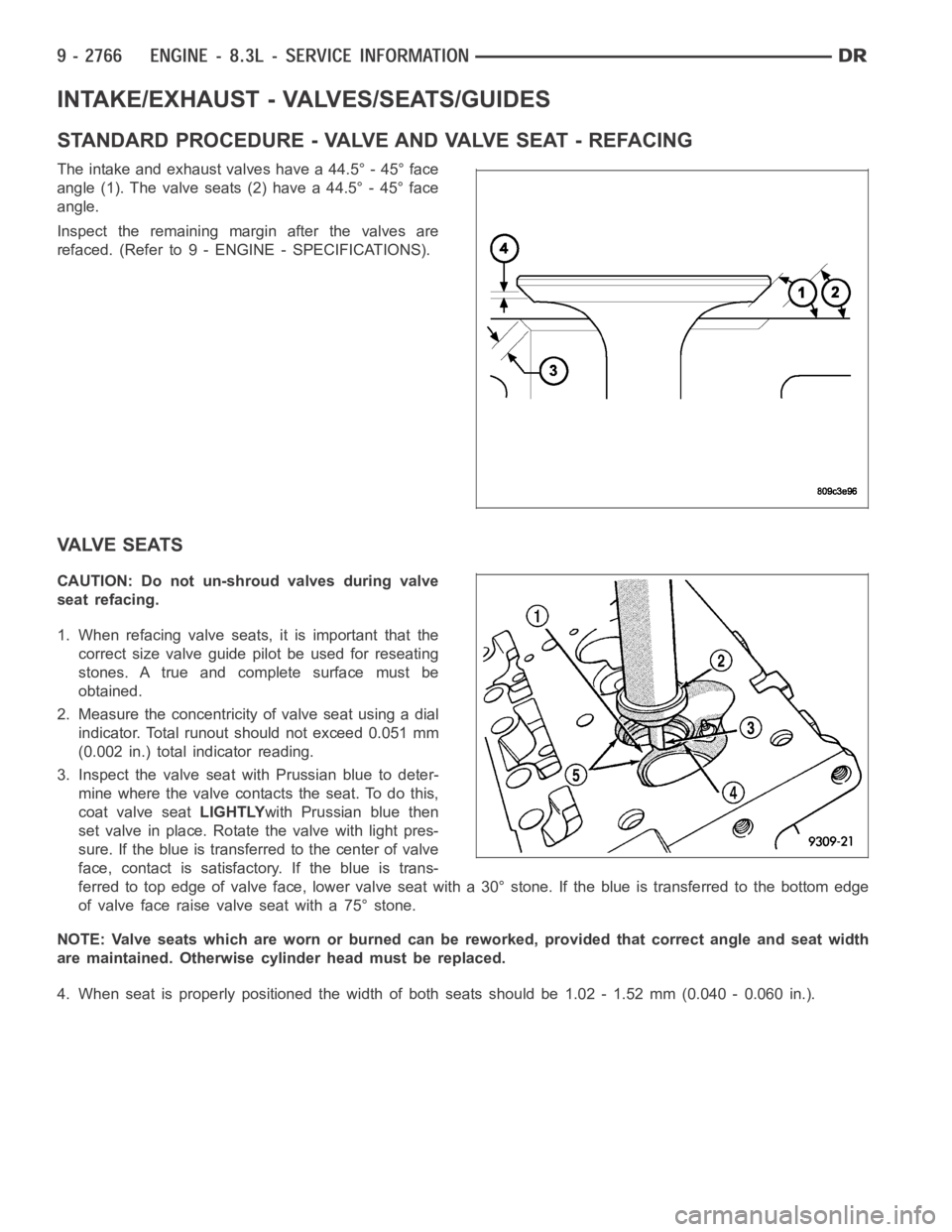
The intake and exhaust valves have a 44.5° - 45° face
angle (1). The valve seats (2) have a 44.5° - 45° face
angle.
Inspect the remaining margin after the valves are
refaced. (Refer to 9 - ENGINE - SPECIFICATIONS).
VALVE SEATS
CAUTION: Do not un-shroud valves during valve
seat refacing.
1. When refacing valve seats, it is important that the
correct size valve guide pilot be used for reseating
stones. A true and complete surface must be
obtained.
2. Measure the concentricity of valve seat using a dial
indicator. Total runout should not exceed 0.051 mm
(0.002 in.) total indicator reading.
3. Inspect the valve seat with Prussian blue to deter-
mine where the valve contacts the seat. To do this,
coat valve seatLIGHTLYwith Prussian blue then
set valve in place. Rotate the valve with light pres-
sure. If the blue is transferred to the center of valve
face, contact is satisfactory. If the blue is trans-
ferred to top edge of valve face, lower valve seat with a 30° stone. If the blue is transferred to the bottom edge
of valve face raise valve seat with a 75° stone.
NOTE: Valve seats which are worn or burned can be reworked, provided that correct angle and seat width
are maintained. Otherwise cylinder head must be replaced.
4. When seat is properly positioned the width of both seats should be 1.02 - 1.52 mm (0.040 - 0.060 in.).