Page 5222 of 5267
5.7L V-8
The 5.7L V-8 engine is equipped with a closed crank-
case ventilation system and a Positive Crankcase
Ventilation (PCV) valve (4).
This system consists of:
a PCV valve mounted into the top of the intake
manifold, located to the right / rear of the throttle
body. The PCV valve (1) is sealed to the intake
manifold with 2 o-rings (2).
passages in the intake manifold.
tubes and hoses to connect the system
components.
Page 5223 of 5267

OPERATION
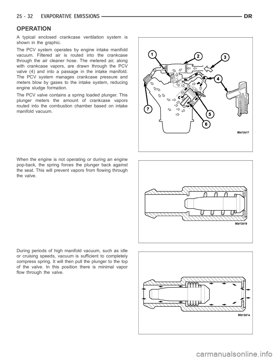
A typical enclosed crankcase ventilation system is
shown in the graphic.
The PCV system operates by engine intake manifold
vacuum. Filtered air is routed into the crankcase
through the air cleaner hose. The metered air, along
with crankcase vapors, are drawn through the PCV
valve (4) and into a passage in the intake manifold.
The PCV system manages crankcase pressure and
meters blow by gases to the intake system, reducing
engine sludge formation.
The PCV valve contains a spring loaded plunger. This
plunger meters the amount of crankcase vapors
routed into the combustion chamber based on intake
manifold vacuum.
When the engine is not operating or during an engine
pop-back, the spring forces the plunger back against
the seat. This will prevent vapors from flowing through
the valve.
During periods of high manifold vacuum, such as idle
or cruising speeds, vacuum is sufficient to completely
compress spring. It will then pull the plunger to the top
of the valve. In this position there is minimal vapor
flow through the valve.
Page 5224 of 5267

During periods of moderate manifold vacuum, the
plunger is only pulled part way back from inlet. This
results in maximum vapor flow through the valve.
DIAGNOSIS AND TESTING
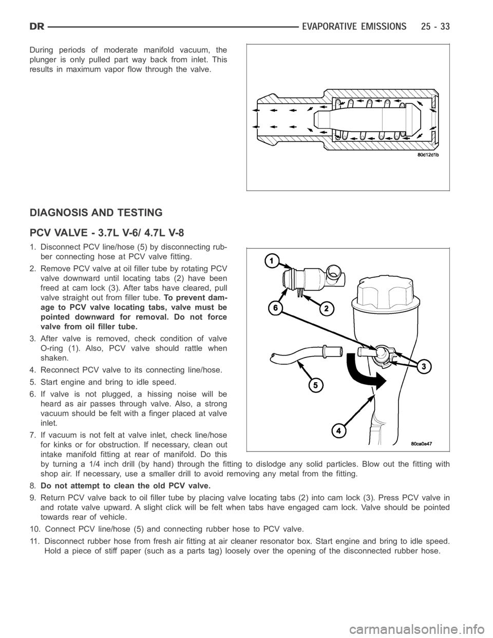
PCVVALVE-3.7LV-6/4.7LV-8
1. Disconnect PCV line/hose (5) by disconnecting rub-
ber connecting hose at PCV valve fitting.
2. Remove PCV valve at oil filler tube by rotating PCV
valve downward until locating tabs (2) have been
freed at cam lock (3). After tabs have cleared, pull
valve straight out from filler tube.To prevent dam-
age to PCV valve locating tabs, valve must be
pointed downward for removal. Do not force
valve from oil filler tube.
3. After valve is removed, check condition of valve
O-ring (1). Also, PCV valve should rattle when
shaken.
4. Reconnect PCV valve to its connecting line/hose.
5. Start engine and bring to idle speed.
6. If valve is not plugged, a hissing noise will be
heard as air passes through valve. Also, a strong
vacuum should be felt with a finger placed at valve
inlet.
7. If vacuum is not felt at valve inlet, check line/hose
for kinks or for obstruction. If necessary, clean out
intake manifold fitting at rear of manifold. Do this
byturninga1/4inchdrill(byhand)throughthefittingtodislodgeanysolid particles. Blow out the fitting with
shop air. If necessary, use a smaller drill to avoid removing any metal fromthe fitting.
8.Do not attempt to clean the old PCV valve.
9. Return PCV valve back to oil filler tube by placing valve locating tabs (2) into cam lock (3). Press PCV valve in
and rotate valve upward. A slight click will be felt when tabs have engaged cam lock. Valve should be pointed
towards rear of vehicle.
10. Connect PCV line/hose (5) and connecting rubber hose to PCV valve.
11. Disconnect rubber hose from fresh air fitting at air cleaner resonatorbox. Start engine and bring to idle speed.
Hold a piece of stiff paper (such as a parts tag) loosely over the opening of the disconnected rubber hose.
Page 5227 of 5267

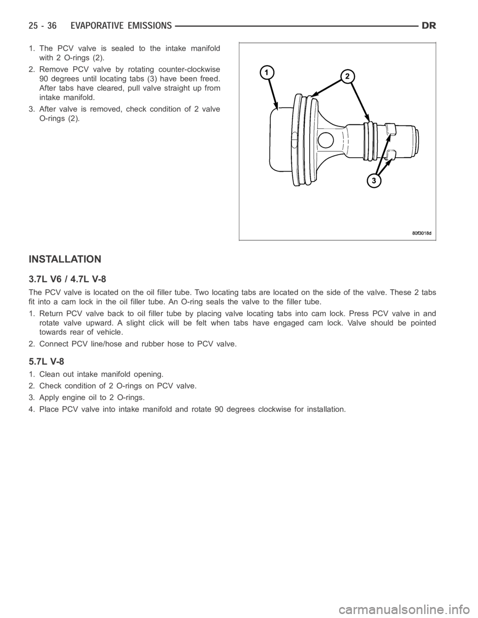
1. The PCV valve is sealed to the intake manifold
with 2 O-rings (2).
2. Remove PCV valve by rotating counter-clockwise
90 degrees until locating tabs (3) have been freed.
After tabs have cleared, pull valve straight up from
intake manifold.
3. After valve is removed, check condition of 2 valve
O-rings (2).
INSTALLATION
3.7L V6 / 4.7L V-8
The PCV valve is located on the oil filler tube. Two locating tabs are locatedonthesideofthevalve.These2tabs
fit into a cam lock in the oil filler tube.An O-ring seals the valve to the filler tube.
1. Return PCV valve back to oil filler tube by placing valve locating tabs into cam lock. Press PCV valve in and
rotate valve upward. A slight click will be felt when tabs have engaged cam lock. Valve should be pointed
towards rear of vehicle.
2. Connect PCV line/hose and rubber hose to PCV valve.
5.7L V-8
1. Clean out intake manifold opening.
2. Check condition of 2 O-rings on PCV valve.
3. Apply engine oil to 2 O-rings.
4. Place PCV valve into intake manifold and rotate 90 degrees clockwise forinstallation.
Page 5231 of 5267
OPERATION
Two EVAP canisters are used. Depending on vehicle model and fuel tank size,the canisters may be mounted either
vertically or horizontally.
The EVAP canisters are filled with granules of an activated carbon mixture. Fuel vapors entering the EVAP canisters
are absorbed by the charcoal granules.
Fuel tank pressure vents into the EVAP canisters. Fuel vapors are temporarily held in the canisters until they can be
drawn into the intake manifold. The duty cycle EVAP canister purge solenoid allows the EVAP canisters to be
purged at predetermined times and at certain engine operating conditions.
REMOVAL
Page 5243 of 5267

VALVE-EGR
DESCRIPTION
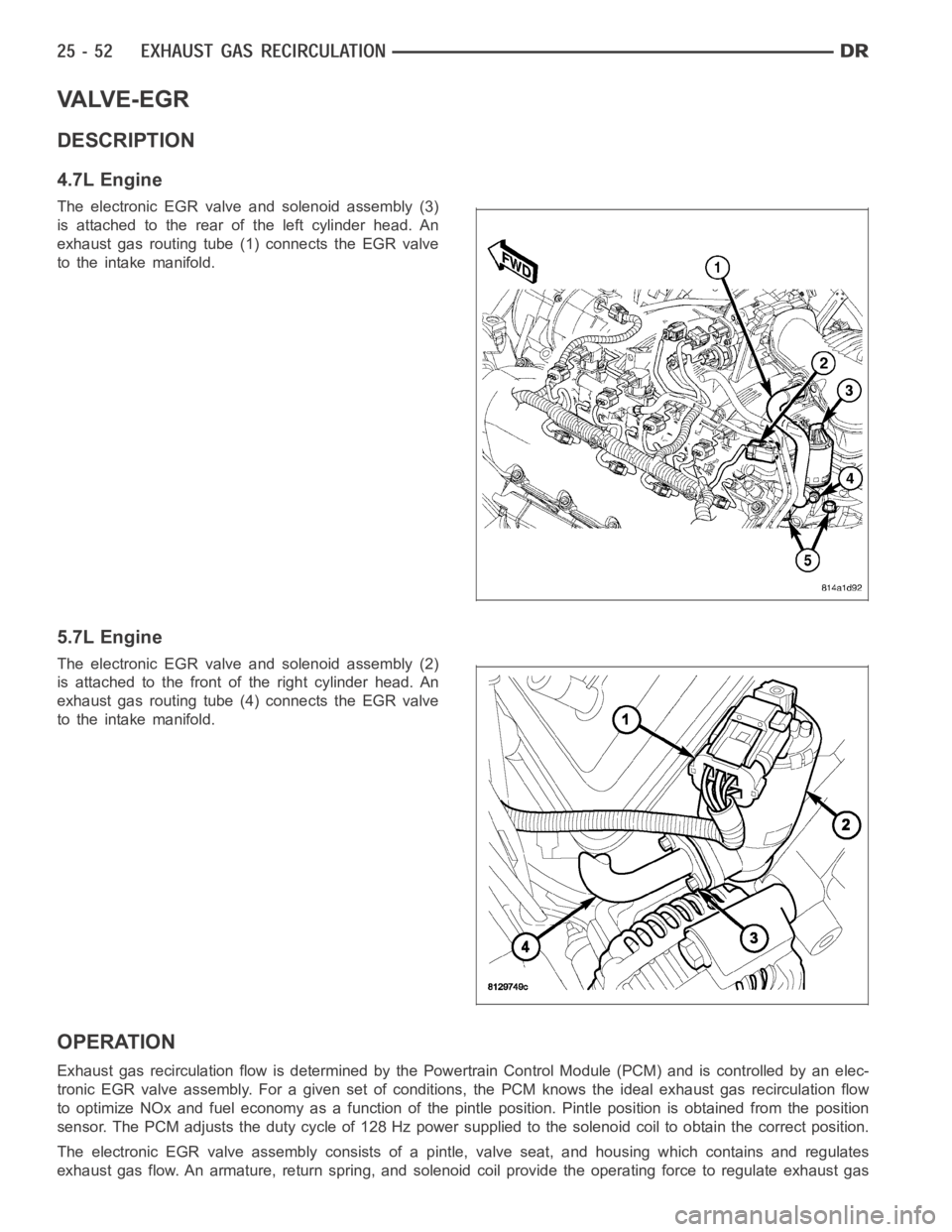
4.7L Engine
The electronic EGR valve and solenoid assembly (3)
is attached to the rear of the left cylinder head. An
exhaust gas routing tube (1) connects the EGR valve
to the intake manifold.
5.7L Engine
The electronic EGR valve and solenoid assembly (2)
is attached to the front of the right cylinder head. An
exhaust gas routing tube (4) connects the EGR valve
to the intake manifold.
OPERATION
Exhaust gas recirculation flow is determined by the Powertrain Control Module (PCM) and is controlled by an elec-
tronic EGR valve assembly. For a given set of conditions, the PCM knows the ideal exhaust gas recirculation flow
to optimize NOx and fuel economy as a function of the pintle position. Pintle position is obtained from the position
sensor. The PCM adjusts the duty cycle of 128 Hz power supplied to the solenoid coil to obtain the correct position.
The electronic EGR valve assembly consists of a pintle, valve seat, and housing which contains and regulates
exhaust gas flow. An armature, return spring, and solenoid coil provide the operating force to regulate exhaust gas
Page 5244 of 5267
flow by changing the pintle position. The solenoid coil assembly is wired in parallel with a diode that connects two
internal connectors.
REMOVAL
4.7L
The electronic EGR valve and solenoid assembly (4)
is attached to the rear of the left cylinder head. An
exhaust gas routing tube (3) connects the EGR valve
to the intake manifold.
1. Remove electrical connector (5) at top of EGR
valve solenoid.
2. Remove tube mounting bolt (1) at intake manifold.
3. Remove two bolts (4) connecting EGR tube (1) to
valve assembly.
4. Remove gasket located between EGR tube flange
and EGR valve assembly.
5. Remove two EGR valve mounting bolts (5).
6. Separate valve assembly (3) from engine.
7. Remove and discard metal gasket located between
cylinder head and valve assembly.