Page 2035 of 5267
31. Disconnect A/C lines and electrical connector from
A/C compressor. Plug holes in A/C compressor to
prevent debris from entering A/C compressor.
32. Disconnect brake booster vacuum hose and fuel
line to fuel rail.
33. Disconnect the cruise control, accelerator cable
and fuel vapor purge harness (2) , then set aside.
34. Disconnect the engine harness connectors on top
of the intake manifold.
35. Disconnect the spark plug wires from the spark
plugs and set the plug wires on top of the engine.
36. Disconnect the ground strap at the thermostat
housing and pull the electrical harness under-
neath the intake manifold and set aside.
Page 2036 of 5267
37. Install Special Tool 9363 - Engine Lifting Brackets
(1) and to the exhaust manifold heat shield studs
where indicated.
38. Insert engine lifting bar (1) through the access
holes in the engine lifting brackets (2) and secure
with the bar retaining pins (3).
Page 2037 of 5267
39. Remove engine with an engine hoist (1).
INSTALLATION - ENGINE ASSEMBLY
1. Attach engine hoist (1) and lower the engine into
engine compartment, aligning the left and right
engine mounts
2. Install left and right engine mount insulator bolts
and nuts. Tighten nuts to 102 Nꞏm (75 ft. lbs.).
3. Remove engine hoist and engine lifting bar (2) and
brackets (3).
Page 2038 of 5267

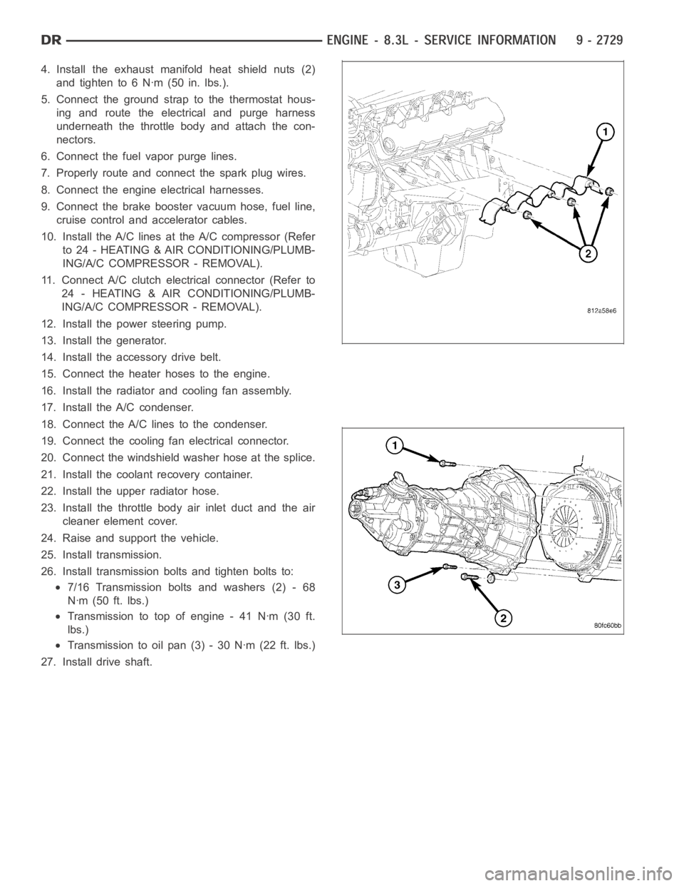
4. Install the exhaust manifold heat shield nuts (2)
and tighten to 6 Nꞏm (50 in. lbs.).
5. Connect the ground strap to the thermostat hous-
ing and route the electrical and purge harness
underneath the throttle body and attach the con-
nectors.
6. Connect the fuel vapor purge lines.
7. Properly route and connect the spark plug wires.
8. Connect the engine electrical harnesses.
9. Connect the brake booster vacuum hose, fuel line,
cruise control and accelerator cables.
10. Install the A/C lines at the A/C compressor (Refer
to 24 - HEATING & AIR CONDITIONING/PLUMB-
ING/A/C COMPRESSOR - REMOVAL).
11. Connect A/C clutch electrical connector (Refer to
24 - HEATING & AIR CONDITIONING/PLUMB-
ING/A/C COMPRESSOR - REMOVAL).
12. Install the power steering pump.
13. Install the generator.
14. Install the accessory drive belt.
15. Connect the heater hoses to the engine.
16. Install the radiator and cooling fan assembly.
17. Install the A/C condenser.
18. Connect the A/C lines to the condenser.
19. Connect the cooling fan electrical connector.
20. Connect the windshield washer hose at the splice.
21. Install the coolant recovery container.
22. Install the upper radiator hose.
23. Install the throttle body air inlet duct and the air
cleaner element cover.
24. Raise and support the vehicle.
25. Install transmission.
26. Install transmission bolts and tighten bolts to:
7/16 Transmission bolts and washers (2) - 68
Nꞏm (50 ft. lbs.)
Transmission to top of engine - 41 Nꞏm (30 ft.
lbs.)
Transmission to oil pan (3) - 30 Nꞏm (22 ft. lbs.)
27. Install drive shaft.
Page 2040 of 5267

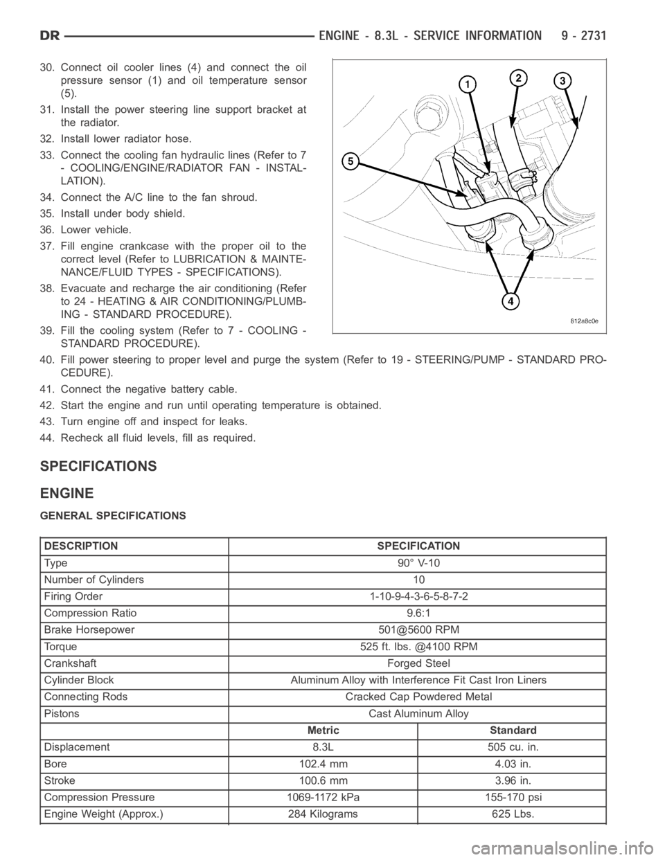
30. Connect oil cooler lines (4) and connect the oil
pressure sensor (1) and oil temperature sensor
(5).
31. Install the power steering line support bracket at
the radiator.
32. Install lower radiator hose.
33. Connect the cooling fan hydraulic lines (Refer to 7
- COOLING/ENGINE/RADIATOR FAN - INSTAL-
LATION).
34. Connect the A/C line to the fan shroud.
35. Install under body shield.
36. Lower vehicle.
37. Fill engine crankcase with the proper oil to the
correct level (Refer to LUBRICATION & MAINTE-
NANCE/FLUID TYPES - SPECIFICATIONS).
38. Evacuate and recharge the air conditioning (Refer
to 24 - HEATING & AIR CONDITIONING/PLUMB-
ING - STANDARD PROCEDURE).
39. Fill the cooling system (Refer to 7 - COOLING -
STANDARD PROCEDURE).
40. Fill power steering to proper leveland purge the system (Refer to 19 - STEERING/PUMP - STANDARD PRO-
CEDURE).
41. Connect the negative battery cable.
42. Start the engine and run until operating temperature is obtained.
43. Turn engine off and inspect for leaks.
44. Recheck all fluid levels, fill as required.
SPECIFICATIONS
ENGINE
GENERAL SPECIFICATIONS
DESCRIPTION SPECIFICATION
Ty pe 9 0° V-1 0
Number of Cylinders 10
Firing Order 1-10-9-4-3-6-5-8-7-2
Compression Ratio 9.6:1
Brake Horsepower 501@5600 RPM
Torque 525 ft. lbs. @4100 RPM
Crankshaft Forged Steel
Cylinder Block Aluminum Alloy with Interference Fit Cast Iron Liners
Connecting Rods Cracked Cap Powdered Metal
Pistons Cast Aluminum Alloy
Metric Standard
Displacement 8.3L 505 cu. in.
Bore 102.4 mm 4.03 in.
Stroke 100.6 mm 3.96 in.
Compression Pressure 1069-1172 kPa 155-170 psi
Engine Weight (Approx.) 284 Kilograms 625 Lbs.
Page 2044 of 5267

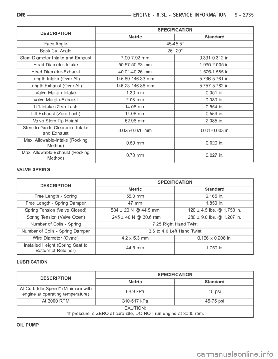
DESCRIPTIONSPECIFICATION
Metric Standard
Face Angle 45-45.5°
Back Cut Angle 25°-29°
Stem Diameter-Intake and Exhaust 7.90-7.92 mm 0.331-0.312 in.
Head Diameter-Intake 50.67-50.93 mm 1.995-2.005 in.
Head Diameter-Exhaust 40.01-40.26 mm 1.575-1.585 in.
Length-Intake (Over All) 145.69-146.33 mm 5.736-5.761 in.
Length-Exhaust (Over All) 146.23-146.86 mm 5.757-5.782 in.
Valve Margin-Intake 1.30 mm 0.051 in.
Valve Margin-Exhaust 2.03 mm 0.080 in.
Lift-Intake (Zero Lash 14.06 mm 0.554 in.
Lift-Exhaust (Zero Lash) 14.06 mm 0.554 in.
Valve Stem Tip Height 52.96 mm 2.085 in.
Stem-to-Guide Clearance-Intake
and Exhaust0.025-0.076 mm 0.001-0.003 in.
Max. Allowable-Intake (Rocking
Method)0.50 mm 0.020 in.
Max. Allowable-Exhaust (Rocking
Method)0.70 mm 0.027 in.
VALVE SPRING
DESCRIPTIONSPECIFICATION
Metric Standard
Free Length - Spring 55.0 mm 2.165 in.
Free Length - Spring Damper 47 mm 1.850 in.
Spring Tension (Valve Closed) 534 ± 20 N @ 44.5 mm 120 ± 4.5 lbs. @ 1.750 in.
Spring Tension (Valve Open) 1245 ± 40 N @ 30.6 mm 280 ± 9.0 lbs. @ 1.207 in.
Number of Coils - Spring 7.25 Right Hand Twist
Number of Coils - Spring Damper 3.6 to 4.0 Left Hand Twist
Wire Diameter (Ovate) 4.2 x 5.3 mm 0.166 x 0.208 in.
Installed Height (Spring Seat to
Bottom of Retainer)44.5 mm 1.750 in.
LUBRICATION
DESCRIPTIONSPECIFICATION
Metric Standard
At Curb Idle Speed* (Minimum with
engine at operating temperature)68.9 kPa 10 psi
At 3000 RPM 310-517 kPa 45-75 psi
CAUTION:
*If pressure is ZERO at curb idle, DO NOT run engine at 3000 rpm.
OIL PUMP
Page 2045 of 5267

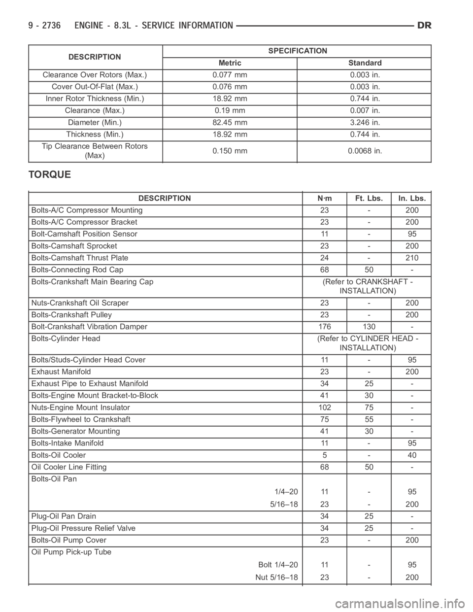
DESCRIPTIONSPECIFICATION
Metric Standard
Clearance Over Rotors (Max.) 0.077 mm 0.003 in.
Cover Out-Of-Flat (Max.) 0.076 mm 0.003 in.
Inner Rotor Thickness (Min.) 18.92 mm 0.744 in.
Clearance (Max.) 0.19 mm 0.007 in.
Diameter (Min.) 82.45 mm 3.246 in.
Thickness (Min.) 18.92 mm 0.744 in.
Tip Clearance Between Rotors
(Max)0.150 mm 0.0068 in.
TORQUE
DESCRIPTION Nꞏm Ft. Lbs. In. Lbs.
Bolts-A/C Compressor Mounting 23 - 200
Bolts-A/C Compressor Bracket 23 - 200
Bolt-Camshaft Position Sensor 11 - 95
Bolts-Camshaft Sprocket 23 - 200
Bolts-Camshaft Thrust Plate 24 - 210
Bolts-Connecting Rod Cap 68 50 -
Bolts-Crankshaft Main Bearing Cap (Refer to CRANKSHAFT -
INSTALLATION)
Nuts-Crankshaft Oil Scraper 23 - 200
Bolts-Crankshaft Pulley 23 - 200
Bolt-Crankshaft Vibration Damper 176 130 -
Bolts-Cylinder Head (Refer to CYLINDER HEAD -
INSTALLATION)
Bolts/Studs-Cylinder Head Cover 11 - 95
Exhaust Manifold 23 - 200
Exhaust Pipe to Exhaust Manifold 34 25 -
Bolts-Engine Mount Bracket-to-Block 41 30 -
Nuts-Engine Mount Insulator 102 75 -
Bolts-Flywheel to Crankshaft 75 55 -
Bolts-Generator Mounting 41 30 -
Bolts-Intake Manifold 11 - 95
Bolts-Oil Cooler 5 - 40
Oil Cooler Line Fitting 68 50 -
Bolts-Oil Pan
1/4–20 11 - 95
5/16–18 23 - 200
Plug-Oil Pan Drain 34 25 -
Plug-Oil Pressure Relief Valve 34 25 -
Bolts-Oil Pump Cover 23 - 200
Oil Pump Pick-up Tube
Bolt 1/4–20 11 - 95
Nut 5/16–18 23 - 200
Page 2047 of 5267
SPECIAL TOOLS
ENGINE
Crankshaft Insert 8194
Crankshaft Damper/Sprocket Installer 9055
Crankshaft Sprocket Remover 9056
Puller 5048
Bearing/Seal Remover Adapter - 8990
Puller, Slide Hammer C-3752
Crankshaft Pilot Bearing Installer 9058
Driver Handle C-4171