Page 2010 of 5267
3. The back plate on the pump seats against the bot-
tom of the bore in the cylinder block. When the
pump is correctly installed, the flange on the pump
will not touch the cylinder block.
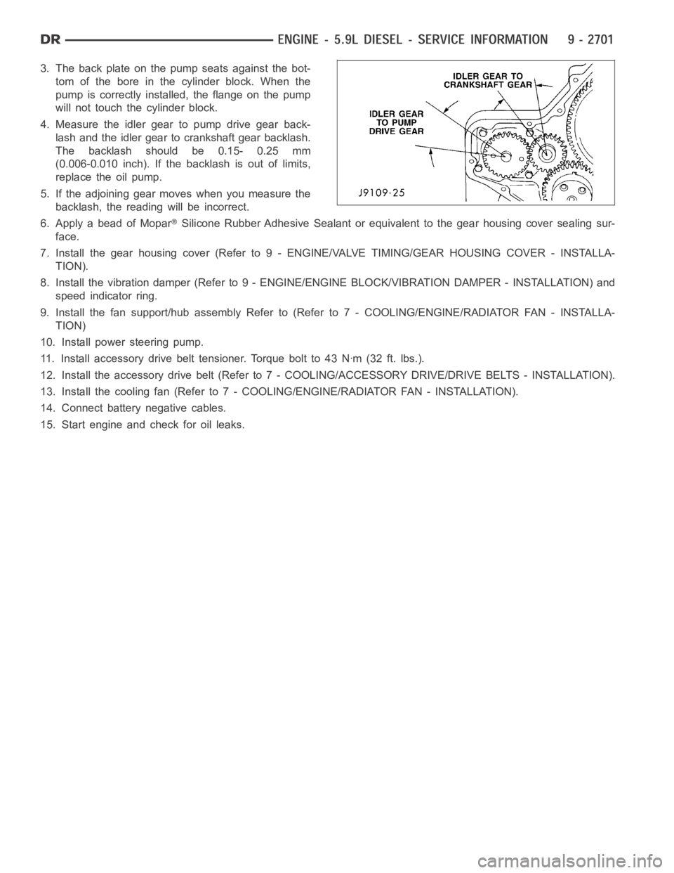
4. Measure the idler gear to pump drive gear back-
lash and the idler gear to crankshaft gear backlash.
The backlash should be 0.15- 0.25 mm
(0.006-0.010 inch). If the backlash is out of limits,
replace the oil pump.
5. If the adjoining gear moves when you measure the
backlash, the reading will be incorrect.
6. Apply a bead of Mopar
Silicone Rubber Adhesive Sealant or equivalent to the gear housing cover sealing sur-
face.
7. Install the gear housing cover (Refer to 9 - ENGINE/VALVE TIMING/GEAR HOUSING COVER - INSTALLA-
TION).
8. Install the vibration damper (Refer to 9 - ENGINE/ENGINE BLOCK/VIBRATION DAMPER - INSTALLATION) and
speed indicator ring.
9. Install the fan support/hub assemblyRefer to (Refer to 7 - COOLING/ENGINE/RADIATOR FAN - INSTALLA-
TION)
10. Install power steering pump.
11. Install accessory drive belt tensioner. Torque bolt to 43 Nꞏm (32 ft. lbs.).
12. Install the accessory drive belt (Refer to 7 - COOLING/ACCESSORY DRIVE/DRIVE BELTS - INSTALLATION).
13. Install the cooling fan (Refer to 7 - COOLING/ENGINE/RADIATOR FAN - INSTALLATION).
14. Connect battery negative cables.
15. Start engine and check for oil leaks.
Page 2011 of 5267
MANIFOLD - INTAKE
REMOVAL
1. Disconnect the battery negative cables.
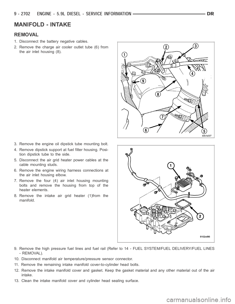
2. Remove the charge air cooler outlet tube (6) from
the air inlet housing (8).
3. Remove the engine oil dipstick tube mounting bolt.
4. Remove dipstick support at fuel filter housing. Posi-
tion dipstick tube to the side.
5. Disconnect the air grid heater power cables at the
cable mounting studs.
6. Remove the engine wiring harness connections at
the air inlet housing elbow.
7. Remove the four (4) air inlet housing mounting
bolts and remove the housing from top of the
heater elements.
8. Remove the intake air grid heater (1)from the
manifold.
9. Remove the high pressure fuel lines and fuel rail (Refer to 14 - FUEL SYSTEM/FUEL DELIVERY/FUEL LINES
- REMOVAL).
10. Disconnect manifold air temperature/pressure sensor connector.
11. Remove the remaining intake manifold cover-to-cylinder head bolts.
12. Remove the intake manifold cover and gasket. Keep the gasket material and any other material out of the air
intake.
13. Clean the intake manifold cover and cylinder head sealing surface.
Page 2012 of 5267
CLEANING
Clean manifold in solvent and blow dry with compressed air.
Clean cylinder block gasket surfaces using a suitable solvent.
The plenum pan rail must be clean and dry (free of all foreign material).
INSPECTION
Inspect manifold for cracks.
Inspect mating surfaces of manifold for flatness with a straightedge.
INSTALLATION
1. Using a new gasket, install the intake manifold cover.
2. Install the cover-to-cylinder head bolts that do not hold down the fuel rail.Tightentheboltsto24Nꞏm(18ft.lbs.)
torque.
3. Install the high pressure rail and fuel lines (Refer to 14 - FUEL SYSTEM/FUEL DELIVERY/FUEL LINES -
INSTALLATION).
4. Using two (2) new gaskets, install the intake air grid heater and air inlet housing.
5. Connect the manifold air temperature/pressure sensor connector.
6. Install and tighten the air intake heater power supply nut to 14 Nꞏm (120 in. lbs.) torque.
7. Install oil dipstick tube support at fuel filter housing.
8. Install the engine oil dipstick tube and mounting bolt.
9. Position the charge air cooler outlet tube onto the air inlet housing. Tightentheclampsto11Nꞏm(100in.lbs.)
torque.
10. Attach the engine wire harness to the air inlet housing.
11. Prime the fuel system. Refer to the fuel priming procedure in Group 14, Fuel System.
12. Connect the battery negative cables.
Page 2014 of 5267
10. Connect the exhaust pipe to the turbocharger and tighten the bolts to 11Nꞏm (100 ft. lbs.) torque.
11. Connect the wastegate command valve connector.
12. Lower the vehicle.
13.Pre-lube the turbocharger.Pour 50 to 60 cc (2 to 3 oz.) clean engine oil in the oil supply line fitting on the
turbo. Rotate the turbocharger impeller by hand to distrubute the oil thoroughly.
14. Install and tighten the oil supply line fitting nut to 24 Nꞏm (18 ft. lbs.) torque.
15. Position the charge air cooler inlet pipe to the turbocharger. With theclamp in position, tighten the clamp nut to
11 Nꞏm (95 in. lbs.) torque.
16. Position the air inlet hose to the turbocharger. Tighten the clamp to 4 Nꞏm (35 in. lbs.) torque.
17. Connect the battery negative cables.
18. Start the engine to check for leaks.
Page 2015 of 5267
VALVE TIMING
STANDARD PROCEDURE - TIMING VERIFICATION
1. Remove the cylinder head cover (Refer to 9 - ENGINE/CYLINDER HEAD/CYLINDER HEAD COVER(S) -
REMOVAL).
2. Remove fuel injector from cylindernumber 1 (Refer to 14 - FUEL SYSTEM/FUEL INJECTION/FUEL INJECTOR
- REMOVAL).
3. Using Special Tool 7471B rotate the engine until the TDC mark on the damper is at 12 o’clock.
4. Using a 8 in.x 1/4 in. dowel rod inserted into cylinder number 1, rock the crankshaft back and forth to verify
piston number 1 is at TDC.
5. With cylinder number still at TDC, inspect the keyway on the crankshaft gear for proper alignment (12 o’clock
position).
6. If the keyway is not at 12 o’clock position replace the crankshaft gear assembly.
7. If the keyway is at 12 o’clock position, remove front gear cover and verify timing mark alignment between the
camshaft gear and crankshaft gear, if not aligned inspect keyway on camshaft gear.
8. Inspect keyway on camshaft gear for proper alignment with the key in the camshaft, if alignment is off replace
the camshaft/gear assembly.
9. If timing marks alignment is off and no damage is found at either the crankshaft or camshaft gear keyways,
realign timing marks as necessary.
Page 2016 of 5267
CASE - FRONT
REMOVAL
1. Disconnect the battery negative cables.
2. Raise vehicle on hoist.
3. Partially drain engine coolant into container suitable for re-use (Refer to 7 - COOLING - STANDARD PROCE-
DURE).
4. Lower vehicle.
5. Remove radiator upper hose.
6. Disconnect coolant recovery bottle hose from radiator filler neck.
7. Remove viscous fan/drive/shroud assembly (Refer to 7 - COOLING/ENGINE/RADIATOR FAN - REMOVAL).
8. Remove the accessory drive belt (Refer to 7 - COOLING/ACCESSORY DRIVE/DRIVE BELTS - REMOVAL).
9. Remove the cooling fan support/hub from the front of the engine.
10. Raisethevehicleonhoist.
11. Remove the crankshaft damper (Refer to 9 - ENGINE/ENGINE BLOCK/VIBRATION DAMPER - REMOVAL) and
speed indicator ring.
12. Remove the lower fan shroud bracket.
13. Remove the upper fan shroud bracket that is mounted to the gear housing.
14. Lower the vehicle.
15. Remove the power steering pump.
16. Remove the accessory drive belt tensioner.
17. Remove the gear cover-to-housing bolts and gently pry the cover away from the housing, taking care not to mar
the gasket surfaces.
18. Remove the fuel injection pump (Refer to 14 - FUEL SYSTEM/FUEL DELIVERY/FUEL INJECTION PUMP -
REMOVAL).
19. Disconnect the camshaft position sensor connector.
20. Disconnect and remove engine speed sensor.
21. Remove the camshaft (Refer to 9 - ENGINE/ENGINE BLOCK/CAMSHAFT & BEARINGS (IN BLOCK) -
REMOVAL).
22. Remove the six front oil pan fasteners.
23. Remove the gear housing fasteners.
NOTE: Use care when removing the gear housing, to avoid damage to the oil pangasket, as the gasket will
be reused if it is not damaged.
24. Slide a feeler gauge between the gear housing and oil pan gasket, to break the gasket seal.
25. Remove the gear housing and gasket.
26. Clean the gasket material from the cylinder block and gear housing.
Page 2017 of 5267
INSTALLATION
1.Inspectoilpangasket.Iftorn,gasketmustbe
replaced.
2. Install a new gear housing gasket onto cylinder
block and trim any excesss gasket material flush to
oil pan rail.
3. Place a small amount of mopar
engine RTV to the
corners of the block and pan gasket T-joint to
ensure a good seal.
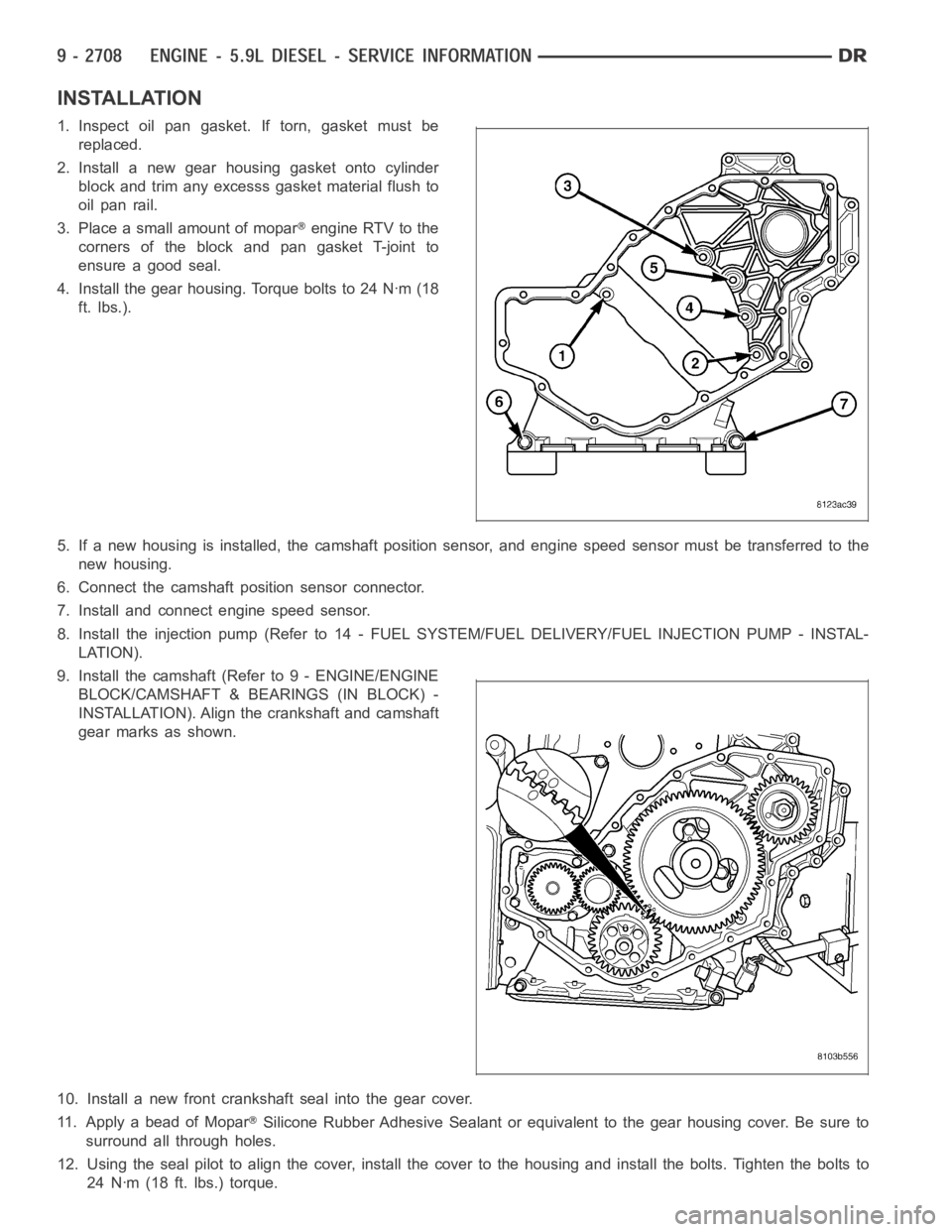
4. Install the gear housing. Torque bolts to 24 Nꞏm (18
ft. lbs.).
5. If a new housing is installed, the camshaft position sensor, and engine speed sensor must be transferred to the
new housing.
6. Connect the camshaft position sensor connector.
7. Install and connect engine speed sensor.
8. Install the injection pump (Refer to 14 - FUEL SYSTEM/FUEL DELIVERY/FUEL INJECTION PUMP - INSTAL-
LATION).
9. Install the camshaft (Refer to 9 - ENGINE/ENGINE
BLOCK/CAMSHAFT & BEARINGS (IN BLOCK) -
INSTALLATION). Align the crankshaft and camshaft
gear marks as shown.
10. Install a new front crankshaft seal into the gear cover.
11. Apply a bead of Mopar
Silicone Rubber Adhesive Sealant or equivalent to the gear housing cover.Be sure to
surround all through holes.
12. Using the seal pilot to align the cover, install the cover to the housingand install the bolts. Tighten the bolts to
24 Nꞏm (18 ft. lbs.) torque.
Page 2018 of 5267
13. Remove the seal pilot. Install front seal dust shield.
14. Raise the vehicle.
15. Install the crankshaft damper and speed indicator ring (Refer to 9 - ENGINE/ENGINE BLOCK/VIBRATION
DAMPER - INSTALLATION). Torque bolts to 40 Nm (30 ft. lbs.), plus an additional 60°.
16. Install the lower fan shroud bracket. Torque bolts to 24 Nꞏm (18 ft. lbs.) torque.
17. Install the upper fan shroud brackets. Hand tighten only.
18. Lower vehicle.
19. Install the fan support/hub assembly and tighten bolts to 32 Nꞏm (24 ft.lbs.) torque.
20. Install the power steering pump.
21. Install the accessory drive belt tensioner. Torque bolt to 43 Nꞏm (32 ft. lbs.) torque.
22. Install the accessory drive belt (Refer to 7 - COOLING/ACCESSORY DRIVE/DRIVE BELTS - INSTALLATION).
23. Install the upper cooling fan/drive/shroud assembly (Refer to 7 - COOLING/ENGINE/RADIATOR FAN - INSTAL-
LATION).
24. Torque the upper fan shroud brackets to 24 Nꞏm (18 ft. lbs.) torque.
25. Connect the coolant recovery bottle hose to the radiator filler neck.
26. Install the radiator upper hose and clamps.
27. Add engine oil.
28. Add coolant (Refer to 7 - COOLING - STANDARD PROCEDURE).
29. Connect the battery cables.
30. Start engine and inspect for leaks.