Page 2048 of 5267
Front Crankshaft Seal Remover C-4679A
Front Crankshaft Seal Installer MD-998306
Rear Crankshaft Seal Installation Guide 9060
Valve Spring Compressor MD998772A
Valve Spring Tester C-647
Pressure Tester Kit 7700
Bloc–Chek–Kit C-3685–A
Clutch Hydraulic Line Disconnect Tool 6638A
Disconnect Tool 9005
ENGINE LIFTING FIXTURE 9363
Page 2055 of 5267
MOUNTS-ENGINE
REMOVAL
NOTE: This procedure covers either the left or
right engine mount.
1. Raise vehicle on hoist.
2. Support oil pan with suitable jack.
3. Loosen engine mount (1) to block bolts or.
4. Loosen engine mount (2) to frame nut
5. Raise engine with jack. Remove engine mount to
block bolts.
6. Remove engine mount or.
Page 2056 of 5267
INSTALLATION
NOTE: This procedure covers either the left or
right engine mount.
1. With engine raised, position engine mount (2) onto
engine and install bolts. Tighten bolts to 41 Nꞏm
(30 ft. lbs.) or.
2. Lower engine with jack while guiding engine mount
(1) studs into frame slots.
3. Install engine mount to frame nut. Tighten nut to
102 Nꞏm (75 ft. lbs.) or.
4. Remove jack.
5. Lower vehicle.
Page 2057 of 5267

MANIFOLD-INTAKE
DIAGNOSIS AND TESTING
INTAKE MANIFOLD LEAKS
An intake manifold air leak is characterized by lower than normal manifoldvacuum, rough idle, or engine misfire.
WARNING: USE EXTREME CAUTION WHEN THE ENGINE IS OPERATING. DO NOT STAND IN ADIRECT LINE
WITH THE FAN. DO NOT PUT YOUR HANDS NEAR THE PULLEYS, BELT OR THE FAN. DO NOT WEAR
LOOSE CLOTHING.
1. Start the engine.
2. Spray a small stream of water (Spray Bottle) at the suspected leak area.
3. If engine RPM’S change, the area of the suspected leak has been found.
4. Repair as required.
REMOVAL
NOTE: Care must be taken to protect the intake
manifold powder coating from scrapes and abra-
sions.
1. Perform the fuel system pressure release proce-
dure,before attempting any repairs.(Refer to 14
- FUEL SYSTEM/FUEL DELIVERY - STANDARD
PROCEDURE - FUEL SYSTEM PRESSURE
RELEASE PROCEDURE).
2. Disconnect negative battery cable.
3. Disconnect throttle body air inlet duct, IAT sensor,
CCV hose and remove air cleaner cover (Refer to
9 - ENGINE/AIR INTAKE SYSTEM - REMOVAL).
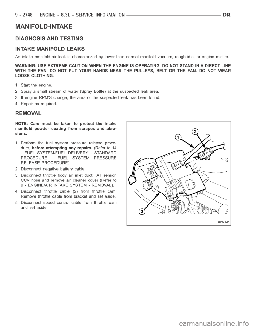
4. Disconnect throttle cable (2) from throttle cam.
Remove throttle cable from bracket and set aside.
5. Disconnect speed control cable from throttle cam
and set aside.
Page 2058 of 5267
6. Disconnect brake booster vacuum hose from the
intake manifold and set aside.
WARNING: WRAP A SHOP TOWEL AROUND FUEL
LINE TO CATCH ANY GASOLINE SPILLAGE.
7. Disconnect fuel line quick connect fitting from fuel
rail (Refer to 14 - FUEL SYSTEM/FUEL DELIV-
ERY/QUICK CONNECT FITTING - STANDARD
PROCEDURE).
8. Disconnect the following electrical connectors:
Left cylinder head fuel injectors
MAP sensor
Engine Coolant Temperature (ECT) Sensor
Idle Speed Control Sensor (ISC)
Throttle Position Sensor (TPS) (1)
Right cylinder head fuel injectors
9. Carefully separate the fuel injector harness push
pins from the intake manifold.
Page 2060 of 5267
INSTALLATION
CAUTION: When cleaning the intake manifold and
cylinder head mating surfaces, do not use a metal
scraper because the surfaces could be cut or
ground. Instead, use a wooden or plastic scraper.
NOTE: Care must be taken to protect the intake
manifold powder coat from possible scrapes and
abrasions.
1. Clean gasket surfaces and remove covering from
intake manifold openings.
2. Carefully install the intake manifold gaskets (2) and
alignment pins (1).
3. Set the intake manifold in position on the engine.
Install intake manifold bolts and tighten initially to 1
Nꞏm (10 in. lbs.). Tighten bolts starting at the center
and working outward to 11 Nꞏm (95 in. lbs.).
4. Connect CCV hoses to left and right cylinder head
covers.
5. Connect fuel line to fuel rail. Pull backward on the
quick connect fitting to ensure complete insertion.
6. Connect the brake booster vacuum hose.
Page 2062 of 5267
10. Reconnect the following electrical connectors:
Left cylinder head fuel injectors
Engine Coolant Temperature (ECT) Sensor
MAP sensor
Idle Speed Control
Throttle Position Sensor
Right cylinder head fuel injectors
11. Install air cleaner cover assembly, connect throttle
body air inlet hose, CCV hose and connect the
Intake Air Temperature Sensor (Refer to 9 -
ENGINE/AIR INTAKE SYSTEM - INSTALLATION).
12. Connect negative battery cable.
13. With the Scan Tool, use the ASD Fuel System
Test to pressurize fuel system to check for leaks.
CAUTION: When using the ASD Fuel System Test,
the Auto Shutdown (ASD) relay will remain ener-
gized for 7 minutes or until the ignition switch is
turned to the OFF position, or Stop All Test is selected.
Page 2066 of 5267

HEAD(S)-CYLINDER
REMOVAL - CYLINDER HEAD(S)
NOTE: Care must be taken to protect the intake
manifold and cylinder head covers powder coating
from scrapes and abrasions. This procedure cov-
ers either the left or right cylinder head.
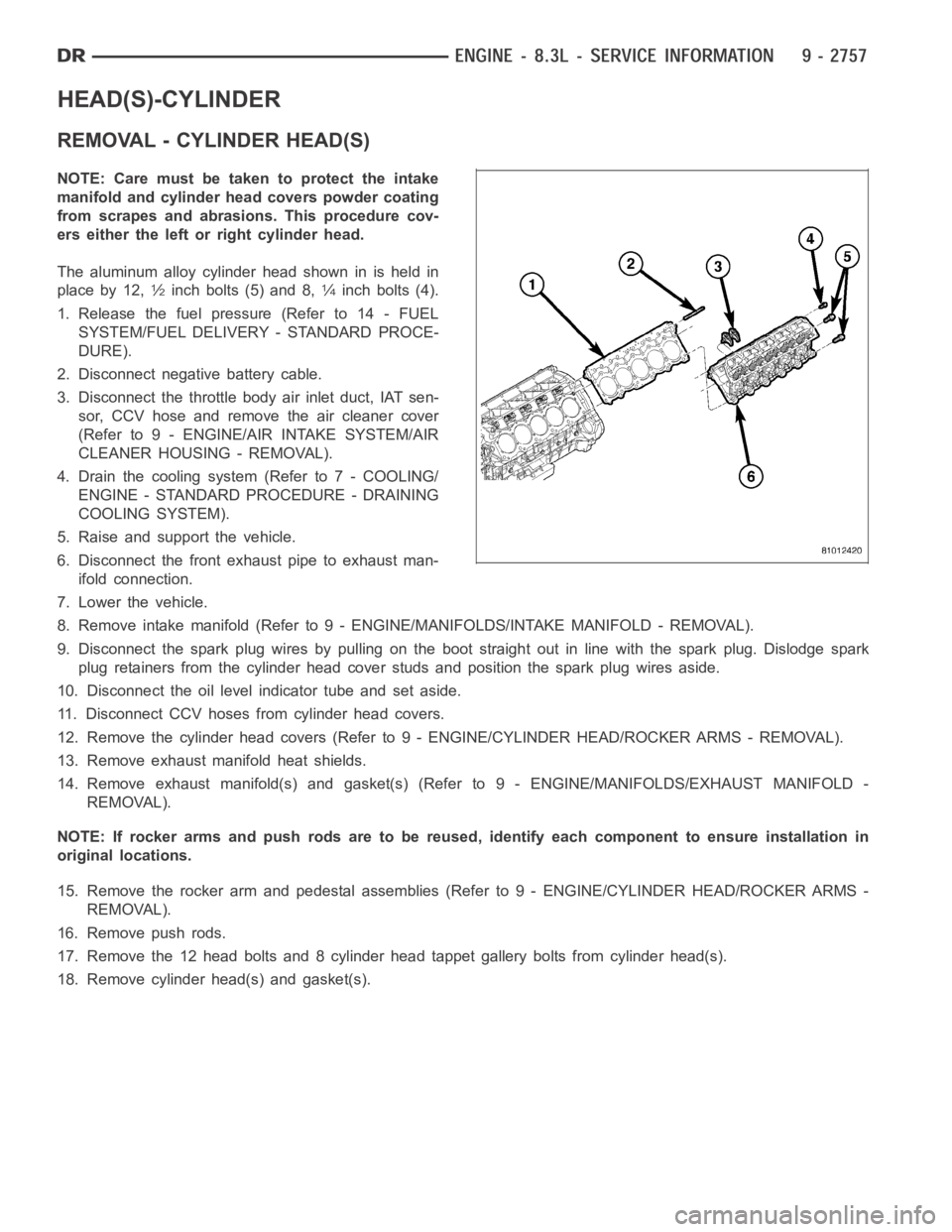
The aluminum alloy cylinder head shown in is held in
place by 12,
1⁄2inch bolts (5) and 8,1⁄4inch bolts (4).
1. Release the fuel pressure (Refer to 14 - FUEL
SYSTEM/FUEL DELIVERY - STANDARD PROCE-
DURE).
2. Disconnect negative battery cable.
3. Disconnect the throttle body air inlet duct, IAT sen-
sor, CCV hose and remove the air cleaner cover
(Refer to 9 - ENGINE/AIR INTAKE SYSTEM/AIR
CLEANER HOUSING - REMOVAL).
4. Drain the cooling system (Refer to 7 - COOLING/
ENGINE - STANDARD PROCEDURE - DRAINING
COOLING SYSTEM).
5. Raise and support the vehicle.
6. Disconnect the front exhaust pipe to exhaust man-
ifold connection.
7. Lower the vehicle.
8. Remove intake manifold (Refer to 9 - ENGINE/MANIFOLDS/INTAKE MANIFOLD-REMOVAL).
9. Disconnect the spark plug wires by pulling on the boot straight out in line with the spark plug. Dislodge spark
plug retainers from the cylinder head cover studs and position the spark plug wires aside.
10. Disconnect the oil level indicator tube and set aside.
11. Disconnect CCV hoses from cylinder head covers.
12. Remove the cylinder head covers (Refer to 9 - ENGINE/CYLINDER HEAD/ROCKER ARMS - REMOVAL).
13. Remove exhaust manifold heat shields.
14. Remove exhaust manifold(s) and gasket(s) (Refer to 9 - ENGINE/MANIFOLDS/EXHAUST MANIFOLD -
REMOVAL).
NOTE: If rocker arms and push rods are to be reused, identify each componentto ensure installation in
original locations.
15. Remove the rocker arm and pedestal assemblies (Refer to 9 - ENGINE/CYLINDER HEAD/ROCKER ARMS -
REMOVAL).
16. Remove push rods.
17. Remove the 12 head bolts and 8 cylinder head tappet gallery bolts from cylinder head(s).
18. Remove cylinder head(s) and gasket(s).