Page 4338 of 5267
BODY
TABLE OF CONTENTS
page page
BODY
WARNING
SAFETY PRECAUTIONS AND WARNINGS ..... 2
DIAGNOSIS AND TESTING
WATER LEAKS .............................. 2
WIND NOISE ................................ 3
STANDARD PROCEDURE
BODY LUBRICATION ......................... 4
HEAT STAKING .............................. 4
BUZZ, SQUEAK & RATTLE ................... 4
PLASTIC BODY PANEL REPAIR ............... 5
SPECIFICATIONS
TORQUE ................................... 14
SPECIAL TOOLS
BODY ...................................... 16TA I L G AT E..............................17
DOOR - FRONT.........................28
DOORS - REAR.........................56
EXTERIOR.............................86
HOOD................................126
INSTRUMENT PANEL....................138
INTERIOR.............................176
PA I N T................................215
SEATS...............................221
STATIONARY GLASS....................256
SUNROOF - SERVICE INFORMATION.......270
WEATHERSTRIP/SEALS..................300
WINCH...............................320
BODY STRUCTURE.....................361
Page 4342 of 5267
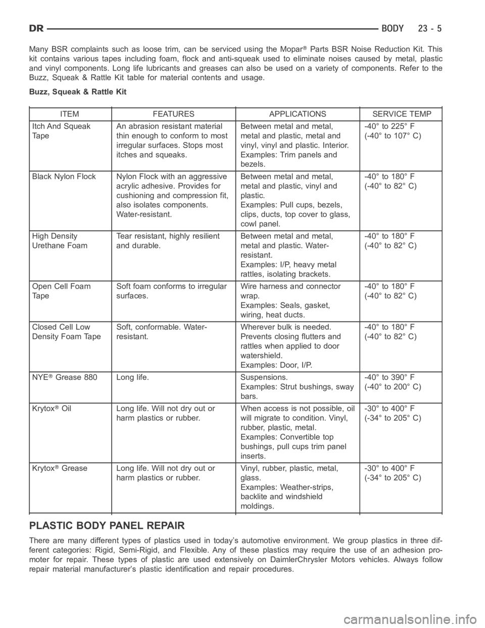
Many BSR complaints such as loose trim, can be serviced using the MoparParts BSR Noise Reduction Kit. This
kit contains various tapes including foam, flock and anti-squeak used to eliminate noises caused by metal, plastic
and vinyl components. Long life lubricants and greases can also be used on avariety of components. Refer to the
Buzz, Squeak & Rattle Kit table for material contents and usage.
Buzz, Squeak & Rattle Kit
ITEM FEATURES APPLICATIONS SERVICE TEMP
Itch And Squeak
TapeAn abrasion resistant material
thin enough to conform to most
irregular surfaces. Stops most
itches and squeaks.Between metal and metal,
metal and plastic, metal and
vinyl, vinyl and plastic. Interior.
Examples: Trim panels and
bezels.-40° to 225° F
(-40° to 107° C)
Black Nylon Flock Nylon Flock with an aggressive
acrylic adhesive. Provides for
cushioning and compression fit,
also isolates components.
Water-resistant.Between metal and metal,
metal and plastic, vinyl and
plastic.
Examples: Pull cups, bezels,
clips, ducts, top cover to glass,
cowl panel.-40° to 180° F
(-40° to 82° C)
High Density
Urethane FoamTear resistant, highly resilient
and durable.Between metal and metal,
metal and plastic. Water-
resistant.
Examples: I/P, heavy metal
rattles, isolating brackets.-40° to 180° F
(-40° to 82° C)
Open Cell Foam
TapeSoft foam conforms to irregular
surfaces.Wire harness and connector
wrap.
Examples: Seals, gasket,
wiring, heat ducts.-40° to 180° F
(-40° to 82° C)
Closed Cell Low
Density Foam TapeSoft, conformable. Water-
resistant.Wherever bulk is needed.
Prevents closing flutters and
rattles when applied to door
watershield.
Examples: Door, I/P.-40° to 180° F
(-40° to 82° C)
NYE
Grease 880 Long life. Suspensions.
Examples: Strut bushings, sway
bars.-40° to 390° F
(-40° to 200° C)
Krytox
Oil Long life. Will not dry out or
harm plastics or rubber.When access is not possible, oil
will migrate to condition. Vinyl,
rubber, plastic, metal.
Examples: Convertible top
bushings, pull cups trim panel
inserts.-30° to 400° F
(-34° to 205° C)
Krytox
Grease Long life. Will not dry out or
harm plastics or rubber.Vinyl, rubber, plastic, metal,
glass.
Examples: Weather-strips,
backlite and windshield
moldings.-30° to 400° F
(-34° to 205° C)
PLASTIC BODY PANEL REPAIR
There are many different types of plastics used in today’s automotive environment. We group plastics in three dif-
ferent categories: Rigid, Semi-Rigid, and Flexible. Any of these plastics may require the use of an adhesion pro-
moter for repair. These types of plastic are used extensively on DaimlerChrysler Motors vehicles. Always follow
repair material manufacturer’s plastic identification and repair procedures.
Page 4359 of 5267
LATCH
REMOVAL
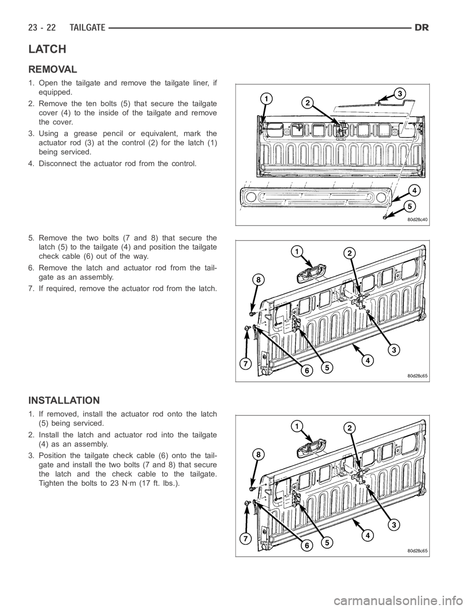
1. Open the tailgate and remove the tailgate liner, if
equipped.
2. Remove the ten bolts (5) that secure the tailgate
cover (4) to the inside of the tailgate and remove
the cover.
3. Using a grease pencil or equivalent, mark the
actuator rod (3) at the control (2) for the latch (1)
being serviced.
4. Disconnect the actuator rod from the control.
5. Remove the two bolts (7 and 8) that secure the
latch (5) to the tailgate (4) and position the tailgate
check cable (6) out of the way.
6. Remove the latch and actuator rod from the tail-
gate as an assembly.
7. If required, remove the actuator rod from the latch.
INSTALLATION
1. If removed, install the actuator rod onto the latch
(5) being serviced.
2. Install the latch and actuator rod into the tailgate
(4) as an assembly.
3. Position the tailgate check cable (6) onto the tail-
gate and install the two bolts (7 and 8) that secure
the latch and the check cable to the tailgate.
Tighten the bolts to 23 Nꞏm (17 ft. lbs.).
Page 4361 of 5267
LATCH STRIKER
REMOVAL
1. Open the tailgate and using a grease pencil or
equivalent, mark the location of the tailgate striker
(1) being serviced.
2. Remove the striker from the cargo box (2).
INSTALLATION
1. Position the striker (1) onto the cargo box (2) using
the reference mark made during the removal pro-
cedure.
2. Tightenthestrikerto34Nꞏm(25ft.lbs.).
Page 4432 of 5267
FRONT FENDER
REMOVAL
1. Remove the radio antenna (Refer to 8 - ELECTRI-
CAL/AUDIO/ANTENNA BODY & CABLE -
REMOVAL).
2. Remove the battery tray (depending on fender
beingserviced)(Referto8-ELECTRICAL/BAT-
TERY SYSTEM/TRAY - REMOVAL).
3. Remove the cowl grille (Refer to 23 - BODY/EXTE-
RIOR/COWL GRILLE - REMOVAL).
4. Remove the headlamp unit (Refer to 8 - ELECTRI-
CAL/LAMPS/LIGHTING - EXTERIOR/HEADLAMP
UNIT - REMOVAL).
5. Remove the wheelhouse splash shield (Refer to 23
- BODY/EXTERIOR/FRONT WHEELHOUSE
SPLASH SHIELD - REMOVAL).
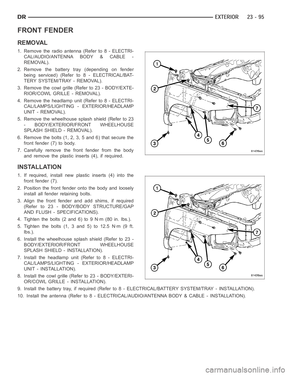
6. Remove the bolts (1, 2, 3, 5 and 6) that secure the
front fender (7) to body.
7. Carefully remove the front fender from the body
and remove the plastic inserts (4), if required.
INSTALLATION
1. If required, install new plastic inserts (4) into the
front fender (7).
2. Position the front fender onto the body and loosely
install all fender retaining bolts.
3. Align the front fender and add shims, if required
(Refer to 23 - BODY/BODY STRUCTURE/GAP
AND FLUSH - SPECIFICATIONS).
4. Tighten the bolts (2 and 6) to 9 Nꞏm (80 in. lbs.).
5. Tighten the bolts (1, 3 and 5) to 12.5 Nꞏm (9 ft.
lbs.).
6. Install the wheelhouse splash shield (Refer to 23 -
BODY/EXTERIOR/FRONT WHEELHOUSE
SPLASH SHIELD - INSTALLATION).
7. Install the headlamp unit (Refer to 8 - ELECTRI-
CAL/LAMPS/LIGHTING - EXTERIOR/HEADLAMP
UNIT - INSTALLATION).
8. Install the cowl grille (Refer to 23 - BODY/EXTERI-
OR/COWL GRILLE - INSTALLATION).
9. Install the battery tray, if required (Refer to 8 - ELECTRICAL/BATTERY SYSTEM/TRAY - INSTALLATION).
10. Install the antenna (Refer to 8 - ELECTRICAL/AUDIO/ANTENNA BODY & CABLE - INSTALLATION).
Page 4446 of 5267
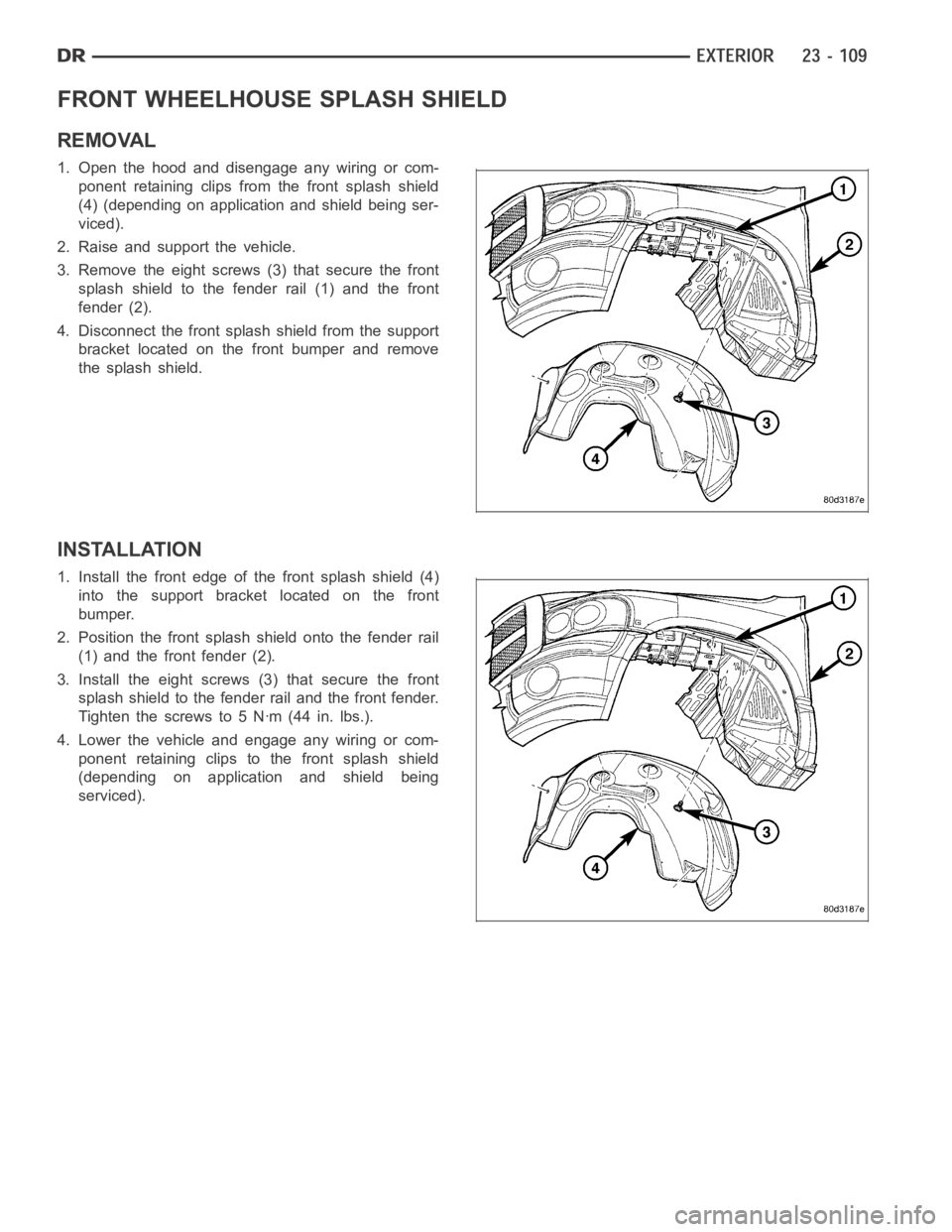
FRONT WHEELHOUSE SPLASH SHIELD
REMOVAL
1. Open the hood and disengage any wiring or com-
ponent retaining clips from the front splash shield
(4) (depending on application and shield being ser-
viced).
2. Raise and support the vehicle.
3. Remove the eight screws (3) that secure the front
splash shield to the fender rail (1) and the front
fender (2).
4. Disconnect the front splash shield from the support
bracket located on the front bumper and remove
the splash shield.
INSTALLATION
1. Install the front edge of the front splash shield (4)
into the support bracket located on the front
bumper.
2. Position the front splash shield onto the fender rail
(1) and the front fender (2).
3. Install the eight screws (3) that secure the front
splash shield to the fender rail and the front fender.
Tighten the screws to 5 Nꞏm (44 in. lbs.).
4. Lower the vehicle and engage any wiring or com-
ponent retaining clips to the front splash shield
(depending on application and shield being
serviced).
Page 4467 of 5267
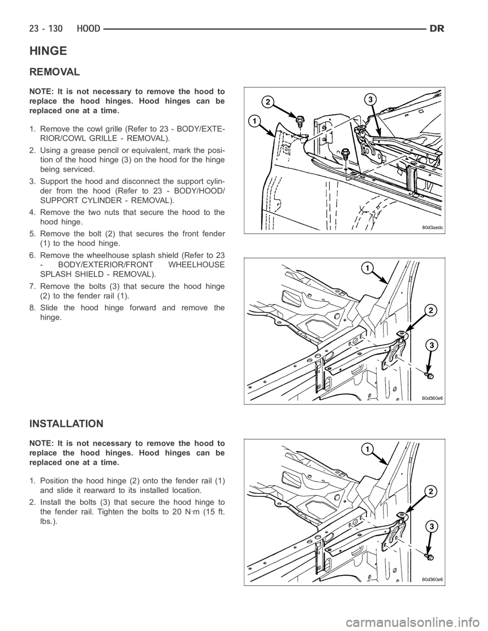
HINGE
REMOVAL
NOTE: It is not necessary to remove the hood to
replace the hood hinges. Hood hinges can be
replaced one at a time.
1. Remove the cowl grille (Refer to 23 - BODY/EXTE-
RIOR/COWL GRILLE - REMOVAL).
2. Using a grease pencil or equivalent, mark the posi-
tion of the hood hinge (3) on the hood for the hinge
being serviced.
3. Support the hood and disconnect the support cylin-
der from the hood (Refer to 23 - BODY/HOOD/
SUPPORT CYLINDER - REMOVAL).
4. Remove the two nuts that secure the hood to the
hood hinge.
5. Remove the bolt (2) that secures the front fender
(1) to the hood hinge.
6. Remove the wheelhouse splash shield (Refer to 23
- BODY/EXTERIOR/FRONT WHEELHOUSE
SPLASH SHIELD - REMOVAL).
7. Remove the bolts (3) that secure the hood hinge
(2) to the fender rail (1).
8. Slide the hood hinge forward and remove the
hinge.
INSTALLATION
NOTE: It is not necessary to remove the hood to
replace the hood hinges. Hood hinges can be
replaced one at a time.
1. Position the hood hinge (2) onto the fender rail (1)
and slide it rearward to its installed location.
2. Install the bolts (3) that secure the hood hinge to
the fender rail. Tighten the bolts to 20 Nꞏm (15 ft.
lbs.).
Page 4476 of 5267
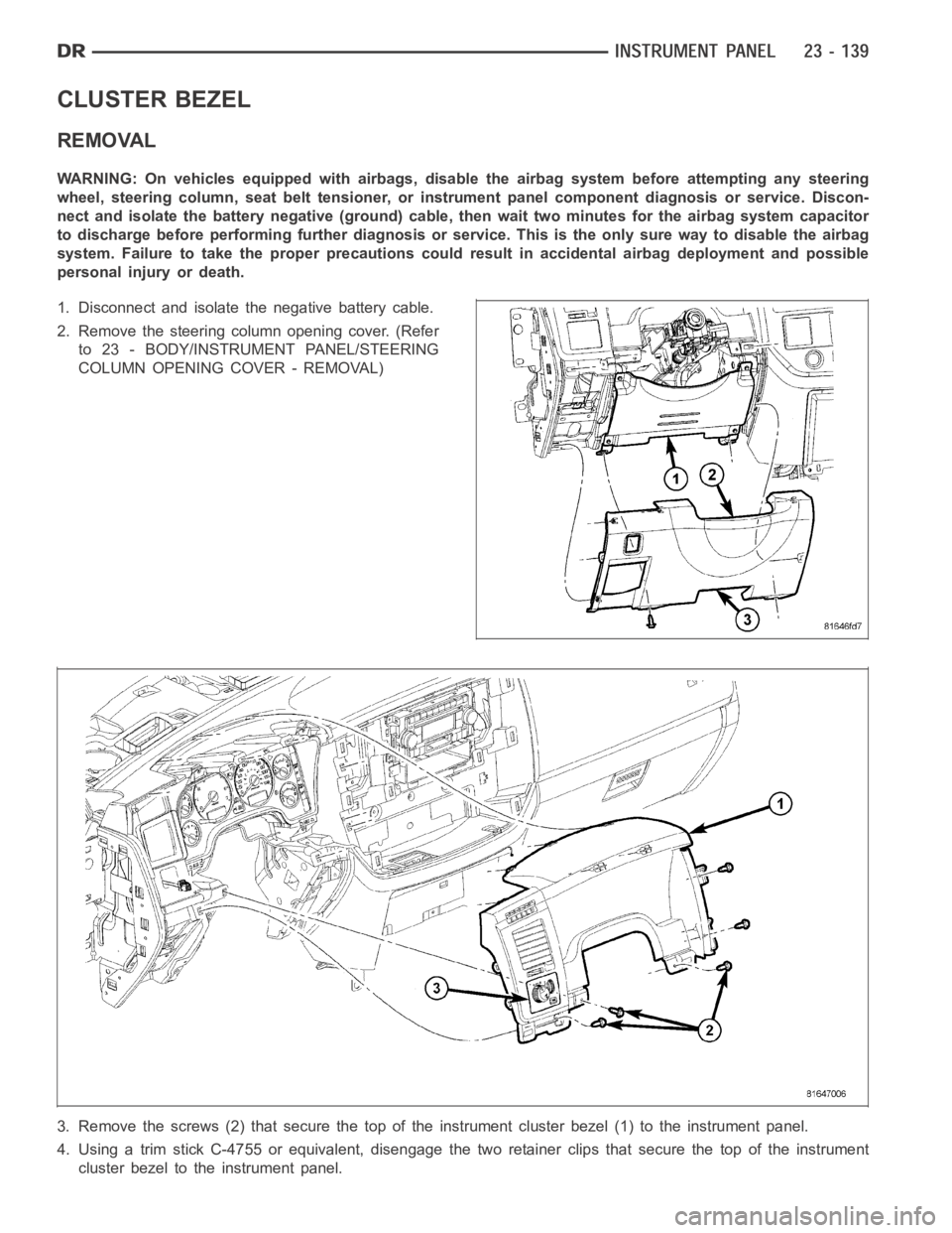
CLUSTER BEZEL
REMOVAL
WARNING: On vehicles equipped with airbags, disable the airbag system before attempting any steering
wheel, steering column, seat belt tensioner, or instrument panel component diagnosis or service. Discon-
nect and isolate the battery negative (ground) cable, then wait two minutes for the airbag system capacitor
to discharge before performing further diagnosis or service. This is the only sure way to disable the airbag
system. Failure to take the proper precautions could result in accidentalairbag deployment and possible
personal injury or death.
1. Disconnect and isolate the negative battery cable.
2. Remove the steering column opening cover. (Refer
to 23 - BODY/INSTRUMENT PANEL/STEERING
COLUMN OPENING COVER - REMOVAL)
3. Remove the screws (2) that secure the top of the instrument cluster bezel(1) to the instrument panel.
4. Using a trim stick C-4755 or equivalent, disengage the two retainer clips that secure the top of the instrument
cluster bezel to the instrument panel.