2006 DODGE RAM SRT-10 service
[x] Cancel search: servicePage 5188 of 5267
OIL-A/C REFRIGERANT
DESCRIPTION
The refrigerant oil used in R-134a refrigerant systems is a synthetic-based, polyalkylene glycol (PAG), wax-free
lubricant. Mineral-based R-12 refrigerant oils are not compatible with PAG oils, and should never be introduced to
an R-134a refrigerant system.
There are different PAG oils available, and each contains a different additive package. Useonlyrefrigerant oil of the
same type as recommended to service the refrigerant system (always refer to the specification tagincluded with
the replacement A/C compressor or the A/C Underhood Specification Label located in the engine compartment).
The Denso 10S17 A/C compressor used in this vehicle when equipped with the 3.7L, 4.7L, 5.7L or 8.3L engine is
designed to use ND-8 PAG refrigerant oil. Use only this type of refrigerantoil when servicing the A/C compressor for
these engines.
The Visteon HS-18 A/C compressor used in this vehicle when equipped with 5.9L diesel engine is designed to use
VC-46 PAG refrigerant oil. Use only this type of refrigerant oil when servicing this A/C compressor.
OPERATION
After performing any refrigerant recovery or recycling operation, always replenish the refrigerant system with the
same amount of the recommended refrigerant oil as was removed. Too little refrigerant oil can cause A/C compres-
sor damage, and too much can reduce A/C system performance.
PAG refrigerant oil is more hygroscopic than mineral oil, and will absorb any moisture it comes into contact with,
even moisture in the air. The PAG oil container should always be kept tightly capped until it is ready to be used.
After use, recap the oil container immediately to prevent moisture contamination.
STANDARD PROCEDURE
REFRIGERANT OIL LEVEL
When an A/C system is assembled at the factory, all components except the A/C compressor are refrigerant oil free.
After the refrigerant system has been charged and operated, the refrigerant oil in the A/C compressor is dispersed
throughout the refrigerant system. The accumulator, A/C evaporator, A/Ccondenser and the A/C compressor will
each retain a significant amount of the needed refrigerant oil.
It is important to have the correct amount of refrigerant oil in the A/C system. This ensures proper lubrication of the
A/C compressor. Too little oil will result in damage to the A/C compressor,while too much oil will reduce the cooling
capacity of the A/C system and consequently result in higher discharge airtemperatures.
CAUTION: The refrigerant oil in the R-134a A/C system is unique depending on the A/C compressor used.
Use only PAG oils that are designed to work with R-134a refrigerant and the A/C compressor in the vehicle.
Always refer to the A/C Underhood Specification Label for the correct oil designation. The oil container
should be kept tightly capped until it is ready for use and then tightly capped after use to prevent contam-
ination from dirt and moisture. Refrigerant oil will quickly absorb any moisture it comes in contact with,
therefore, special effort must be used to keep all R-134a system components moisture-free. Moisture in the
refrigerant oil is very difficult toremove and will cause a reliability problem with the A/C compressor.
NOTE: Most reclaim/recycling equipment will measure the lubricant beingremoved during recovery. This
amount of lubricant should be added back into the system. Refer to the reclaim/recycling equipment man-
ufacturers instructions.
It will not be necessary to check the oil level in the A/C compressor or to addoil, unless there has been an oil loss.
An oil loss may occur due to a rupture or leak from a refrigerant line, a connector fitting, a component, or a com-
ponent seal. If a leak occurs, add 30 milliliters (1 fluid ounce) of refrigerant oil to the refrigerant system after the
repair has been made. Refrigerant oil loss will be evident at the leak pointby the presence of a wet, shiny surface
around the leak.
Refrigerant oil must be added when an accumulator, A/C evaporator or A/C condenser is replaced. See the Refrig-
erant Oil Capacities chart. When an A/C compressor is replaced, the refrigerant oil must be drained from the old
Page 5190 of 5267
REFRIGERANT-A/C
DESCRIPTION
The refrigerant used in this air conditioning system is a HydroFluoroCarbon (HFC), type R-134a. Unlike R-12, which
is a ChloroFluoroCarbon (CFC), R-134a refrigerant does not contain ozone-depleting chlorine. R-134a refrigerant is
a non-toxic, non-flammable, clear, and colorless liquefied gas.
Even though R-134a does not contain chlorine, it must be reclaimed and recycled just like CFC-type refrigerants.
This is because R-134a is a greenhouse gas and can contribute to global warming.
OPERATION
R-134a refrigerant is not compatiblewith R-12 refrigerant in an A/C system. Even a small amount of R-12 refrigerant
added to an R-134a refrigerant system will cause A/C compressor failure, refrigerant oil sludge or poor A/C system
performance. In addition, the polyalkylene glycol (PAG) synthetic refrigerant oils used in an R-134a refrigerant sys-
tem are not compatible with the mineral-based refrigerant oils used in an R-12 refrigerant system.
R-134a refrigerant system service ports, service tool couplers and refrigerant dispensing bottles have all been
designed with unique fittings to ensure that an R-134a refrigerant systemis not accidentally contaminated with the
wrong refrigerant (R-12). There are also labels posted in the engine compartment of the vehicle and on the A/C
compressor to identify that the A/C system is equipped with R-134a refrigerant.
Page 5191 of 5267
TUBE-A/C ORIFICE
DESCRIPTION
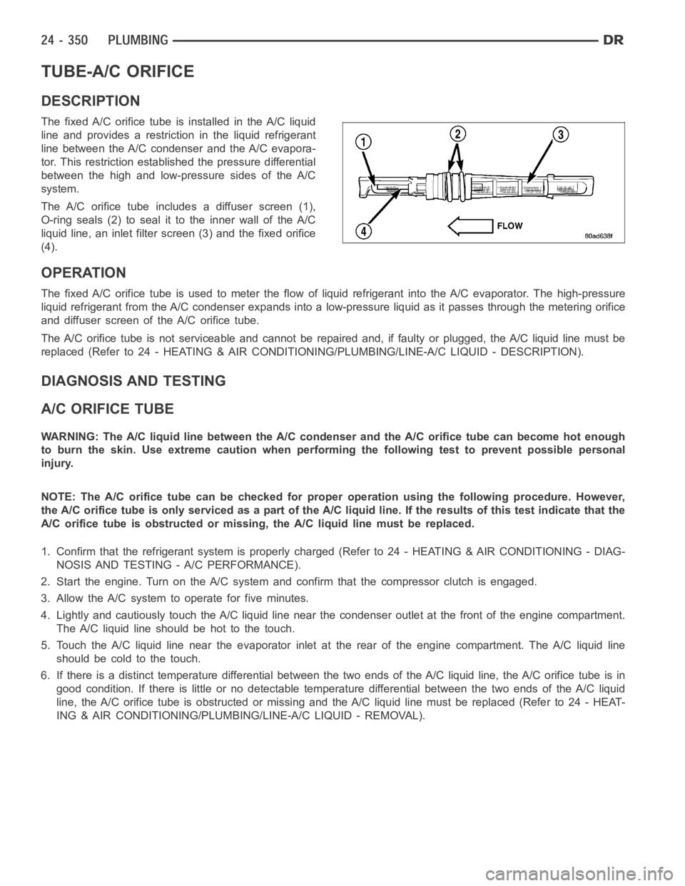
The fixed A/C orifice tube is installed in the A/C liquid
line and provides a restriction in the liquid refrigerant
line between the A/C condenser and the A/C evapora-
tor. This restriction established the pressure differential
between the high and low-pressure sides of the A/C
system.
The A/C orifice tube includes a diffuser screen (1),
O-ring seals (2) to seal it to the inner wall of the A/C
liquid line, an inlet filter screen (3) and the fixed orifice
(4).
OPERATION
The fixed A/C orifice tube is used to meter the flow of liquid refrigerant into the A/C evaporator. The high-pressure
liquid refrigerant from the A/C condenser expands into a low-pressure liquid as it passes through the metering orifice
and diffuser screen of the A/C orifice tube.
The A/C orifice tube is not serviceable and cannot be repaired and, if faulty or plugged, the A/C liquid line must be
replaced (Refer to 24 - HEATING & AIR CONDITIONING/PLUMBING/LINE-A/C LIQUID - DESCRIPTION).
DIAGNOSIS AND TESTING
A/C ORIFICE TUBE
WARNING: The A/C liquid line between the A/C condenser and the A/C orifice tube can become hot enough
to burn the skin. Use extreme caution when performing the following test toprevent possible personal
injury.
NOTE: The A/C orifice tube can be checked for proper operation using the following procedure. However,
the A/C orifice tube is only serviced as a part of the A/C liquid line. If the results of this test indicate that the
A/C orifice tube is obstructed or missing, the A/C liquid line must be replaced.
1. Confirm that the refrigerant system is properly charged (Refer to 24 - HEATING & AIR CONDITIONING - DIAG-
NOSIS AND TESTING - A/C PERFORMANCE).
2. Start the engine. Turn on the A/Csystem and confirm that the compressor clutch is engaged.
3. Allow the A/C system to operate for five minutes.
4. Lightly and cautiously touch the A/C liquid line near the condenser outlet at the front of the engine compartment.
TheA/Cliquidlineshouldbehottothetouch.
5. Touch the A/C liquid line near the evaporator inlet at the rear of the engine compartment. The A/C liquid line
should be cold to the touch.
6. If there is a distinct temperature differential between the two ends of the A/C liquid line, the A/C orifice tube is in
good condition. If there is little or no detectable temperature differential between the two ends of the A/C liquid
line, the A/C orifice tube is obstructed or missing and the A/C liquid line must be replaced (Refer to 24 - HEAT-
ING & AIR CONDITIONING/PLUMBING/LINE-A/C LIQUID - REMOVAL).
Page 5207 of 5267
PUMP-LEAK DETECTION
DESCRIPTION
Vehicles equipped with JTEC engine control modules use a leak detection pump. Vehicles equipped with NGC
engine control modules use an NVLD pump. Refer to Natural Vacuum - Leak Detection (NVLD) for additional infor-
mation.
The evaporative emission system is designed to prevent the escape of fuel vapors from the fuel system. Leaks in
the system, even small ones, can allow fuel vapors to escape into the atmosphere. Government regulations require
onboard testing to make sure that the evaporative (EVAP) system is functioning properly. The leak detection system
tests for EVAP system leaks and blockage. It also performs self-diagnostics. During self-diagnostics, the Powertrain
Control Module (PCM) first checks the Leak Detection Pump (LDP) for electrical and mechanical faults. If the first
checks pass, the PCM then uses the LDP to seal the vent valve and pump air intothe system to pressurize it. If a
leak is present, the PCM will continue pumping the LDP to replace the air that leaks out. The PCM determines the
size of the leak based on how fast/long it must pump the LDP as it tries to maintain pressure in the system.
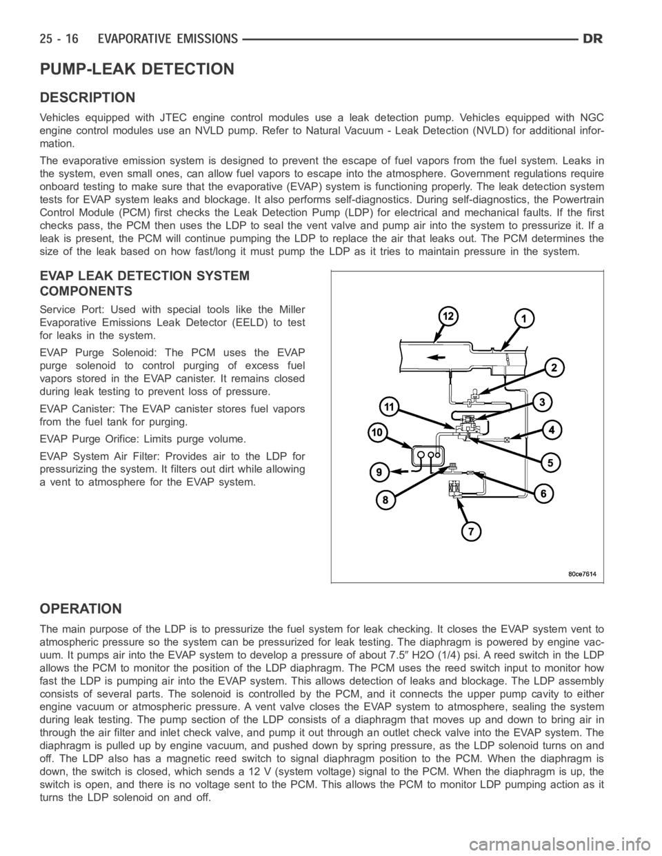
EVAP LEAK DETECTION SYSTEM
COMPONENTS
Service Port: Used with special tools like the Miller
Evaporative Emissions Leak Detector (EELD) to test
for leaks in the system.
EVAP Purge Solenoid: The PCM uses the EVAP
purge solenoid to control purging of excess fuel
vapors stored in the EVAP canister. It remains closed
during leak testing to prevent loss of pressure.
EVAP Canister: The EVAP canister stores fuel vapors
from the fuel tank for purging.
EVAP Purge Orifice: Limits purge volume.
EVAP System Air Filter: Provides air to the LDP for
pressurizing the system. It filters out dirt while allowing
a vent to atmosphere for the EVAP system.
OPERATION
The main purpose of the LDP is to pressurize the fuel system for leak checking. It closes the EVAP system vent to
atmospheric pressure so the system can be pressurized for leak testing. The diaphragm is powered by engine vac-
uum. It pumps air into the EVAP system to develop a pressure of about 7.5
H2O (1/4) psi. A reed switch in the LDP
allows the PCM to monitor the position of the LDP diaphragm. The PCM uses thereed switch input to monitor how
fast the LDP is pumping air into the EVAP system. This allows detection of leaks and blockage. The LDP assembly
consists of several parts. The solenoid is controlled by the PCM, and it connects the upper pump cavity to either
engine vacuum or atmospheric pressure. A vent valve closes the EVAP systemto atmosphere, sealing the system
during leak testing. The pump section of the LDP consists of a diaphragm that moves up and down to bring air in
through the air filter and inlet check valve, and pump it out through an outlet check valve into the EVAP system. The
diaphragm is pulled up by engine vacuum, and pushed down by spring pressure, as the LDP solenoid turns on and
off. The LDP also has a magnetic reed switch to signal diaphragm position tothe PCM. When the diaphragm is
down, the switch is closed, which sends a 12 V (system voltage) signal to thePCM. When the diaphragm is up, the
switch is open, and there is no voltage sent to the PCM. This allows the PCM tomonitor LDP pumping action as it
turns the LDP solenoid on and off.
Page 5210 of 5267
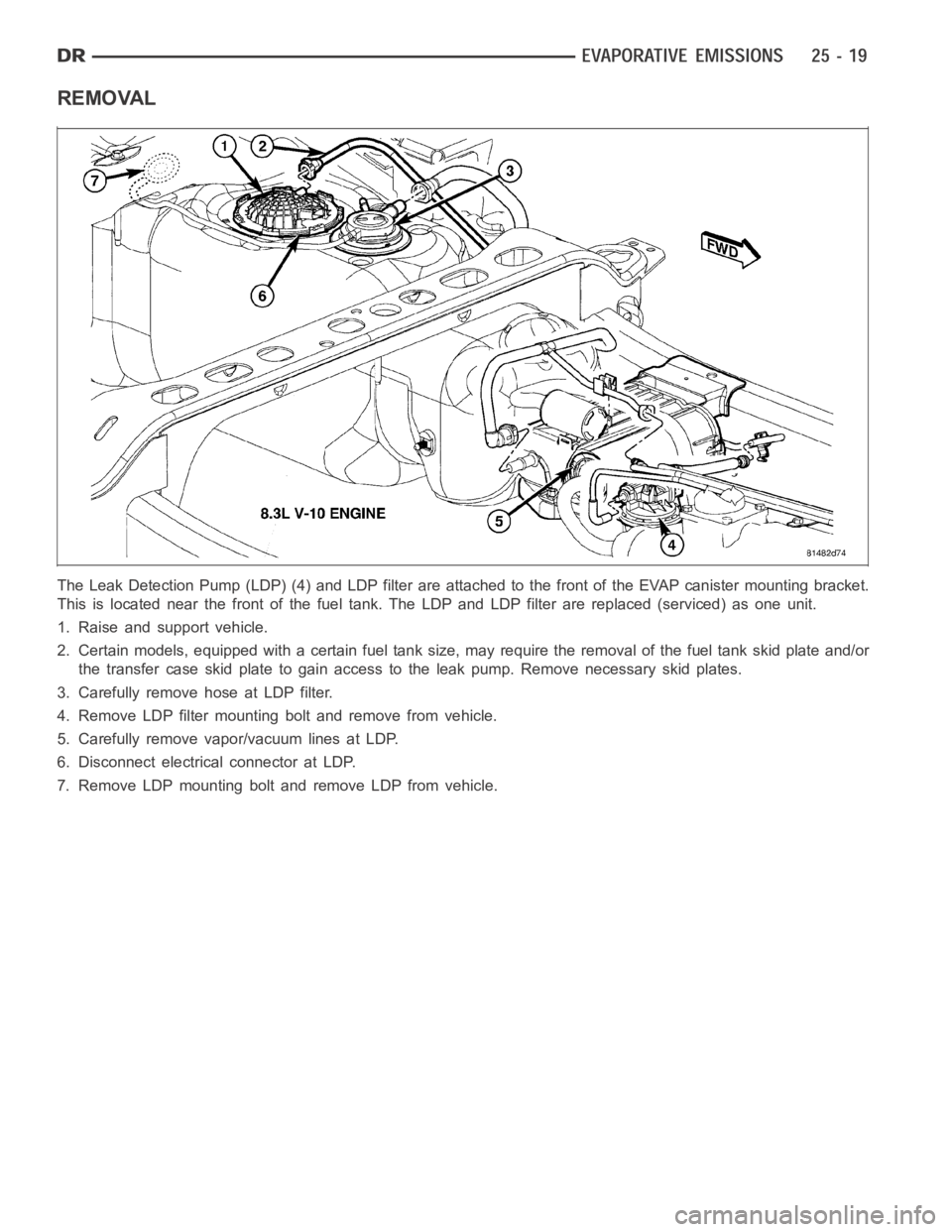
REMOVAL
The Leak Detection Pump (LDP) (4) and LDP filter are attached to the front ofthe EVAP canister mounting bracket.
This is located near the front of the fuel tank. The LDP and LDP filter are replaced (serviced) as one unit.
1. Raise and support vehicle.
2. Certain models, equipped with a certain fuel tank size, may require the removal of the fuel tank skid plate and/or
the transfer case skid plate to gain access to the leak pump. Remove necessary skid plates.
3. Carefully remove hose at LDP filter.
4. Remove LDP filter mounting bolt and remove from vehicle.
5. Carefully remove vapor/vacuum lines at LDP.
6. Disconnect electrical connector at LDP.
7. Remove LDP mounting bolt and remove LDP from vehicle.
Page 5211 of 5267
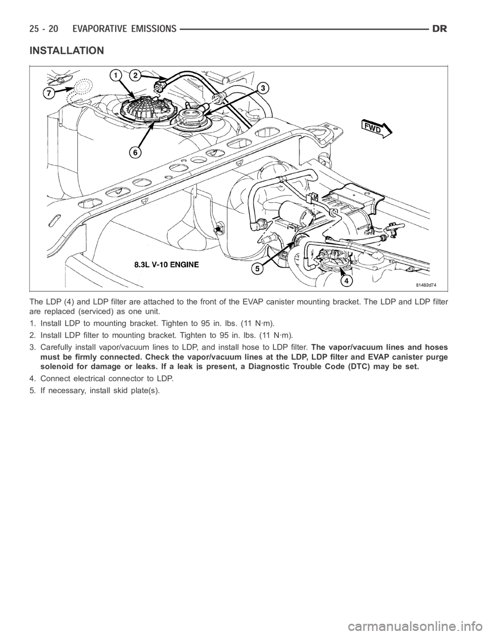
INSTALLATION
The LDP (4) and LDP filter are attached to the front of the EVAP canister mounting bracket. The LDP and LDP filter
are replaced (serviced) as one unit.
1. Install LDP to mounting bracket. Tighten to 95 in. lbs. (11 Nꞏm).
2. Install LDP filter to mounting bracket. Tighten to 95 in. lbs. (11 Nꞏm).
3. Carefully install vapor/vacuum lines to LDP, and install hose to LDP filter.The vapor/vacuum lines and hoses
must be firmly connected. Check the vapor/vacuum lines at the LDP, LDP filter and EVAP canister purge
solenoid for damage or leaks. If a leak is present, a Diagnostic Trouble Code (DTC) may be set.
4. Connect electrical connector to LDP.
5. If necessary, install skid plate(s).
Page 5266 of 5267
SERVICE MANUAL COMMENTS
What errors(s) have you found?
______________________________________________________________________________________
______________________________________________________________________________________
______________________________________________________________________________________
______________________________________________________________________________________
In order for us to assist you, please include as much details as possible when reporting an error
Comments / Suggestions
______________________________________________________________________________________
______________________________________________________________________________________
______________________________________________________________________________________
______________________________________________________________________________________
Dealership Technician
Dealer Code:Retail Customer
M a n u a l Ti t l e , Ye a r, N u m b e r a nd P a g e : _________________________________________________
______________________________________________________________________________________
Yo u r N a m e : ________________________________________________________________________
Address: ________________________________________________________________________
________________________________________________________________________
________________________________________________________________________
All comments become property of DaimlerChrysler and may be used without compensation.