2006 DODGE RAM SRT-10 service
[x] Cancel search: servicePage 5136 of 5267
COMPRESSOR-A/C
DESCRIPTION
A/C COMPRESSOR
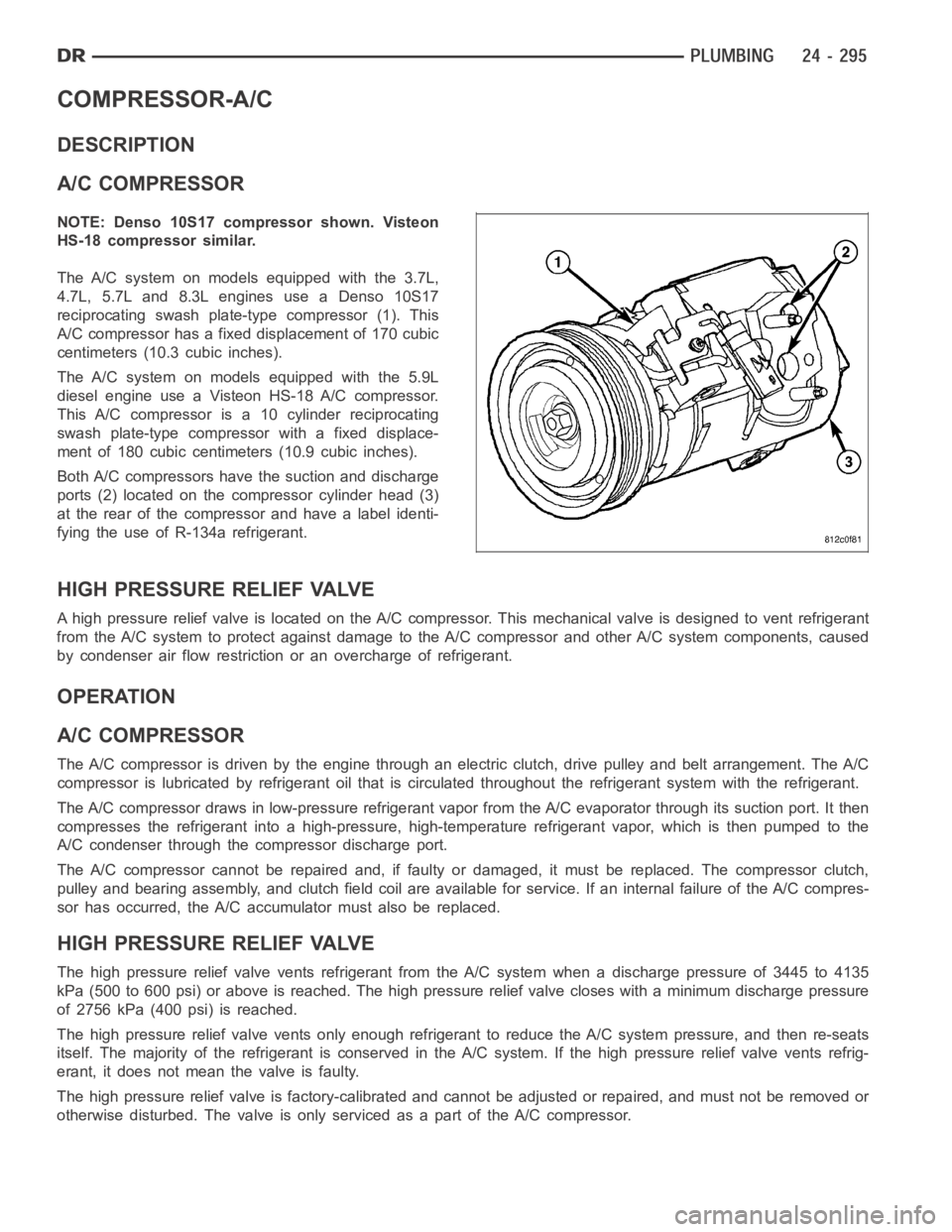
NOTE: Denso 10S17 compressor shown. Visteon
HS-18 compressor similar.
The A/C system on models equipped with the 3.7L,
4.7L, 5.7L and 8.3L engines use a Denso 10S17
reciprocating swash plate-type compressor (1). This
A/C compressor has a fixed displacement of 170 cubic
centimeters (10.3 cubic inches).
The A/C system on models equipped with the 5.9L
diesel engine use a Visteon HS-18 A/C compressor.
This A/C compressor is a 10 cylinder reciprocating
swash plate-type compressor with a fixed displace-
ment of 180 cubic centimeters (10.9 cubic inches).
Both A/C compressors have the suction and discharge
ports (2) located on the compressor cylinder head (3)
at the rear of the compressor and have a label identi-
fying the use of R-134a refrigerant.
HIGH PRESSURE RELIEF VALVE
A high pressure relief valve is located on the A/C compressor. This mechanical valve is designed to vent refrigerant
from the A/C system to protect against damage to the A/C compressor and other A/C system components, caused
by condenser air flow restriction or an overcharge of refrigerant.
OPERATION
A/C COMPRESSOR
The A/C compressor is driven by the engine through an electric clutch, drive pulley and belt arrangement. The A/C
compressor is lubricated by refrigerant oil that is circulated throughout the refrigerant system with the refrigerant.
The A/C compressor draws in low-pressure refrigerant vapor from the A/C evaporator through its suction port. It then
compresses the refrigerant into a high-pressure, high-temperature refrigerant vapor, which is then pumped to the
A/C condenser through the compressor discharge port.
The A/C compressor cannot be repaired and, if faulty or damaged, it must be replaced. The compressor clutch,
pulley and bearing assembly, and clutch field coil are available for service. If an internal failure of the A/C compres-
sor has occurred, the A/C accumulator must also be replaced.
HIGH PRESSURE RELIEF VALVE
The high pressure relief valve vents refrigerant from the A/C system when adischarge pressure of 3445 to 4135
kPa (500 to 600 psi) or above is reached. The high pressure relief valve closes with a minimum discharge pressure
of 2756 kPa (400 psi) is reached.
The high pressure relief valve vents only enough refrigerant to reduce theA/C system pressure, and then re-seats
itself. The majority of the refrigerant is conserved in the A/C system. If the high pressure relief valve vents refrig-
erant, it does not mean the valve is faulty.
The high pressure relief valve is factory-calibrated and cannot be adjusted or repaired, and must not be removed or
otherwise disturbed. The valve is only serviced as a part of the A/C compressor.
Page 5146 of 5267
CONDENSER-A/C
DESCRIPTION
The A/C condenser is located in the front of the engine compartment behind the grille. The A/C condenser is a heat
exchanger that allows the high-pressure refrigerant gas being dischargedbytheA/Ccompressortogiveupitsheat
to the air passing over the condenser fins, which causes the refrigerant tocool and change to a liquid state.
OPERATION
When air passes through the fins of the A/C condenser, the high-pressure refrigerant gas within the A/C condenser
gives up its heat. The refrigerant then condenses as it leaves the A/C condenser and becomes a high-pressure
liquid. The volume of air flowing over the condenser fins is critical to theproper cooling performance of the A/C
system. Therefore, it is important that there are no objects placed in front of the radiator grille openings at the front
of the vehicle or foreign material on the condenser fins that might obstruct proper air flow. Also, any factory-installed
air seals or shrouds must be properly reinstalled following radiator or A/C condenser service.
The A/C condenser cannot be repaired and, if faulty or damaged, it must be replaced.
REMOVAL
3.7L/4.7L/5.7L ENGINES
WARNING: Refer to the applicable warnings and cautions for this system before performing the following
operation (Refer to 24 - HEATING & AIR CONDITIONING/PLUMBING - WARNINGS) and (Refer to 24 - HEAT-
ING & AIR CONDITIONING/PLUMBING - CAUTIONS). Failure to follow the warnings and cautions could result
in possible personal injury or death.
1. Recover the refrigerant from the refrigerant system
(Refer to 24 - HEATING & AIR CONDITIONING/
PLUMBING - STANDARD PROCEDURE -
REFRIGERANT SYSTEM RECOVERY).
2. Disconnect and isolate the negative battery cable.
3. Disconnect the A/C discharge line and the A/C liq-
uidlinefromtheA/Ccondenser(Referto24-
HEATING & AIR CONDITIONING/PLUMBING/
LINE-A/C DISCHARGE - REMOVAL) and (Refer to
24 - HEATING & AIR CONDITIONING/PLUMBING/
LINE-A/C LIQUID - REMOVAL).
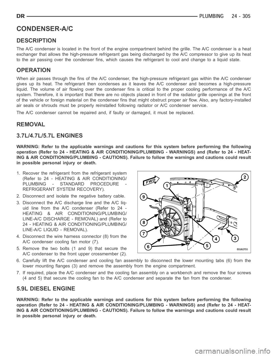
4. Disconnect the wire harness connector (8) from the
A/C condenser cooling fan motor (7).
5. Remove the two bolts (1 and 9) that secure the
A/C condenser to the front upper crossmember (2).
6. Carefully lift the A/C condenser and cooling fan assembly to disconnectthe lower mounting tabs (6) from the
lower mounting flanges (3) and remove the assembly from the engine compartment.
7. If required, place the A/C condenser and the cooling fan assembly on a workbench and remove the four screws
(4 and 5) that secure the cooling fan to the A/C condenser and separate the fan from the condenser.
5.9L DIESEL ENGINE
WARNING: Refer to the applicable warnings and cautions for this system before performing the following
operation (Refer to 24 - HEATING & AIR CONDITIONING/PLUMBING - WARNINGS) and (Refer to 24 - HEAT-
ING & AIR CONDITIONING/PLUMBING - CAUTIONS). Failure to follow the warnings and cautions could result
in possible personal injury or death.
Page 5151 of 5267
CORE-HEATER
DESCRIPTION
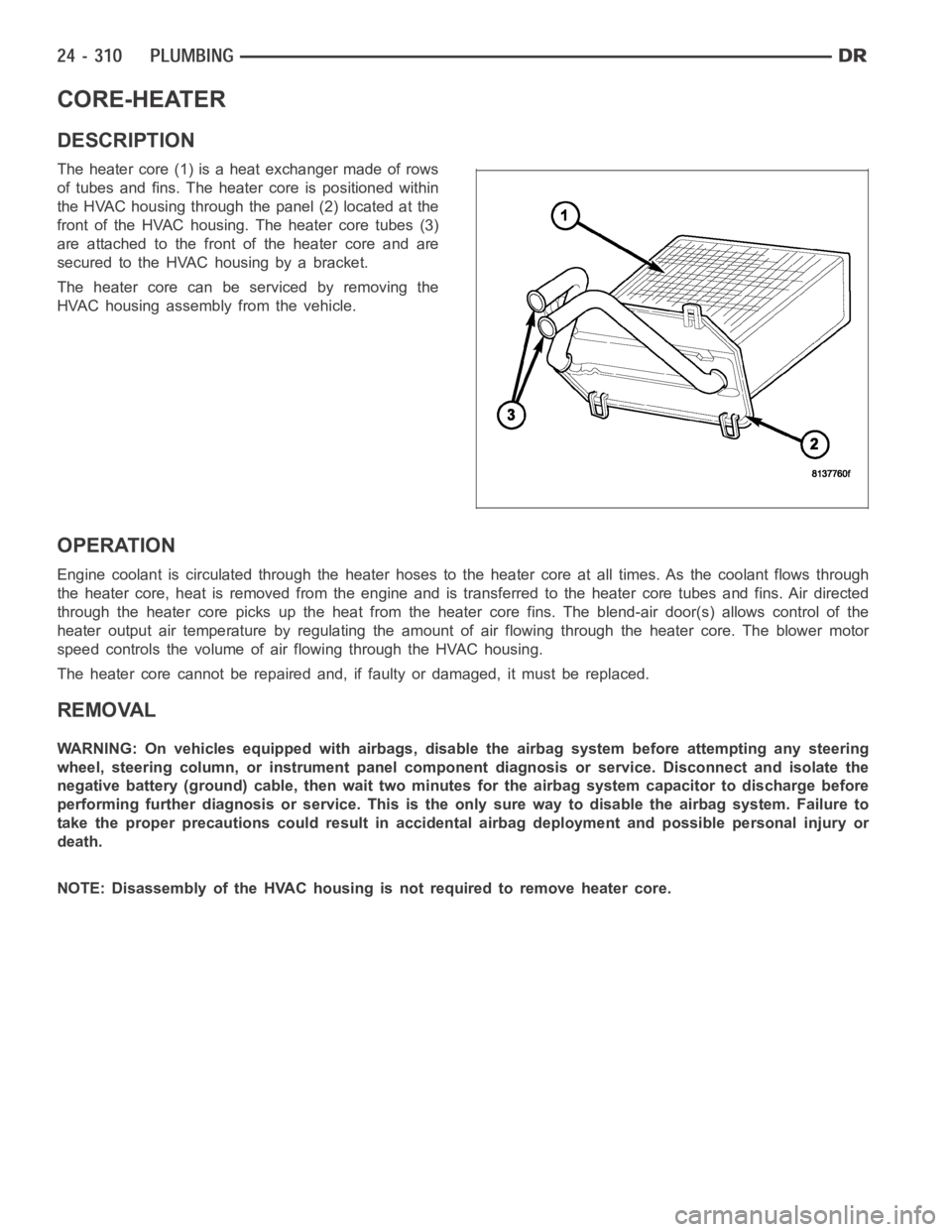
The heater core (1) is a heat exchanger made of rows
of tubes and fins. The heater core is positioned within
the HVAC housing through the panel (2) located at the
front of the HVAC housing. The heater core tubes (3)
are attached to the front of the heater core and are
secured to the HVAC housing by a bracket.
The heater core can be serviced by removing the
HVAC housing assembly from the vehicle.
OPERATION
Engine coolant is circulated through the heater hoses to the heater core atall times. As the coolant flows through
the heater core, heat is removed from the engine and is transferred to the heater core tubes and fins. Air directed
through the heater core picks up the heat from the heater core fins. The blend-air door(s) allows control of the
heater output air temperature by regulating the amount of air flowing through the heater core. The blower motor
speed controls the volume of air flowing through the HVAC housing.
The heater core cannot be repaired and, if faulty or damaged, it must be replaced.
REMOVAL
WARNING: On vehicles equipped with airbags, disable the airbag system before attempting any steering
wheel, steering column, or instrument panel component diagnosis or service. Disconnect and isolate the
negative battery (ground) cable, then wait two minutes for the airbag system capacitor to discharge before
performing further diagnosis or service. This is the only sure way to disable the airbag system. Failure to
take the proper precautions could result in accidental airbag deploymentand possible personal injury or
death.
NOTE: Disassembly of the HVAC housing is not required to remove heater core.
Page 5153 of 5267
CORE-VALVE-SERVICE PORT
DESCRIPTION
Two refrigerant system service ports are used to recover/recycle/evacuate/charge and test the A/C refrigerant sys-
tem. Unique sizes are used on the service ports for the R-134a refrigerant system to ensure the system is not
accidentally contaminated with R-12 refrigerant or service equipment used for R-12 refrigerant.
The high side service port is located on the A/C discharge line. The A/C pressure transducer is mounted on the high
side service port (Refer to 24 - HEATING & AIR CONDITIONING/CONTROLS/TRANSDUCER-A/C PRESSURE -
DESCRIPTION). The low side service port is located either on the top of the A/C accumulator or on the A/C suction
line near the accumulator, depending on engine application. Both the highside and low side A/C service port valve
cores are serviceable.
Each of the service ports has a threaded plastic protective cap installed over it from the factory. After servicing the
refrigerant system, always reinstall both of the service port caps.
REMOVAL
WARNING: Refer to the applicable warnings and cautions for this system before performing the following
operation (Refer to 24 - HEATING & AIR CONDITIONING/PLUMBING - WARNINGS) and (Refer to 24 - HEAT-
ING & AIR CONDITIONING/PLUMBING - CAUTIONS). Failure to follow the warnings and cautions could result
in possible personal injury or death.
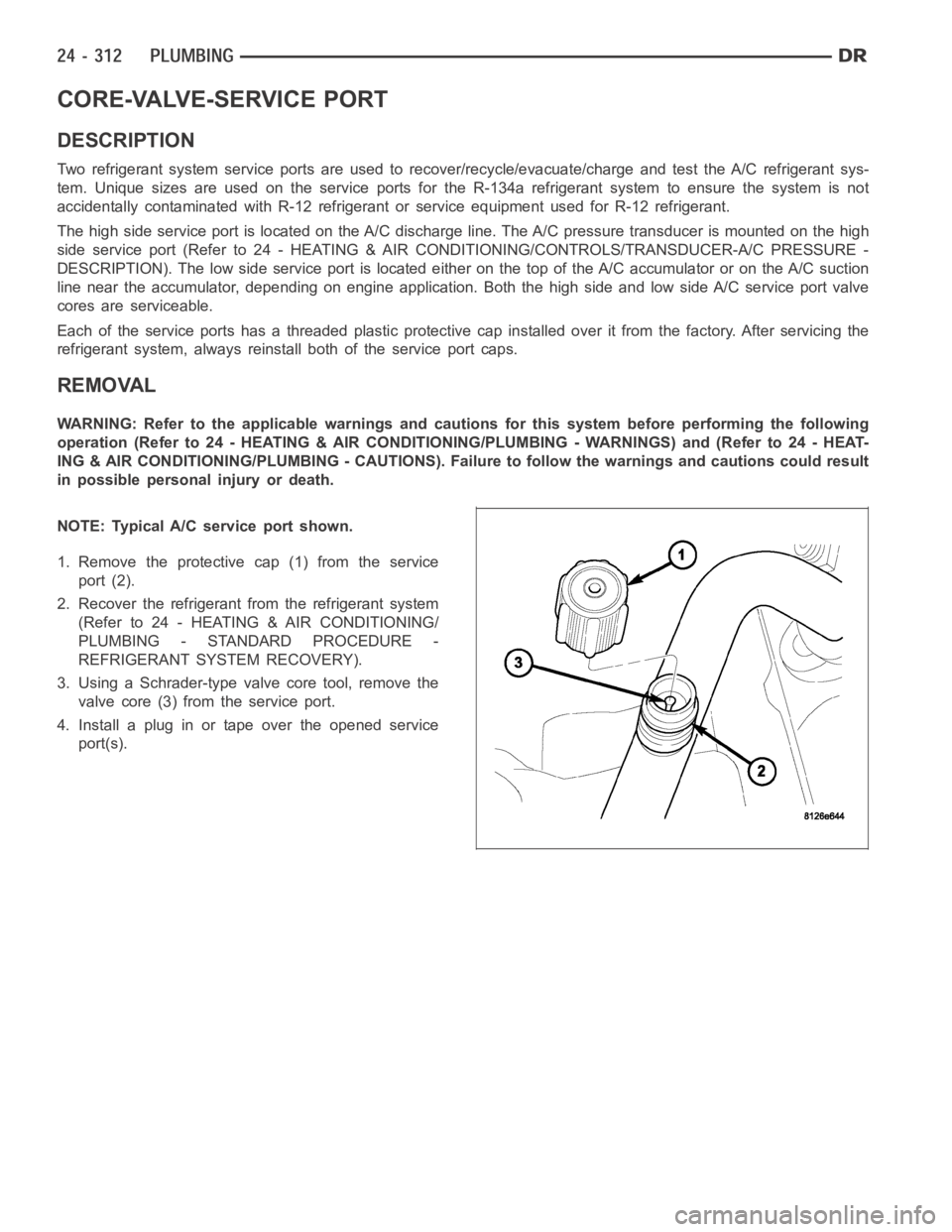
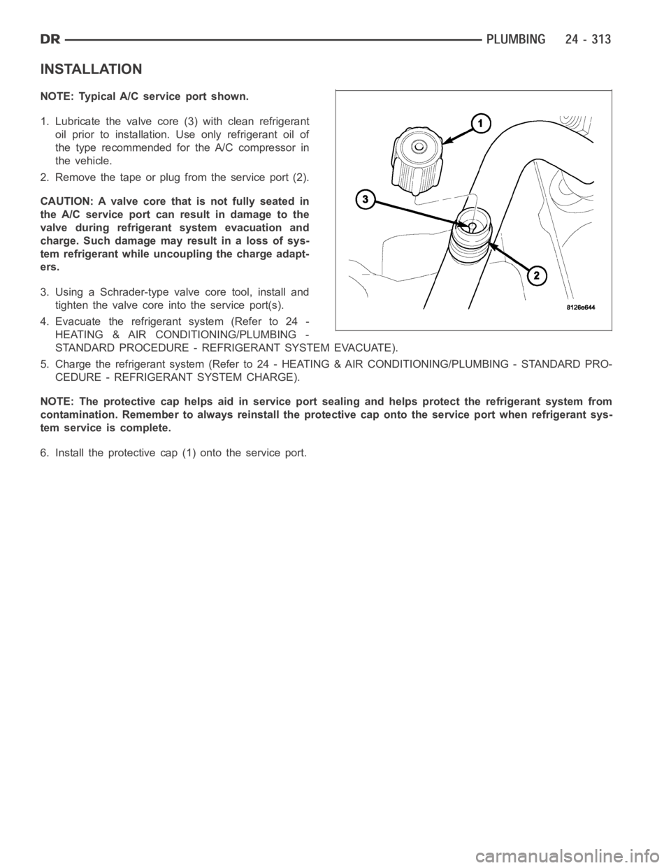
NOTE: Typical A/C service port shown.
1. Remove the protective cap (1) from the service
port (2).
2. Recover the refrigerant from the refrigerant system
(Refer to 24 - HEATING & AIR CONDITIONING/
PLUMBING - STANDARD PROCEDURE -
REFRIGERANT SYSTEM RECOVERY).
3. Using a Schrader-type valve core tool, remove the
valve core (3) from the service port.
4. Install a plug in or tape over the opened service
port(s).
Page 5154 of 5267
INSTALLATION
NOTE: Typical A/C service port shown.
1. Lubricate the valve core (3) with clean refrigerant
oil prior to installation. Use only refrigerant oil of
the type recommended for the A/C compressor in
the vehicle.
2. Remove the tape or plug from the service port (2).
CAUTION: A valve core that is not fully seated in
the A/C service port can result in damage to the
valve during refrigerant system evacuation and
charge. Such damage may result in a loss of sys-
tem refrigerant while uncoupling the charge adapt-
ers.
3. Using a Schrader-type valve core tool, install and
tighten the valve core into the service port(s).
4. Evacuate the refrigerant system (Refer to 24 -
HEATING & AIR CONDITIONING/PLUMBING -
STANDARD PROCEDURE - REFRIGERANT SYSTEM EVACUATE).
5. Charge the refrigerant system (Refer to 24 - HEATING & AIR CONDITIONING/PLUMBING - STANDARD PRO-
CEDURE - REFRIGERANT SYSTEM CHARGE).
NOTE: The protective cap helps aid in service port sealing and helps protect the refrigerant system from
contamination. Remember to always reinstall the protective cap onto the service port when refrigerant sys-
tem service is complete.
6. Install the protective cap (1) onto the service port.
Page 5158 of 5267
EVAPORATOR-A/C
DESCRIPTION
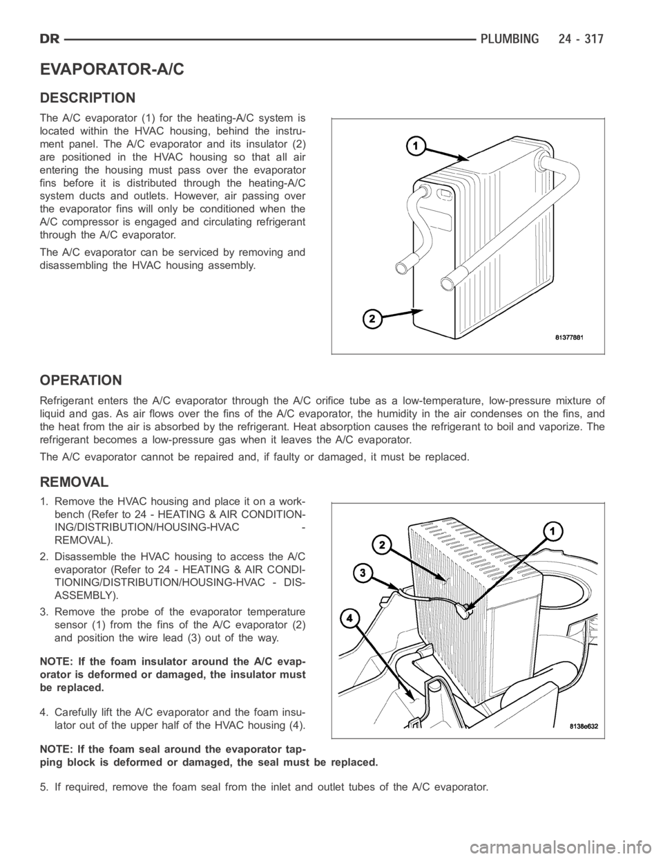
The A/C evaporator (1) for the heating-A/C system is
located within the HVAC housing, behind the instru-
ment panel. The A/C evaporator and its insulator (2)
are positioned in the HVAC housing so that all air
entering the housing must pass over the evaporator
fins before it is distributed through the heating-A/C
system ducts and outlets. However, air passing over
the evaporator fins will only be conditioned when the
A/C compressor is engaged and circulating refrigerant
through the A/C evaporator.
The A/C evaporator can be serviced by removing and
disassembling the HVAC housing assembly.
OPERATION
Refrigerant enters the A/C evaporator through the A/C orifice tube as a low-temperature, low-pressure mixture of
liquid and gas. As air flows over the fins of the A/C evaporator, the humidity in the air condenses on the fins, and
the heat from the air is absorbed by the refrigerant. Heat absorption causes the refrigerant to boil and vaporize. The
refrigerant becomes a low-pressure gas when it leaves the A/C evaporator.
The A/C evaporator cannot be repaired and, if faulty or damaged, it must be replaced.
REMOVAL
1. RemovetheHVAChousingandplaceitonawork-
bench (Refer to 24 - HEATING & AIR CONDITION-
ING/DISTRIBUTION/HOUSING-HVAC -
REMOVAL).
2. Disassemble the HVAC housing to access the A/C
evaporator (Refer to 24 - HEATING & AIR CONDI-
TIONING/DISTRIBUTION/HOUSING-HVAC - DIS-
ASSEMBLY).
3. Remove the probe of the evaporator temperature
sensor (1) from the fins of the A/C evaporator (2)
and position the wire lead (3) out of the way.
NOTE: If the foam insulator around the A/C evap-
orator is deformed or damaged, the insulator must
be replaced.
4. Carefully lift the A/C evaporator and the foam insu-
lator out of the upper half of the HVAC housing (4).
NOTE: If the foam seal around the evaporator tap-
ping block is deformed or damaged, the seal must be replaced.
5. If required, remove the foam seal from the inlet and outlet tubes of the A/Cevaporator.
Page 5162 of 5267
LINE-A/C DISCHARGE
DESCRIPTION
The A/C discharge line is the refrigerant line that goes from the A/C compressor to the A/C condenser and has an
integral fitting for the A/C pressure transducer (Refer to 24 - HEATING & AIR CONDITIONING/CONTROLS/TRANS-
DUCER-A/C PRESSURE - DESCRIPTION).
The A/C discharge line for the 5.9L Diesel engine is serviced as an assemblywith the suction line.
The A/C discharge line for the 8.3L engine is secured to the top of fan shroudby two retainers.
CAUTION: Use only O-ring seals specified for the vehicle. Failure to use correct O-ring seal will cause the
refrigerant system connection to leak.
The A/C discharge line has no serviceable parts except the rubber O-ring seals. The O-ring seals used on the
connections are made from a special type of rubber not affected by R-134a refrigerant. The O-ring seals must be
replaced whenever the A/C discharge line is removed and installed.
If the A/C discharge line is found to be leaking or is damaged, it must be replaced.
REMOVAL
3.7L/4.7L ENGINES
WARNING: Refer to the applicable warnings and cautions for this system before performing the following
operation (Refer to 24 - HEATING & AIR CONDITIONING/PLUMBING - WARNINGS) and (Refer to 24 - HEAT-
ING & AIR CONDITIONING/PLUMBING - CAUTIONS). Failure to follow the warnings and cautions could result
in possible personal injury or death.
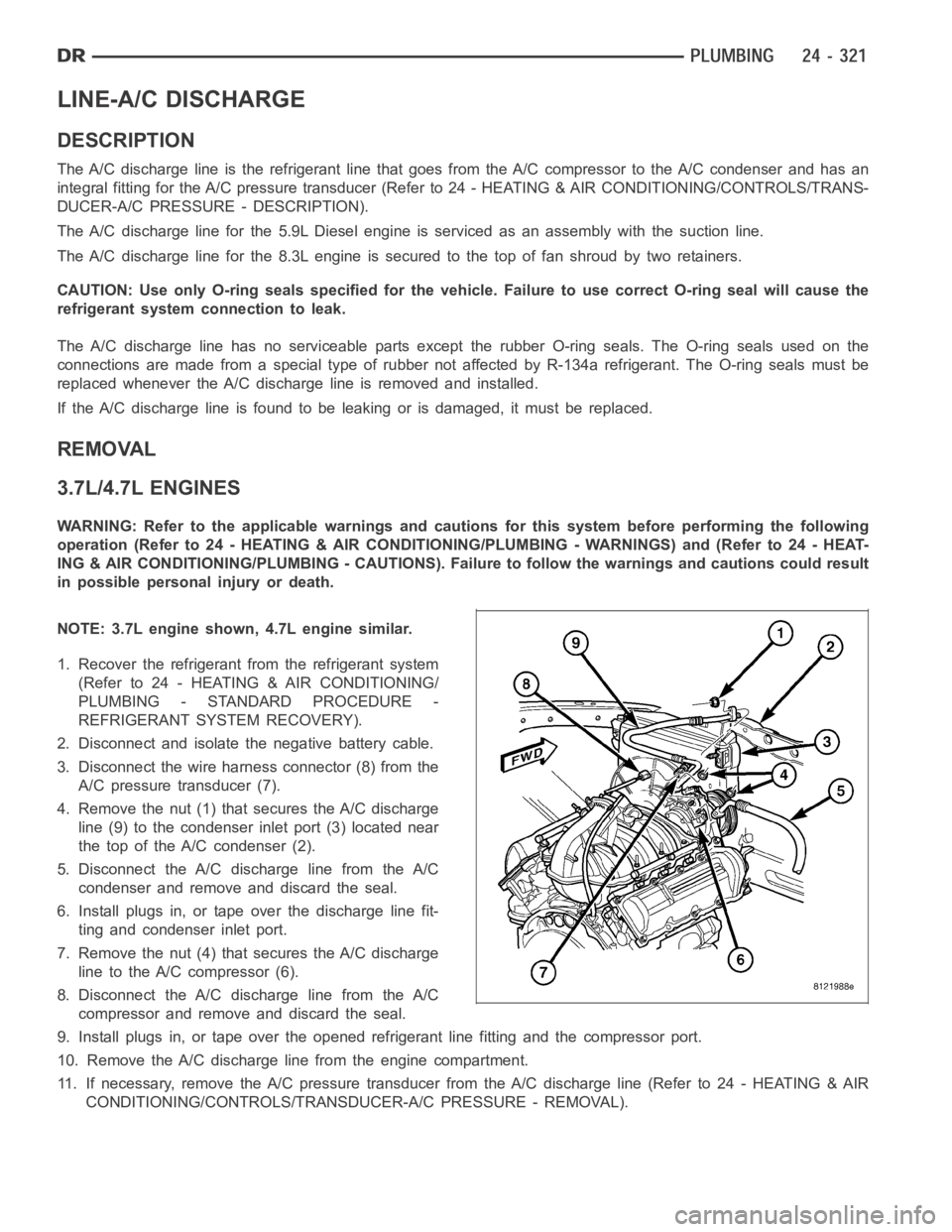
NOTE: 3.7L engine shown, 4.7L engine similar.
1. Recover the refrigerant from the refrigerant system
(Refer to 24 - HEATING & AIR CONDITIONING/
PLUMBING - STANDARD PROCEDURE -
REFRIGERANT SYSTEM RECOVERY).
2. Disconnect and isolate the negative battery cable.
3. Disconnect the wire harness connector (8) from the
A/C pressure transducer (7).
4. Remove the nut (1) that secures the A/C discharge
line (9) to the condenser inlet port (3) located near
the top of the A/C condenser (2).
5. Disconnect the A/C discharge line from the A/C
condenser and remove and discard the seal.
6. Install plugs in, or tape over the discharge line fit-
ting and condenser inlet port.
7. Remove the nut (4) that secures the A/C discharge
line to the A/C compressor (6).
8. Disconnect the A/C discharge line from the A/C
compressor and remove and discard the seal.
9. Install plugs in, or tape over the opened refrigerant line fitting and the compressor port.
10. Remove the A/C discharge line from the engine compartment.
11. If necessary, remove the A/C pressure transducer from the A/C dischargeline(Referto24-HEATING&AIR
CONDITIONING/CONTROLS/TRANSDUCER-A/C PRESSURE - REMOVAL).
Page 5163 of 5267
5.7L ENGINE
WARNING: Refer to the applicable warnings and cautions for this system before performing the following
operation (Refer to 24 - HEATING & AIR CONDITIONING/PLUMBING - WARNINGS) and (Refer to 24 - HEAT-
ING & AIR CONDITIONING/PLUMBING - CAUTIONS). Failure to follow the warnings and cautions could result
in possible personal injury or death.
1. Recover the refrigerant from the refrigerant system
(Refer to 24 - HEATING & AIR CONDITIONING/
PLUMBING - STANDARD PROCEDURE -
REFRIGERANT SYSTEM RECOVERY).
2. Disconnect and isolate the negative battery cable.
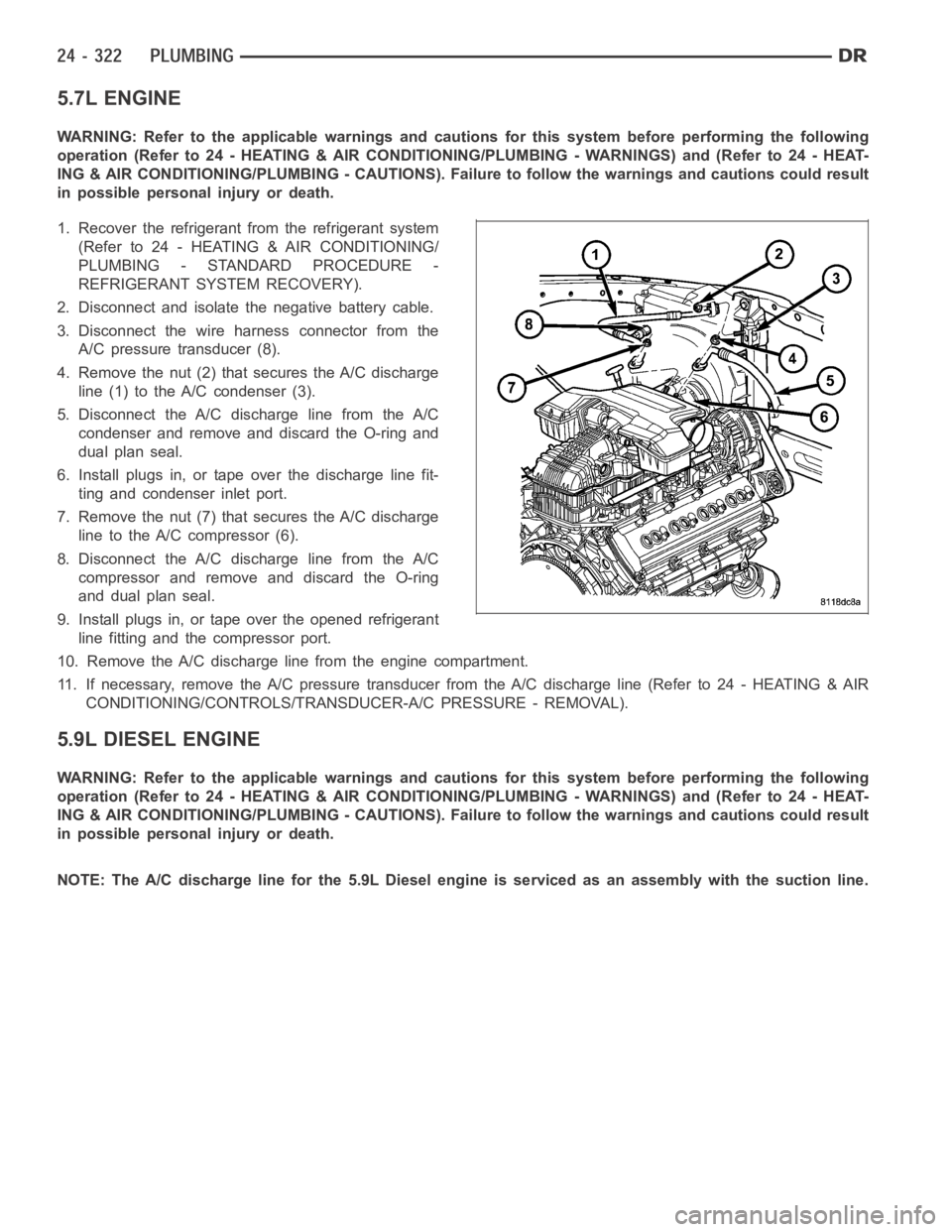
3. Disconnect the wire harness connector from the
A/C pressure transducer (8).
4. Remove the nut (2) that secures the A/C discharge
line (1) to the A/C condenser (3).
5. Disconnect the A/C discharge line from the A/C
condenser and remove and discard the O-ring and
dual plan seal.
6. Install plugs in, or tape over the discharge line fit-
ting and condenser inlet port.
7. Remove the nut (7) that secures the A/C discharge
line to the A/C compressor (6).
8. Disconnect the A/C discharge line from the A/C
compressor and remove and discard the O-ring
and dual plan seal.
9. Install plugs in, or tape over the opened refrigerant
line fitting and the compressor port.
10. Remove the A/C discharge line from the engine compartment.
11. If necessary, remove the A/C pressure transducer from the A/C dischargeline(Referto24-HEATING&AIR
CONDITIONING/CONTROLS/TRANSDUCER-A/C PRESSURE - REMOVAL).
5.9L DIESEL ENGINE
WARNING: Refer to the applicable warnings and cautions for this system before performing the following
operation (Refer to 24 - HEATING & AIR CONDITIONING/PLUMBING - WARNINGS) and (Refer to 24 - HEAT-
ING & AIR CONDITIONING/PLUMBING - CAUTIONS). Failure to follow the warnings and cautions could result
in possible personal injury or death.
NOTE: The A/C discharge line for the 5.9L Diesel engine is serviced as an assembly with the suction line.