2006 DODGE RAM SRT-10 service
[x] Cancel search: servicePage 5105 of 5267
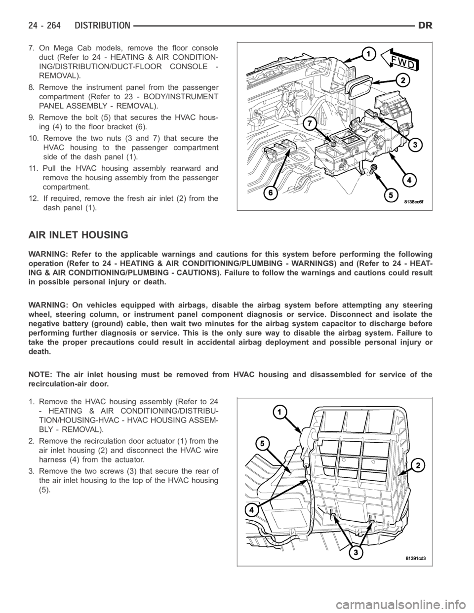
7. On Mega Cab models, remove the floor console
duct (Refer to 24 - HEATING & AIR CONDITION-
ING/DISTRIBUTION/DUCT-FLOOR CONSOLE -
REMOVAL).
8. Remove the instrument panel from the passenger
compartment (Refer to 23 - BODY/INSTRUMENT
PANEL ASSEMBLY - REMOVAL).
9. Remove the bolt (5) that secures the HVAC hous-
ing (4) to the floor bracket (6).
10. Remove the two nuts (3 and 7) that secure the
HVAC housing to the passenger compartment
side of the dash panel (1).
11. Pull the HVAC housing assembly rearward and
remove the housing assembly from the passenger
compartment.
12. If required, remove the fresh air inlet (2) from the
dash panel (1).
AIR INLET HOUSING
WARNING: Refer to the applicable warnings and cautions for this system before performing the following
operation (Refer to 24 - HEATING & AIR CONDITIONING/PLUMBING - WARNINGS) and (Refer to 24 - HEAT-
ING & AIR CONDITIONING/PLUMBING - CAUTIONS). Failure to follow the warnings and cautions could result
in possible personal injury or death.
WARNING: On vehicles equipped with airbags, disable the airbag system before attempting any steering
wheel, steering column, or instrument panel component diagnosis or service. Disconnect and isolate the
negative battery (ground) cable, then wait two minutes for the airbag system capacitor to discharge before
performing further diagnosis or service. This is the only sure way to disable the airbag system. Failure to
take the proper precautions could result in accidental airbag deploymentand possible personal injury or
death.
NOTE: The air inlet housing must be removed from HVAC housing and disassembled for service of the
recirculation-air door.
1. Remove the HVAC housing assembly (Refer to 24
- HEATING & AIR CONDITIONING/DISTRIBU-
TION/HOUSING-HVAC - HVAC HOUSING ASSEM-
BLY - REMOVAL).
2. Remove the recirculation door actuator (1) from the
air inlet housing (2) and disconnect the HVAC wire
harness (4) from the actuator.
3. Remove the two screws (3) that secure the rear of
the air inlet housing to the top of the HVAC housing
(5).
Page 5106 of 5267
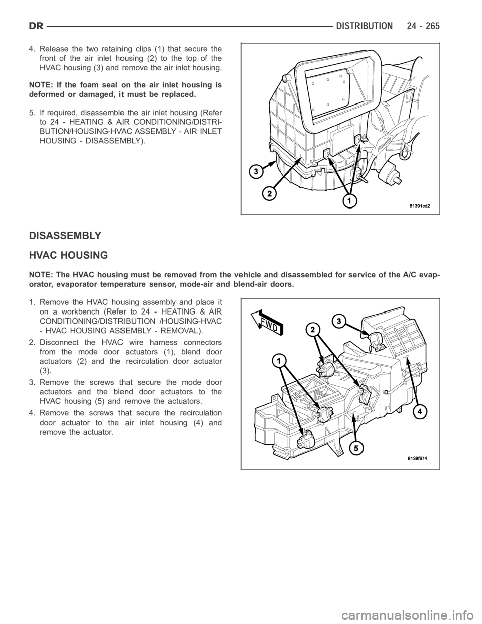
4. Release the two retaining clips (1) that secure the
front of the air inlet housing (2) to the top of the
HVAC housing (3) and remove the air inlet housing.
NOTE: If the foam seal on the air inlet housing is
deformed or damaged, it must be replaced.
5. If required, disassemblethe air inlet housing (Refer
to 24 - HEATING & AIR CONDITIONING/DISTRI-
BUTION/HOUSING-HVAC ASSEMBLY - AIR INLET
HOUSING - DISASSEMBLY).
DISASSEMBLY
HVAC HOUSING
NOTE: The HVAC housing must be removedfrom the vehicle and disassembled for service of the A/C evap-
orator, evaporator temperature sensor, mode-air and blend-air doors.
1. Remove the HVAC housing assembly and place it
on a workbench (Refer to 24 - HEATING & AIR
CONDITIONING/DISTRIBUTION /HOUSING-HVAC
- HVAC HOUSING ASSEMBLY - REMOVAL).
2. Disconnect the HVAC wire harness connectors
from the mode door actuators (1), blend door
actuators (2) and the recirculation door actuator
(3).
3. Remove the screws that secure the mode door
actuators and the blend door actuators to the
HVAC housing (5) and remove the actuators.
4. Remove the screws that secure the recirculation
door actuator to the air inlet housing (4) and
remove the actuator.
Page 5110 of 5267
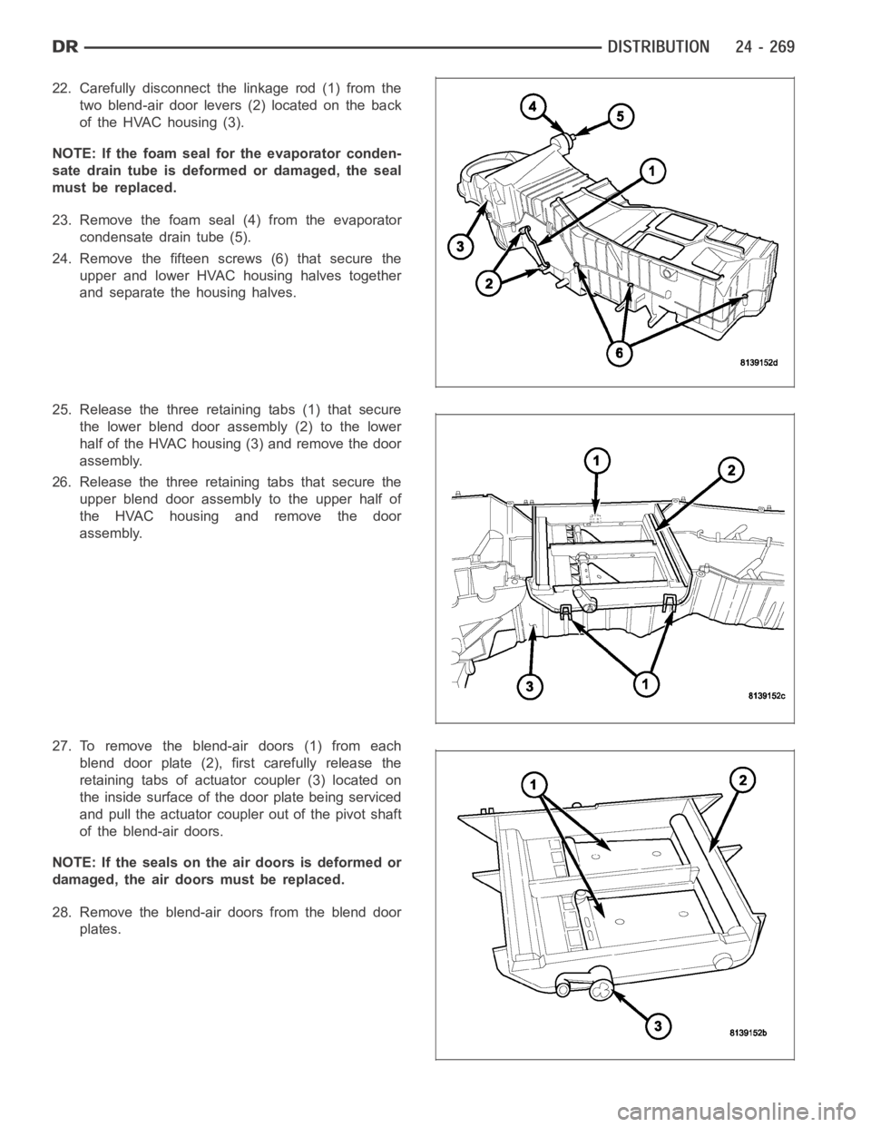
22. Carefully disconnect the linkage rod (1) from the
two blend-air door levers (2) located on the back
of the HVAC housing (3).
NOTE: If the foam seal for the evaporator conden-
sate drain tube is deformed or damaged, the seal
must be replaced.
23. Remove the foam seal (4) from the evaporator
condensate drain tube (5).
24. Remove the fifteen screws (6) that secure the
upper and lower HVAC housing halves together
and separate the housing halves.
25. Release the three retaining tabs (1) that secure
the lower blend door assembly (2) to the lower
half of the HVAC housing (3) and remove the door
assembly.
26. Release the three retaining tabs that secure the
upper blend door assembly to the upper half of
the HVAC housing and remove the door
assembly.
27. To remove the blend-air doors (1) from each
blend door plate (2), first carefully release the
retaining tabs of actuator coupler (3) located on
the inside surface of the door plate being serviced
and pull the actuator coupler out of the pivot shaft
of the blend-air doors.
NOTE: If the seals on the air doors is deformed or
damaged, the air doors must be replaced.
28. Remove the blend-air doors from the blend door
plates.
Page 5111 of 5267
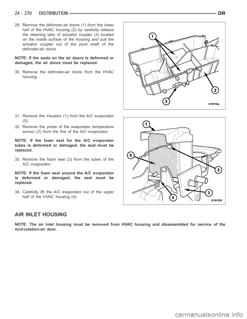
29. Remove the defroster-air doors (1) from the lower
half of the HVAC housing (2) by carefully release
the retaining tabs of actuator coupler (3) located
on the inside surface of the housing and pull the
actuator coupler out of the pivot shaft of the
defroster-air doors.
NOTE: If the seals on the air doors is deformed or
damaged, the air doors must be replaced.
30. Remove the defroster-air doors from the HVAC
housing.
31. Remove the insulator (1) from the A/C evaporator
(5).
32. Remove the probe of the evaporator temperature
sensor (2) from the fins of the A/C evaporator.
NOTE: If the foam seal for the A/C evaporator
tubes is deformed or damaged, the seal must be
replaced.
33. Remove the foam seal (3) from the tubes of the
A/C evaporator.
NOTE: If the foam seal around the A/C evaporator
is deformed or damaged, the seal must be
replaced.
34. Carefully lift the A/C evaporator out of the upper
half of the HVAC housing (4).
AIR INLET HOUSING
NOTE: The air inlet housing must be removed from HVAC housing and disassembled for service of the
recirculation-air door.
Page 5118 of 5267

AIR INLET HOUSING
NOTE: The air inlet housing must be removed from HVAC housing and disassembled for service of the
recirculation-air door.
NOTE: If the seals on the air door is deformed or
damaged, the air door must be replaced.
1. Position the recirculation-air door (1) into the air
inlet housing (2).
CAUTION: Make sure that the recirculation-air
door pivot shaft is properly seated in the pivot
seat located in the air inlet housing.
2. Align the actuator coupler (3) with the recirculation-
air door pivot shaft and install the coupler until the
coupler retaining tabs are fully engaged to the air
inlet housing. Be sure to install the coupler with the
coupler arm located between the two stop tabs on
the air inlet housing.
3. Install the two foam insulators (2) into the air inlet
housing (1).
4. Install the air inlet housing onto the HVAC housing
(Refer to 24 - HEATING & AIR CONDITIONING/
DISTRIBUTION/HOUSING-HVAC - AIR INLET
HOUSING - INSTALLATION).
INSTALLATION
HVAC HOUSING ASSEMBLY
NOTE: The HVAC housing must be removedfrom the vehicle and disassembled for service of the A/C evap-
orator, evaporator temperature sensor, mode-air and blend-air doors.
Page 5119 of 5267
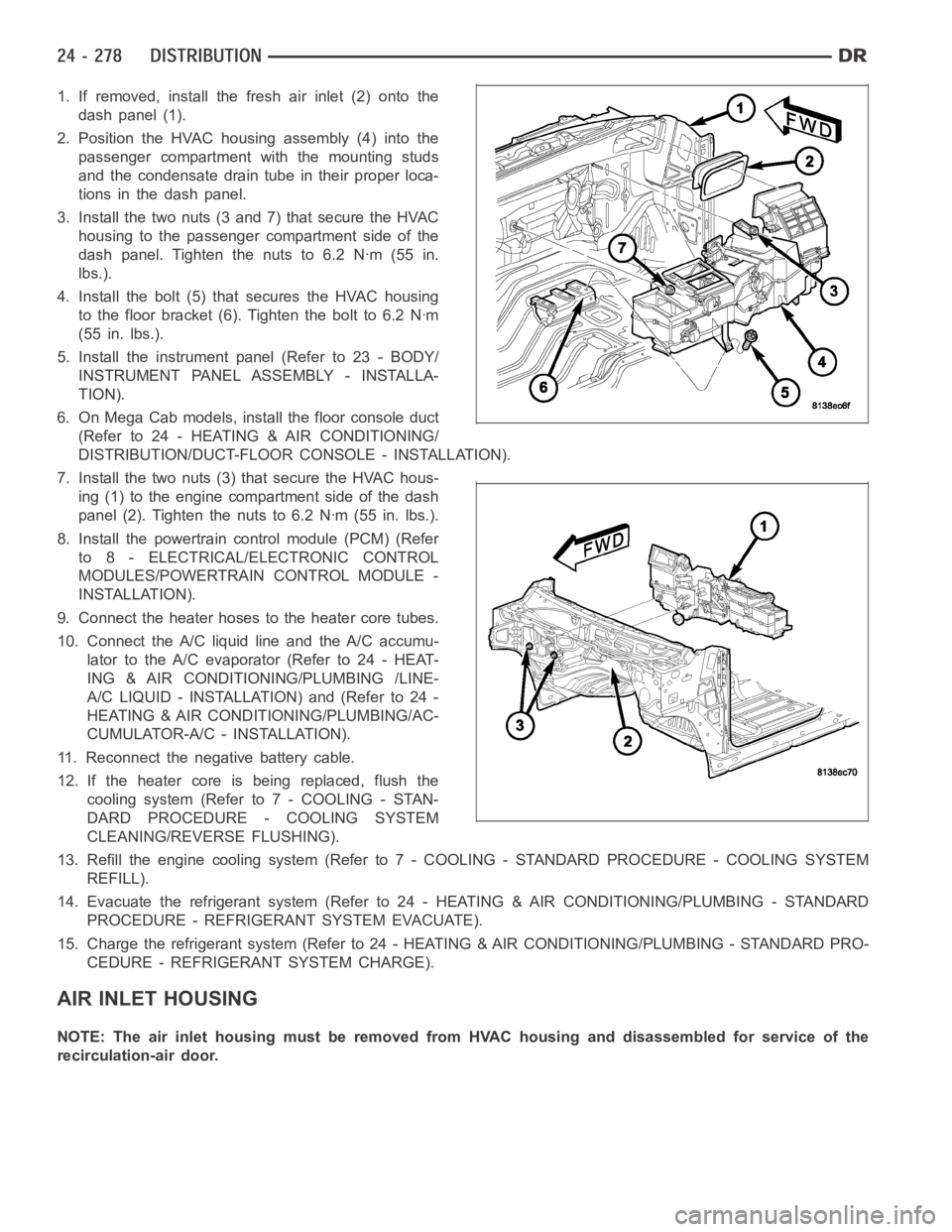
1. If removed, install the fresh air inlet (2) onto the
dash panel (1).
2. Position the HVAC housing assembly (4) into the
passenger compartment with the mounting studs
and the condensate drain tube in their proper loca-
tions in the dash panel.
3. Install the two nuts (3 and 7) that secure the HVAC
housing to the passenger compartment side of the
dash panel. Tighten the nuts to 6.2 Nꞏm (55 in.
lbs.).
4. Install the bolt (5) that secures the HVAC housing
to the floor bracket (6). Tighten the bolt to 6.2 Nꞏm
(55 in. lbs.).
5. Install the instrument panel (Refer to 23 - BODY/
INSTRUMENT PANEL ASSEMBLY - INSTALLA-
TION).
6. On Mega Cab models, install the floor console duct
(Refer to 24 - HEATING & AIR CONDITIONING/
DISTRIBUTION/DUCT-FLOOR CONSOLE - INSTALLATION).
7. Install the two nuts (3) that secure the HVAC hous-
ing (1) to the engine compartment side of the dash
panel (2). Tighten the nuts to 6.2 Nꞏm (55 in. lbs.).
8. Install the powertrain control module (PCM) (Refer
to 8 - ELECTRICAL/ELECTRONIC CONTROL
MODULES/POWERTRAIN CONTROL MODULE -
INSTALLATION).
9. Connect the heater hoses to the heater core tubes.
10. Connect the A/C liquid line and the A/C accumu-
lator to the A/C evaporator (Refer to 24 - HEAT-
ING & AIR CONDITIONING/PLUMBING /LINE-
A/C LIQUID - INSTALLATION) and (Refer to 24 -
HEATING & AIR CONDITIONING/PLUMBING/AC-
CUMULATOR-A/C - INSTALLATION).
11. Reconnect the negative battery cable.
12. If the heater core is being replaced, flush the
coolingsystem(Referto7-COOLING-STAN-
DARD PROCEDURE - COOLING SYSTEM
CLEANING/REVERSE FLUSHING).
13. Refill the engine cooling system (Refer to 7 - COOLING - STANDARD PROCEDURE - COOLING SYSTEM
REFILL).
14. Evacuate the refrigerant system (Refer to 24 - HEATING & AIR CONDITIONING/PLUMBING - STANDARD
PROCEDURE - REFRIGERANT SYSTEM EVACUATE).
15. Charge the refrigerant system (Refer to 24 - HEATING & AIR CONDITIONING/PLUMBING - STANDARD PRO-
CEDURE - REFRIGERANT SYSTEM CHARGE).
AIR INLET HOUSING
NOTE: The air inlet housing must be removed from HVAC housing and disassembled for service of the
recirculation-air door.
Page 5121 of 5267
MOTOR-BLOWER
DESCRIPTION
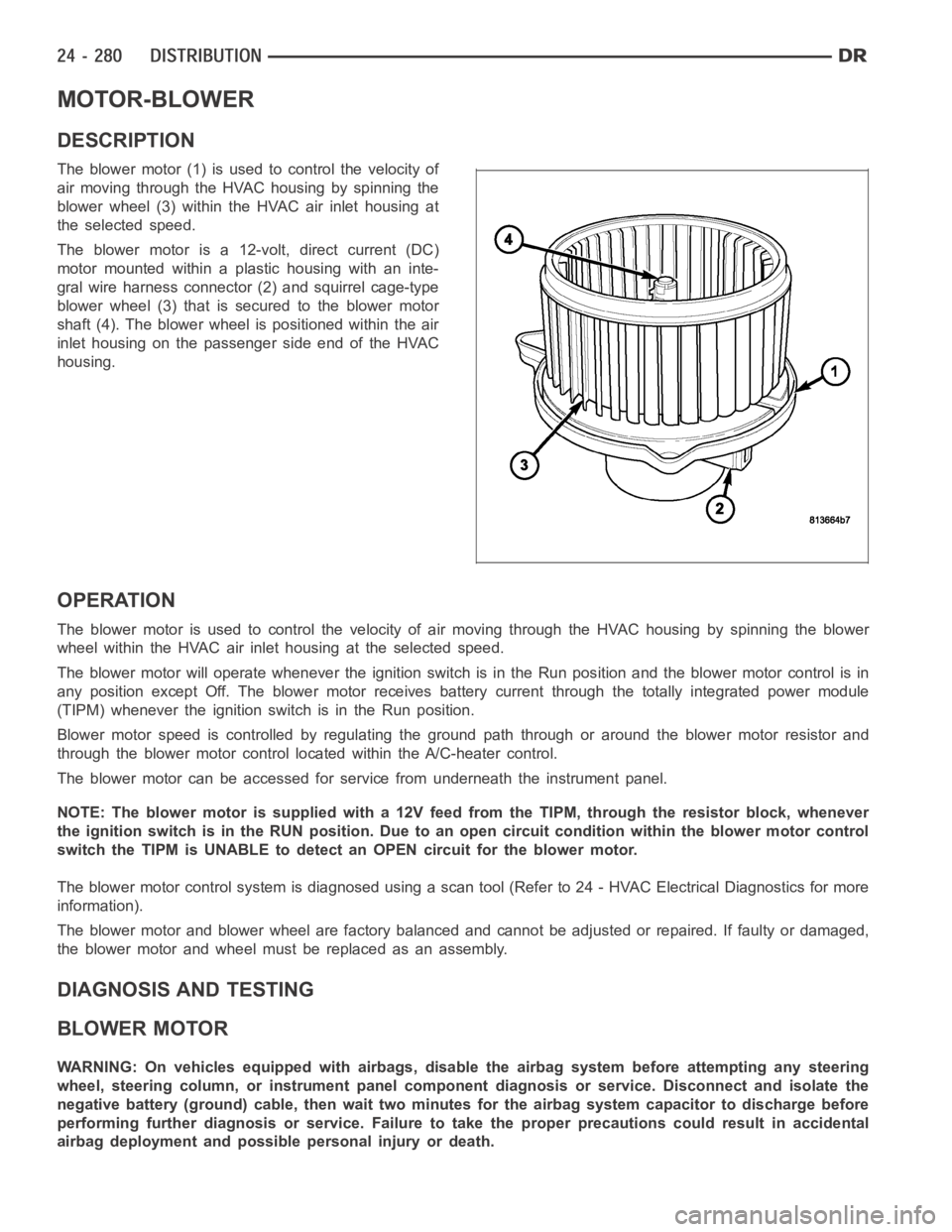
The blower motor (1) is used to control the velocity of
air moving through the HVAC housing by spinning the
blower wheel (3) within the HVAC air inlet housing at
the selected speed.
The blower motor is a 12-volt, direct current (DC)
motormountedwithinaplastichousingwithaninte-
gral wire harness connector (2) and squirrel cage-type
blower wheel (3) that is secured to the blower motor
shaft (4). The blower wheel is positioned within the air
inlet housing on the passenger side end of the HVAC
housing.
OPERATION
The blower motor is used to control the velocity of air moving through the HVAC housing by spinning the blower
wheel within the HVAC air inlet housing at the selected speed.
The blower motor will operate whenever the ignition switch is in the Run position and the blower motor control is in
any position except Off. The blower motor receives battery current through the totally integrated power module
(TIPM) whenever the ignition switch is in the Run position.
Blower motor speed is controlled by regulating the ground path through or around the blower motor resistor and
through the blower motor control located within the A/C-heater control.
The blower motor can be accessed for service from underneath the instrument panel.
NOTE: The blower motor is supplied with a 12V feed from the TIPM, through theresistor block, whenever
the ignition switch is in the RUN position. Due to an open circuit conditionwithin the blower motor control
switch the TIPM is UNABLE to detect an OPEN circuit for the blower motor.
The blower motor control system is diagnosed using a scan tool (Refer to 24 -HVAC Electrical Diagnostics for more
information).
The blower motor and blower wheel are factory balanced and cannot be adjusted or repaired. If faulty or damaged,
the blower motor and wheel must be replaced as an assembly.
DIAGNOSIS AND TESTING
BLOWER MOTOR
WARNING: On vehicles equipped with airbags, disable the airbag system before attempting any steering
wheel, steering column, or instrument panel component diagnosis or service. Disconnect and isolate the
negative battery (ground) cable, then wait two minutes for the airbag system capacitor to discharge before
performing further diagnosis or service. Failure to take the proper precautions could result in accidental
airbag deployment and possible personal injury or death.
Page 5124 of 5267
OUTLETS-AIR
DESCRIPTION
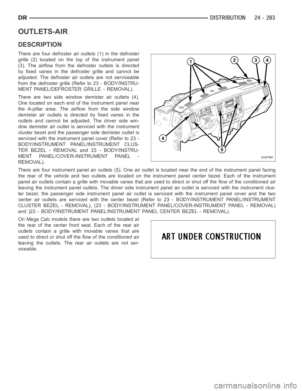
There are four defroster air outlets (1) in the defroster
grille (2) located on the top of the instrument panel
(3). The airflow from the defroster outlets is directed
by fixed vanes in the defroster grille and cannot be
adjusted. The defroster air outlets are not serviceable
from the defroster grille (Refer to 23 - BODY/INSTRU-
MENT PANEL/DEFROSTER GRILLE - REMOVAL).
There are two side window demister air outlets (4).
One located on each end of the instrument panel near
the A-pillar area. The airflow from the side window
demister air outlets is directed by fixed vanes in the
outlets and cannot be adjusted. The driver side win-
dow demister air outlet is serviced with the instrument
cluster bezel and the passenger side demister outlet is
serviced with the instrument panel cover (Refer to 23 -
BODY/INSTRUMENT PANEL/INSTRUMENT CLUS-
TER BEZEL - REMOVAL and 23 - BODY/INSTRU-
MENT PANEL/COVER-INSTRUMENT PANEL -
REMOVAL).
There are four instrument panel air outlets (5). One air outlet is located near the end of the instrument panel facing
the rear of the vehicle and two outlets are located on the instrument panel center bezel. Each of the instrument
panel air outlets contain a grille with movable vanes that are used to direct or shut off the flow of the conditioned air
leaving the instrument panel outlets. The driver side instrument panel air outlet is serviced with the instrument clus-
ter bezel, the passenger side instrument panel air outlet is serviced withthe instrument panel cover and the two
center air outlets are serviced with the center bezel (Refer to 23 - BODY/INSTRUMENT PANEL/INSTRUMENT
CLUSTER BEZEL - REMOVAL), (23 - BODY/INSTRUMENT PANEL/COVER-INSTRUMENTPA N E L - R E M O VA L )
and )23 - BODY/INSTRUMENT PANEL/INSTRUMENT PANEL CENTER BEZEL - REMOVAL).
On Mega Cab models there are two outlets located at
the rear of the center front seat. Each of the rear air
outlets contain a grille withmovable vanes that are
used to direct or shut off the flow of the conditioned air
leaving the outlets. The rear air outlets are not ser-
viceable.