2006 DODGE RAM SRT-10 service
[x] Cancel search: servicePage 5044 of 5267
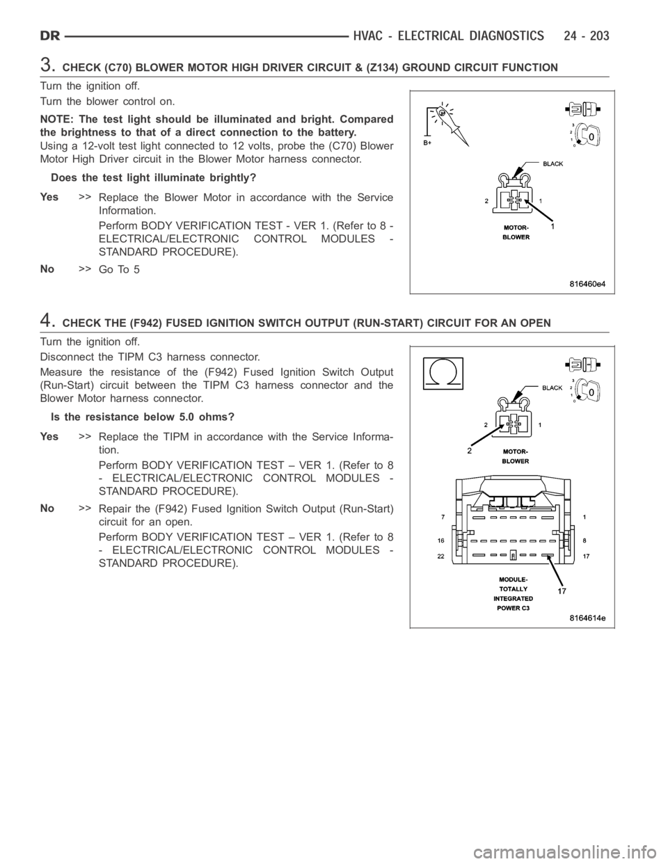
3.CHECK (C70) BLOWER MOTOR HIGH DRIVER CIRCUIT & (Z134) GROUND CIRCUIT FUNCTION
Turn the ignition off.
Turn the blower control on.
NOTE: The test light should be illuminated and bright. Compared
the brightness to that of a direct connection to the battery.
Using a 12-volt test light connected to 12 volts, probe the (C70) Blower
Motor High Driver circuit in the Blower Motor harness connector.
Does the test light illuminate brightly?
Ye s>>
Replace the Blower Motor in accordance with the Service
Information.
Perform BODY VERIFICATION TEST - VER 1. (Refer to 8 -
ELECTRICAL/ELECTRONIC CONTROL MODULES -
STANDARD PROCEDURE).
No>>
Go To 5
4.CHECK THE (F942) FUSED IGNITION SWITCH OUTPUT (RUN-START) CIRCUIT FOR AN OPEN
Turn the ignition off.
Disconnect the TIPM C3 harness connector.
Measure the resistance of the (F942) Fused Ignition Switch Output
(Run-Start) circuit between the TIPM C3 harness connector and the
Blower Motor harness connector.
Is the resistance below 5.0 ohms?
Ye s>>
Replace the TIPM in accordance with the Service Informa-
tion.
Perform BODY VERIFICATION TEST – VER 1. (Refer to 8
- ELECTRICAL/ELECTRONIC CONTROL MODULES -
STANDARD PROCEDURE).
No>>
Repair the (F942) Fused Ignition Switch Output (Run-Start)
circuit for an open.
Perform BODY VERIFICATION TEST – VER 1. (Refer to 8
- ELECTRICAL/ELECTRONIC CONTROL MODULES -
STANDARD PROCEDURE).
Page 5047 of 5267

With the scan tool in HVAC, select System Tests and then select Cooldown test. Allow the test to run to completion.
Does the scan tool display a status message that indicates a fault has occurred?
Yes, Conditions Too Cold - Test Not Run
If running, turn the A/C compressor off. Verify that the work area ambient temperature is above 15.6°C
(60°F). If not, move the vehicle to a warmer work area. Verify that the evaporator temperature is above
13°C (55°F). If not, set the blower to high speed and allow the blower to run for five minutes. Then, run
the Cooldown Test again.
Yes, Blowers Not On High - Test Not Run
Set the blower speed to high speed and then run the Cooldown Test again.
Yes, No Results Stored/Test Not Complete
Verify that power is not interrupted while rerunning the Cooldown Test.
Yes, Refrigerant Temperature Sensor Error
For Dual-Zone HVAC systems, refer to B10B2–A/C COOL DOWN TEST PERFORMANCEfor the diag-
nostic test procedure. For Single-Zone HVAC systems, refer to B1079–CLIMATE CONTROL COOL
DOWN TEST EXCESSIVE TIME for the diagnostic test procedure.
Yes, DTC Set During Routine - Test Not Passed
For Dual-Zone HVAC systems, refer to B10B2–A/C COOL DOWN TEST PERFORMANCEfor the diag-
nostic test procedure. For Single-Zone HVAC systems, refer to B1079–CLIMATE CONTROL COOL
DOWN TEST EXCESSIVE TIME for the diagnostic test procedure.
No>>
Asnecessary,eitherGoTo3,4,or5,or Perform BODY VERIFICATION TEST - VER1. (Refer to 8 -
ELECTRICAL/ELECTRONIC CONTROL MODULES - STANDARD PROCEDURE).
3.MODE SWITCH & DOOR ACTUATOR CIRCUIT TEST
NOTE: If at anytime a DTC becomes active during this test, proceed to the conclusion question.
NOTE: If multiple DTCs are active, diagnose those that relate to a short circuit first.
NOTE: Dual-Zone A/C Heater Controls do not set DTCs for stuck mode switches. Therefore, verify that the
A/C Heater Control is not damaged and that the mode switches and status indicators function properly and
repair as necessary before proceeding.
If not done so previously, start the engine.
Turn the Blower control to the low speed position.
Set the Blend control (single-zone) or Driver Blend control (dual-zone) to the full cold position.
If equipped, set the Passenger Blend control to the full cold position.
Monitor the scan tool for active HVAC DTCs while performing the following test steps.
If equipped, press the A/C mode switch on, wait 30 seconds, and then press itoff.
On Dual-Zone systems, press the Recirc mode switch on, wait 30 seconds, andthen press it off.
If equipped, press the EBL mode switch on, wait 30 seconds, and then press itoff.
Move the Blend control (single-zone) or Driver Blend control (dual-zone)from full cold to full hot, wait 30 seconds,
and then move it back to full cold.
If equipped, move the Passenger Blend control from full cold to full hot, wait 30 seconds, and then moved it back
to full cold.
Turn the Mode select control to the defrost position, wait 30 seconds, and then turn it to the panel position (dual-
zone) or panel / recirc position (single-zone). Wait 30 seconds before proceeding.
Does the scan tool display any active DTCs?
Ye s>>
Diagnose and repair the DTC(s). Refer to the Table of Contents in this Section for a complete list of
HVAC related symptoms.
No>>
If you are here due to a stored DTC, it is possible that a technician may not have erased the DTC
following a repair. If possible, verify if the vehicle was recently in for this type of service. Otherwise,
either Go To 4 or 5, or visually inspect the related wiring harness for chafed, pierced, pinched, and
partially broken wires and the wiring harness connectors for broken, bent, pushed out, and corroded
terminals, and repair as necessary.
Perform BODY VERIFICATION TEST - VER 1. (Refer to 8 - ELECTRICAL/ELECTRONIC CONTROL
MODULES - STANDARD PROCEDURE).
Page 5048 of 5267
4.ACTUATOR DTC DETECTION TEST
NOTE: The Actuator DTC Detection Test clears all door actuator related DTCs when the test is actuated.
If not done so previously, start the engine.
With the scan tool, select System Tests and then select Actuator DTC Detection. When the test is complete, select
View DTCs.
Does the scan tool display any DTCs?
Yes, Dual-Zone
Diagnose and repair the DTC(s). If multiple DTCs are present, beginning with the passenger blend door,
diagnose and repair all short high DTCs and then all short low DTCs. Refer tothe Table of Contents in
this Section for a complete list of HVAC related symptoms.
Yes, Single-Zone
Diagnose and repair the DTC(s). If multiple DTCs are present, beginning with the common circuit, diag-
nose and repair all short high DTCs and then all short low DTCs. Refer to the Table of Contents in this
Section for a complete list of HVAC related symptoms.
No>>
If you are here due to a stored DTC, it is possible that a technician may not have erased the DTC
following a repair. If possible, verify if the vehicle was recently in for this type of service. Otherwise,
either Go To 5 or visually inspect the related wiring harness for chafed, pierced, pinched, and partially
broken wires and the wiring harness connectors for broken, bent, pushed out, and corroded terminals,
and repair as necessary.
Perform BODY VERIFICATION TEST - VER 1. (Refer to 8 - ELECTRICAL/ELECTRONIC CONTROL
MODULES - STANDARD PROCEDURE).
5.ACTUATOR CALIBRATION TEST
NOTE: For vehicles equipped with EBL, running the HVAC Door Recalibrationwill cause the EBL status
indicator to flash.
NOTE: The Actuator Calibration Test clears all door actuator related DTCswhen the test is actuated.
If not done so previously, start the engine.
With the scan tool, select System Tests and then select Actuator Calibration Test. When the test is complete, select
View DTCs.
Does the scan tool display any DTCs?
Ye s>>
Diagnose and repair the DTC(s). Refer to the Table of Contents in this Section for a complete list of
HVAC related symptoms.
No>>
No problem found. However, if you are here due to a stored DTC, it is possiblethat a technician may
not have erased the DTC following a repair. If possible, verify if the vehicle was recently in for this type
of service. Otherwise, visually inspect the related wiring harness for chafed, pierced, pinched, and par-
tially broken wires and the wiring harness connectors for broken, bent, pushed out, and corroded ter-
minals, and repair as necessary.
Perform BODY VERIFICATION TEST - VER 1. (Refer to 8 - ELECTRICAL/ELECTRONIC CONTROL
MODULES - STANDARD PROCEDURE).
Page 5049 of 5267
page page
HVAC - SERVICE INFORMATION
DESCRIPTION ............................... 209
OPERATION ................................. 209
DIAGNOSIS AND TESTING
HEATING-A/C SYSTEM DIAGNOSTICS ...... 211
A/C PERFORMANCE ....................... 212
HEATER PERFORMANCE .................. 215
SPECIFICATIONS
A/C SYSTEM .............................. 216TORQUE .................................. 216
SPECIAL TOOLS
A/C SYSTEM .............................. 218
CONTROLS............................219
DISTRIBUTION.........................253
PLUMBING............................284
Page 5050 of 5267
HVAC - SERVICE INFORMATION
DESCRIPTION
A manually controlled single zone type heating-air conditioning system or a manually controlleddualzonetypeheat-
ing-air conditioning system is available on this model.
To maintain the performance level of the heating, ventilation and air conditioning (HVAC) system, the engine cooling
system must be properly maintained. The use of a bug screen is not recommended. Any obstructions in front of the
radiator or A/C condenser will reduce the performance of the A/C and enginecooling systems.
The engine cooling system includes the radiator, thermostat, radiator hoses and the engine coolant pump. Refer to
7 - Cooling for more information before opening or attempting any service to the engine cooling system.
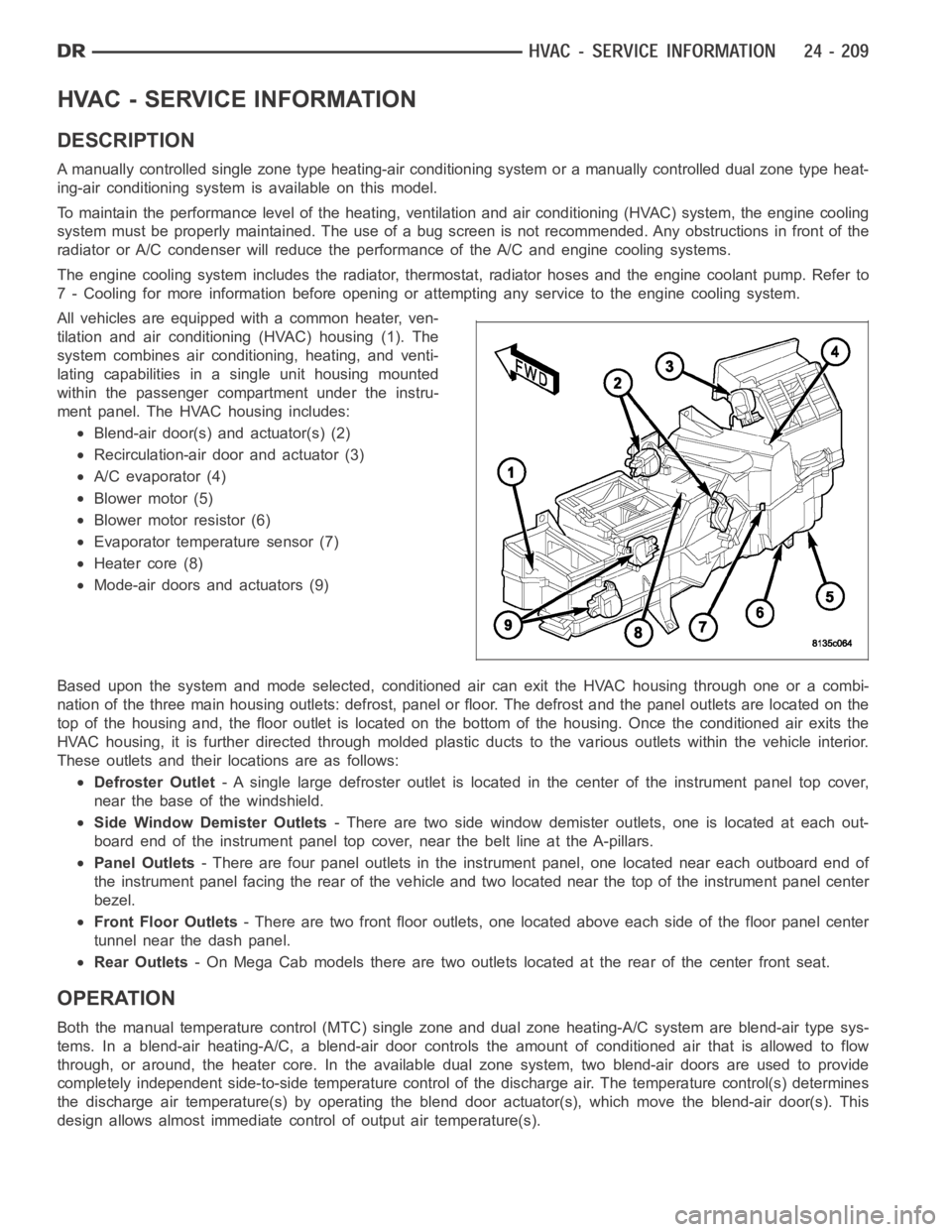
All vehicles are equipped with a common heater, ven-
tilation and air conditioning (HVAC) housing (1). The
system combines air conditioning, heating, and venti-
lating capabilities in a single unit housing mounted
within the passenger compartment under the instru-
ment panel. The HVAC housing includes:
Blend-air door(s) and actuator(s) (2)
Recirculation-air door and actuator (3)
A/C evaporator (4)
Blower motor (5)
Blower motor resistor (6)
Evaporator temperature sensor (7)
Heater core (8)
Mode-air doors and actuators (9)
Based upon the system and mode selected, conditioned air can exit the HVAC housing through one or a combi-
nation of the three main housing outlets: defrost, panel or floor. The defrost and the panel outlets are located on the
top of the housing and, the floor outlet is located on the bottom of the housing. Once the conditioned air exits the
HVAC housing, it is further directed through molded plastic ducts to the various outlets within the vehicle interior.
These outlets and their locations are as follows:
Defroster Outlet- A single large defroster outlet is located in the center of the instrumentpanel top cover,
near the base of the windshield.
Side Window Demister Outlets- There are two side window demister outlets, one is located at each out-
board end of the instrument panel top cover, near the belt line at the A-pillars.
Panel Outlets- There are four panel outlets in the instrument panel, one located near each outboard end of
the instrument panel facing the rear of the vehicle and two located near thetop of the instrument panel center
bezel.
Front Floor Outlets- There are two front floor outlets, one located above each side of the floorpanel center
tunnel near the dash panel.
Rear Outlets- On Mega Cab models there are two outlets located at the rear of the center front seat.
OPERATION
Both the manual temperature control (MTC) single zone and dual zone heating-A/C system are blend-air type sys-
tems. In a blend-air heating-A/C, a blend-air door controls the amount of conditioned air that is allowed to flow
through, or around, the heater core.In the available dual zone system, twoblend-air doors are used to provide
completely independent side-to-side temperature control of the discharge air. The temperature control(s) determines
the discharge air temperature(s) by operating the blend door actuator(s), which move the blend-air door(s). This
design allows almost immediate control of output air temperature(s).
Page 5053 of 5267
ACTUATOR DTC DETECTION TEST — DUAL-ZONE
The Actuator DTC Detection Test:
is actuated with a scan tool.
clears all actuator related DTCs when the test is actuated.
supplements the continuous diagnostics on the actuator drive system.
monitors for shorted actuator circuits allowing service to easily diagnose and troubleshoot up to three simul-
taneous shorts. Shorted actuator circuit faults (XXX Control Circuit High or XXX Control Circuit Low) will only
display after running the Actuator DTC Detection Test.
After repairing each DTC, cycle the ignition switch, and then run the Actuator DTC Detection Test again to ensure
that no new DTCs exist. If multiple DTCs are present, beginning with the passenger blend door, diagnose and repair
all short high faults and then short low faults. When the test returns passed, clear all faults and run the Actuator
Calibration function as a final check of system health.
ACTUATOR DTC DETECTION TEST — SINGLE-ZONE
The Actuator DTC Detection Test:
is actuated with a scan tool.
clears all actuator related DTCs when the test is actuated.
supplements the continuous diagnostics on the actuator drive system.
monitors for shorted actuator circuits allowing service to easily diagnose and troubleshoot up to three simul-
taneous shorts. Shorted actuator circuit faults (XXX Control Circuit High or XXX Control Circuit Low) will only
display after running the Actuator DTC Detection Test.
After repairing each DTC, cycle the ignition switch, and then run the Actuator DTC Detection Test again to ensure
that no new DTCs exist. If multiple DTCs are present, beginning with the common circuit, diagnose and repair all
short high faults and then short low faults. When the test returns passed, clear all faults and run the Actuator Cal-
ibration function as a final check of system health.
A/C PERFORMANCE
The A/C system is designed to provide the passenger compartment with low temperature and low humidity air. The
A/C evaporator, located in the HVAC housing is cooled to temperatures nearthe freezing point. As warm damp air
passes over the fins of the A/C evaporator, the air transfers its heat to therefrigerant in the evaporator coils and the
moisture in the air condenses on the evaporator fins. During periods of high heat and humidity, an A/C system will
be more effective in the Recirculation mode (max-A/C). With the system in the Recirculation mode, only air from the
passenger compartment passes through the A/C evaporator. As the passenger compartment air dehumidifies, the
A/C system performance levels rise.
Humidity has an important bearing on the temperature of the air delivered to the interior of the vehicle. It is impor-
tant to understand the effect that humidity has on the performance of the A/C system. When humidity is high, the
A/C evaporator has to perform a double duty. It must lower the air temperature, and it must lower the temperature
of the moisture in the air that condenses on the evaporator fins. Condensing the moisture in the air transfers heat
energy into the evaporator fins and coils. This reduces the amount of heat the A/C evaporator can absorb from the
air. High humidity greatly reduces the ability of the A/C evaporator to lower the temperature of the air.
However, evaporator capacity used to reduce the amount of moisture in the air is not wasted. Wringing some of the
moisture out of the air entering the vehicle adds to the comfort of the passengers. Although, an owner may expect
too much from their A/C system on humid days. A performance test is the best way to determine whether the sys-
tem is performing up to design standards. This test also provides valuableclues as to the possible cause of trouble
with the A/C system. The ambient air temperature in the location where the vehicle will be tested must be a mini-
mum of 21° C (70° F) for this test.
A/C PERFORMANCE TEST
WARNING: Refer to the applicable warnings and cautions for this system before performing the following
operation (Refer to 24 - HEATING & AIR CONDITIONING/PLUMBING - WARNINGS) and (Refer to 24 - HEAT-
ING & AIR CONDITIONING/PLUMBING - CAUTIONS). Failure to follow the warnings and cautions could result
in possible personal injury or death.
Page 5054 of 5267
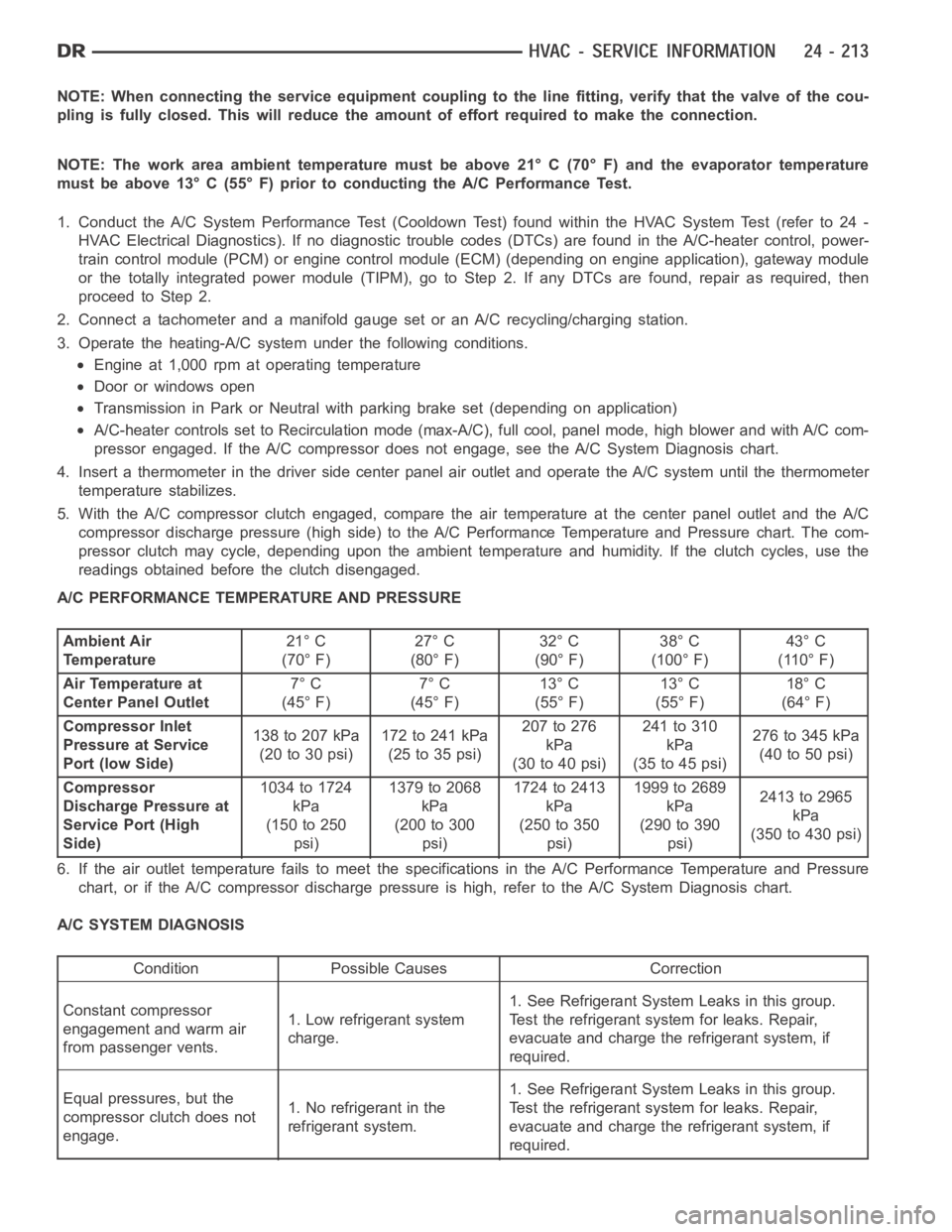
NOTE: When connecting the service equipment coupling to the line fitting,verify that the valve of the cou-
pling is fully closed. This will reduce the amount of effort required to make the connection.
NOTE: The work area ambient temperature must be above 21° C (70° F) and the evaporator temperature
must be above 13° C (55° F) prior to conducting the A/C Performance Test.
1. Conduct the A/C System Performance Test (Cooldown Test) found within the HVAC System Test (refer to 24 -
HVAC Electrical Diagnostics). If no diagnostic trouble codes (DTCs) are found in the A/C-heater control, power-
train control module (PCM) or engine control module (ECM) (depending on engine application), gateway module
or the totally integrated power module (TIPM), go to Step 2. If any DTCs are found, repair as required, then
proceedtoStep2.
2. Connect a tachometer and a manifold gauge set or an A/C recycling/charging station.
3. Operate the heating-A/C system under the following conditions.
Engine at 1,000 rpm at operating temperature
Door or windows open
Transmission in Park or Neutral with parking brake set (depending on application)
A/C-heater controls set to Recirculation mode (max-A/C), full cool, panel mode, high blower and with A/C com-
pressor engaged. If the A/C compressor does not engage, see the A/C System Diagnosis chart.
4. Insert a thermometer in the driver side center panel air outlet and operate the A/C system until the thermometer
temperature stabilizes.
5. With the A/C compressor clutch engaged, compare the air temperature at the center panel outlet and the A/C
compressor discharge pressure (high side) to the A/C Performance Temperature and Pressure chart. The com-
pressor clutch may cycle, depending upon the ambient temperature and humidity. If the clutch cycles, use the
readings obtained before the clutch disengaged.
A/C PERFORMANCE TEMPERATURE AND PRESSURE
Ambient Air
Temperature21° C
(70° F)27° C
(80° F)32° C
(90° F)38° C
(100° F)43° C
(110° F)
Air Temperature at
Center Panel Outlet7° C
(45° F)7° C
(45° F)13° C
(55° F)13° C
(55° F)18° C
(64° F)
Compressor Inlet
Pressure at Service
Port (low Side)138 to 207 kPa
(20to30psi)172to241kPa
(25to35psi)207 to 276
kPa
(30to40psi)241 to 310
kPa
(35to45psi)276to345kPa
(40to50psi)
Compressor
Discharge Pressure at
Service Port (High
Side)1034 to 1724
kPa
(150 to 250
psi)1379to2068
kPa
(200 to 300
psi)1724to2413
kPa
(250 to 350
psi)1999 to 2689
kPa
(290 to 390
psi)2413to2965
kPa
(350 to 430 psi)
6. If the air outlet temperature fails to meet the specifications in the A/CPerformance Temperature and Pressure
chart, or if the A/C compressor discharge pressure is high, refer to the A/CSystem Diagnosis chart.
A/C SYSTEM DIAGNOSIS
Condition Possible Causes Correction
Constant compressor
engagement and warm air
from passenger vents.1. Low refrigerant system
charge.1. See Refrigerant System Leaks in this group.
Test the refrigerant system for leaks. Repair,
evacuate and charge the refrigerant system, if
required.
Equal pressures, but the
compressor clutch does not
engage.1. No refrigerant in the
refrigerant system.1. See Refrigerant System Leaks in this group.
Test the refrigerant system for leaks. Repair,
evacuate and charge the refrigerant system, if
required.
Page 5057 of 5267
Improper heater hose routing.
Plugged heater hoses or supply and return ports at the cooling system connections.
Plugged heater core.
If proper coolant flow through the cooling system is verified, and heater outlet air temperature is low, a mechanical
problem may exist.
MECHANICAL PROBLEMS
Possible locations or causes of insufficient heat due to mechanical problems are as follows:
Obstructed cowl air intake.
Obstructed heater system outlets.
Blend-air door(s) or actuator(s) not functioning properly.
Faulty blower motor system
Faulty A/C-heater control
TEMPERATURE CONTROL
If the heater outlet air temperature cannot be adjusted with the temperature control on the A/C-heater control, the
following could require service:
Faulty A/C-heater control.
Faulty blend door actuator(s).
Faulty, obstructed or improperly installed blend-air door.
Faulty related wiring harness or connectors.
Improper engine coolant temperature.
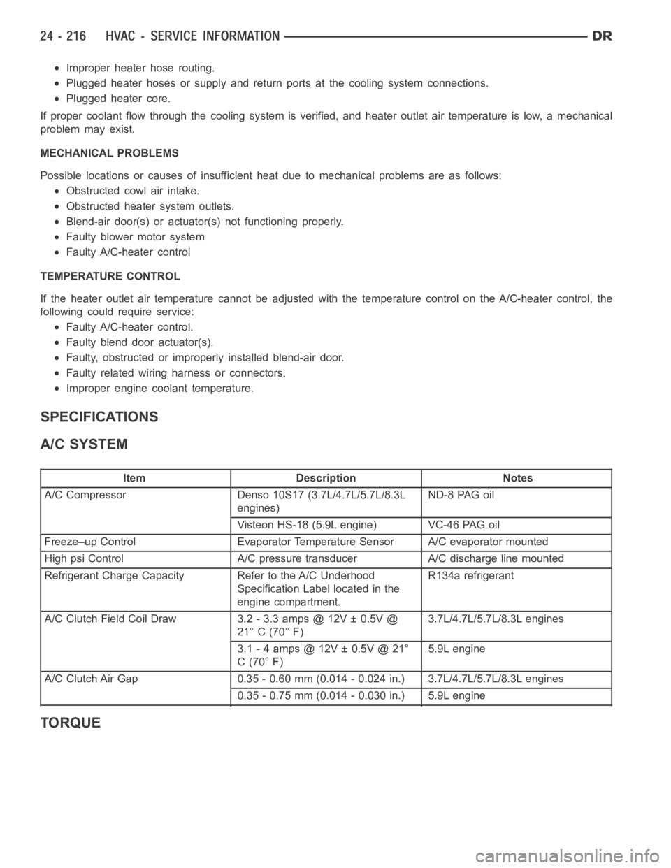
SPECIFICATIONS
A/C SYSTEM
Item Description Notes
A/C Compressor Denso 10S17 (3.7L/4.7L/5.7L/8.3L
engines)ND-8 PAG oil
Visteon HS-18 (5.9L engine) VC-46 PAG oil
Freeze–up Control Evaporator Temperature Sensor A/C evaporator mounted
High psi Control A/C pressure transducer A/C discharge line mounted
Refrigerant Charge Capacity Refer to the A/C Underhood
Specification Label located in the
engine compartment.R134a refrigerant
A/C Clutch Field Coil Draw 3.2 - 3.3 amps @ 12V ± 0.5V @
21° C (70° F)3.7L/4.7L/5.7L/8.3L engines
3.1 - 4 amps @ 12V ± 0.5V @ 21°
C(70°F)5.9L engine
A/C Clutch Air Gap 0.35 - 0.60 mm (0.014 - 0.024 in.) 3.7L/4.7L/5.7L/8.3L engines
0.35 - 0.75 mm (0.014 - 0.030 in.) 5.9L engine
TORQUE