Page 5024 of 5267
Diagnose and repair the other DTC(s). If multiple DTCs are present, beginning with the passenger blend
door, diagnose and repair all short high DTCs and then all short low DTCs. Refer to the Table of Con-
tents in this Section for a complete list of HVAC related symptoms.
No, And No DTCs Displayed
Using the wiring diagram as a guide, inspect the wiring and connectors for conditions causing an inter-
mittent short. Repair as necessary.
Perform BODY VERIFICATION TEST – VER 1. (Refer to 8 - ELECTRICAL/ELECTRONIC CONTROL
MODULES - STANDARD PROCEDURE).
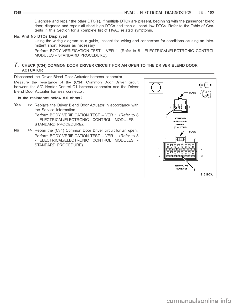
7.CHECK (C34) COMMON DOOR DRIVER CIRCUIT FOR AN OPEN TO THE DRIVER BLEND DOOR
ACTUATOR
Disconnect the Driver Blend Door Actuator harness connector.
Measure the resistance of the (C34) Common Door Driver circuit
between the A/C Heater Control C1 harness connector and the Driver
Blend Door Actuator harness connector.
Is the resistance below 5.0 ohms?
Ye s>>
Replace the Driver Blend Door Actuator in accordance with
the Service Information.
Perform BODY VERIFICATION TEST – VER 1. (Refer to 8
- ELECTRICAL/ELECTRONIC CONTROL MODULES -
STANDARD PROCEDURE).
No>>
Repair the (C34) Common Door Driver circuit for an open.
Perform BODY VERIFICATION TEST – VER 1. (Refer to 8
- ELECTRICAL/ELECTRONIC CONTROL MODULES -
STANDARD PROCEDURE).
Page 5025 of 5267
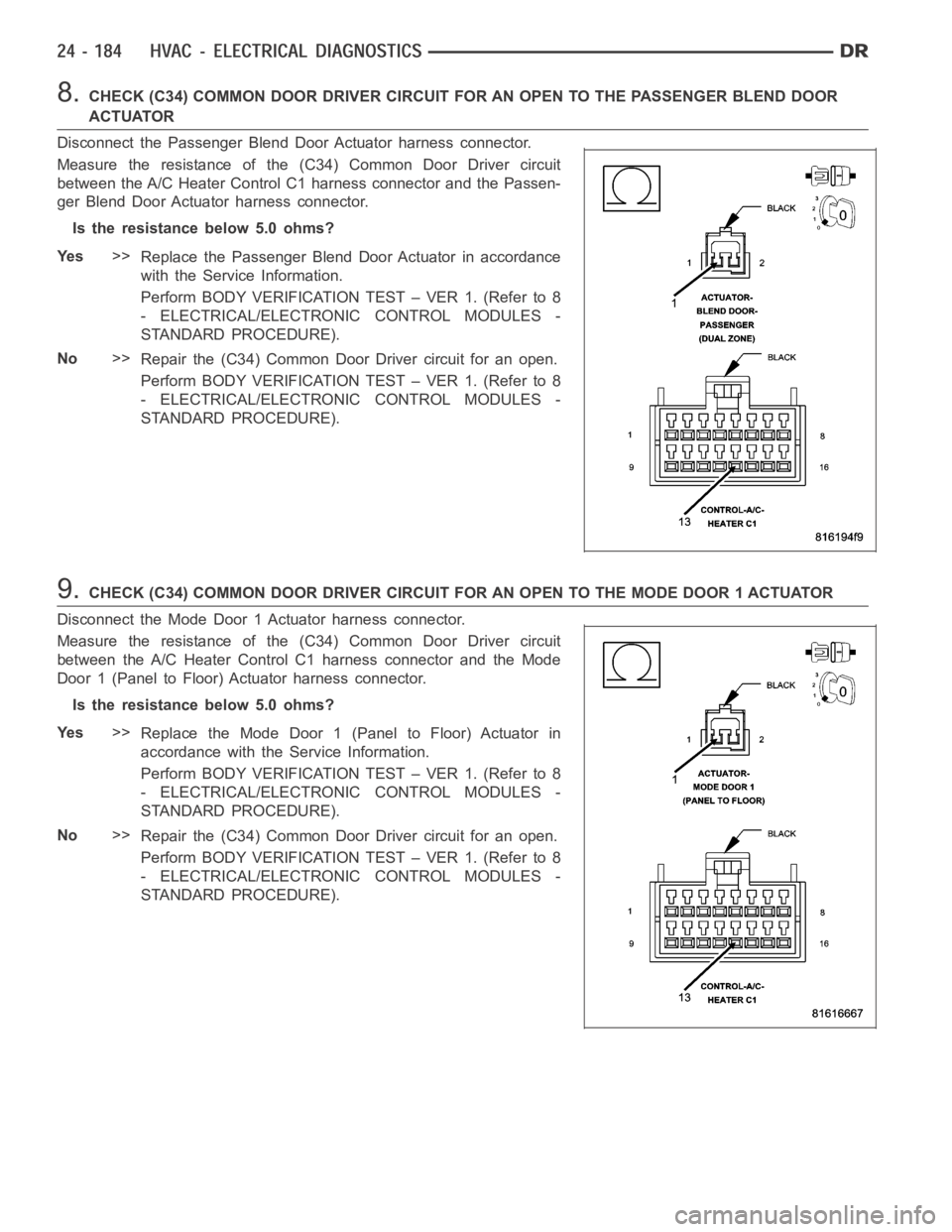
8.CHECK (C34) COMMON DOOR DRIVER CIRCUIT FOR AN OPEN TO THE PASSENGER BLEND DOOR
ACTUATOR
Disconnect the Passenger Blend Door Actuator harness connector.
Measure the resistance of the (C34) Common Door Driver circuit
between the A/C Heater Control C1 harness connector and the Passen-
ger Blend Door Actuator harness connector.
Is the resistance below 5.0 ohms?
Ye s>>
Replace the Passenger Blend Door Actuator in accordance
with the Service Information.
Perform BODY VERIFICATION TEST – VER 1. (Refer to 8
- ELECTRICAL/ELECTRONIC CONTROL MODULES -
STANDARD PROCEDURE).
No>>
Repair the (C34) Common Door Driver circuit for an open.
Perform BODY VERIFICATION TEST – VER 1. (Refer to 8
- ELECTRICAL/ELECTRONIC CONTROL MODULES -
STANDARD PROCEDURE).
9.CHECK (C34) COMMON DOOR DRIVER CIRCUIT FOR AN OPEN TO THE MODE DOOR 1 ACTUATOR
Disconnect the Mode Door 1 Actuator harness connector.
Measure the resistance of the (C34) Common Door Driver circuit
between the A/C Heater Control C1 harness connector and the Mode
Door 1 (Panel to Floor) Actuator harness connector.
Is the resistance below 5.0 ohms?
Ye s>>
Replace the Mode Door 1 (Panel to Floor) Actuator in
accordance with the Service Information.
Perform BODY VERIFICATION TEST – VER 1. (Refer to 8
- ELECTRICAL/ELECTRONIC CONTROL MODULES -
STANDARD PROCEDURE).
No>>
Repair the (C34) Common Door Driver circuit for an open.
Perform BODY VERIFICATION TEST – VER 1. (Refer to 8
- ELECTRICAL/ELECTRONIC CONTROL MODULES -
STANDARD PROCEDURE).
Page 5026 of 5267
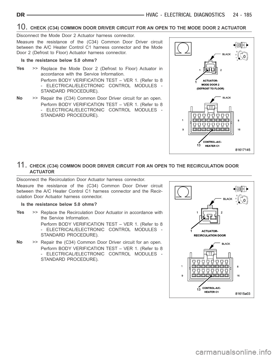
10.CHECK (C34) COMMON DOOR DRIVER CIRCUIT FOR AN OPEN TO THE MODE DOOR 2 ACTUATOR
Disconnect the Mode Door 2 Actuator harness connector.
Measure the resistance of the (C34) Common Door Driver circuit
between the A/C Heater Control C1 harness connector and the Mode
Door 2 (Defrost to Floor) Actuator harness connector.
Is the resistance below 5.0 ohms?
Ye s>>
Replace the Mode Door 2 (Defrost to Floor) Actuator in
accordance with the Service Information.
Perform BODY VERIFICATION TEST – VER 1. (Refer to 8
- ELECTRICAL/ELECTRONIC CONTROL MODULES -
STANDARD PROCEDURE).
No>>
Repair the (C34) Common Door Driver circuit for an open.
Perform BODY VERIFICATION TEST – VER 1. (Refer to 8
- ELECTRICAL/ELECTRONIC CONTROL MODULES -
STANDARD PROCEDURE).
11 .CHECK (C34) COMMON DOOR DRIVER CIRCUIT FOR AN OPEN TO THE RECIRCULATION DOOR
ACTUATOR
Disconnect the Recirculation Door Actuator harness connector.
Measure the resistance of the (C34) Common Door Driver circuit
between the A/C Heater Control C1 harness connector and the Recir-
culation Door Actuator harness connector.
Is the resistance below 5.0 ohms?
Ye s>>
Replace the Recirculation Door Actuator in accordance with
the Service Information.
Perform BODY VERIFICATION TEST – VER 1. (Refer to 8
- ELECTRICAL/ELECTRONIC CONTROL MODULES -
STANDARD PROCEDURE).
No>>
Repair the (C34) Common Door Driver circuit for an open.
Perform BODY VERIFICATION TEST – VER 1. (Refer to 8
- ELECTRICAL/ELECTRONIC CONTROL MODULES -
STANDARD PROCEDURE).
Page 5030 of 5267
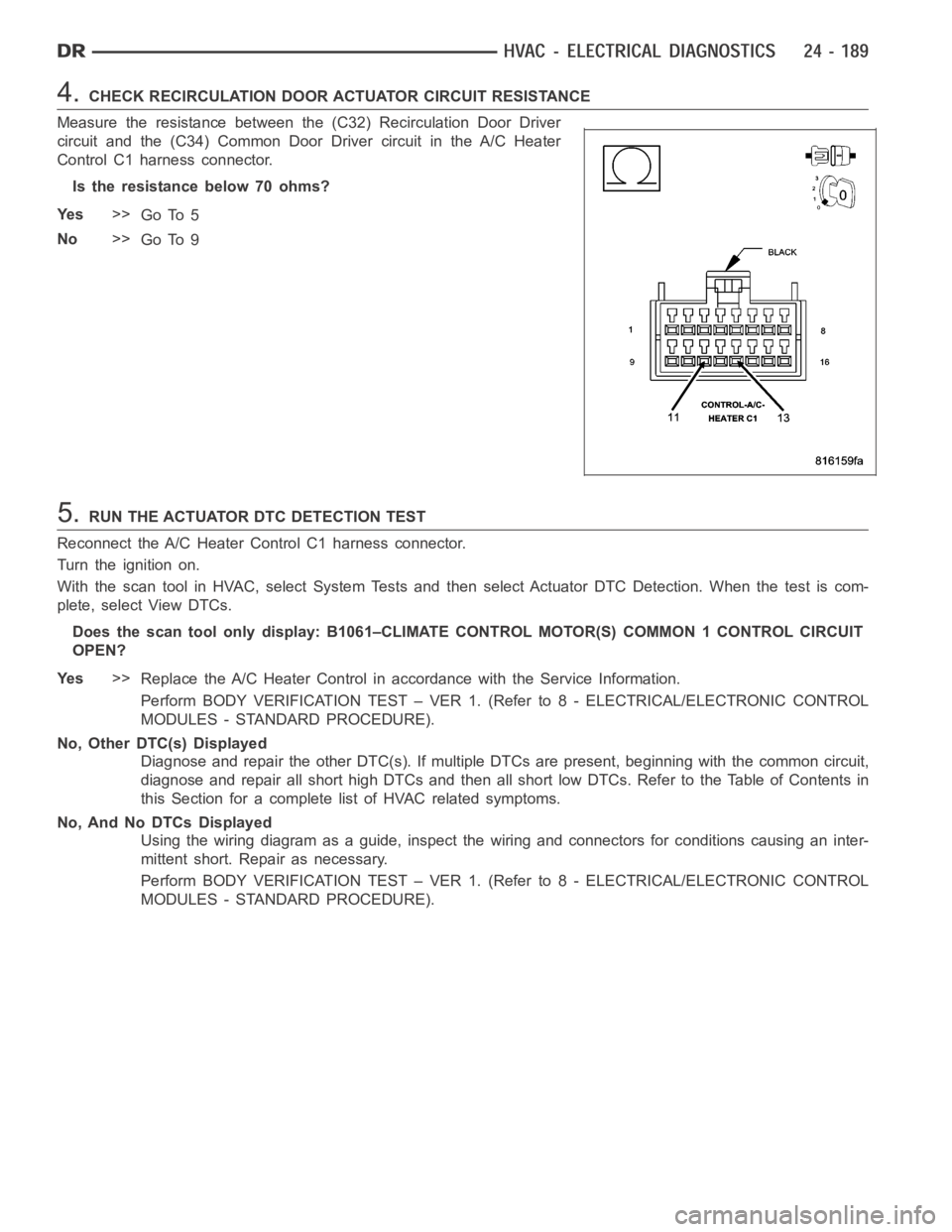
4.CHECK RECIRCULATION DOOR ACTUATOR CIRCUIT RESISTANCE
Measure the resistance between the (C32) Recirculation Door Driver
circuit and the (C34) Common Door Driver circuit in the A/C Heater
Control C1 harness connector.
Is the resistance below 70 ohms?
Ye s>>
Go To 5
No>>
Go To 9
5.RUN THE ACTUATOR DTC DETECTION TEST
Reconnect the A/C Heater Control C1 harness connector.
Turn the ignition on.
With the scan tool in HVAC, select System Tests and then select Actuator DTCDetection. When the test is com-
plete, select View DTCs.
Does the scan tool only display: B1061–CLIMATE CONTROL MOTOR(S) COMMON 1 CONTROL CIRCUIT
OPEN?
Ye s>>
Replace the A/C Heater Control in accordance with the Service Information.
Perform BODY VERIFICATION TEST – VER 1. (Refer to 8 - ELECTRICAL/ELECTRONIC CONTROL
MODULES - STANDARD PROCEDURE).
No, Other DTC(s) Displayed
Diagnose and repair the other DTC(s). If multiple DTCs are present, beginning with the common circuit,
diagnose and repair all short high DTCs and then all short low DTCs. Refer tothe Table of Contents in
this Section for a complete list of HVAC related symptoms.
No, And No DTCs Displayed
Using the wiring diagram as a guide, inspect the wiring and connectors for conditions causing an inter-
mittent short. Repair as necessary.
Perform BODY VERIFICATION TEST – VER 1. (Refer to 8 - ELECTRICAL/ELECTRONIC CONTROL
MODULES - STANDARD PROCEDURE).
Page 5031 of 5267
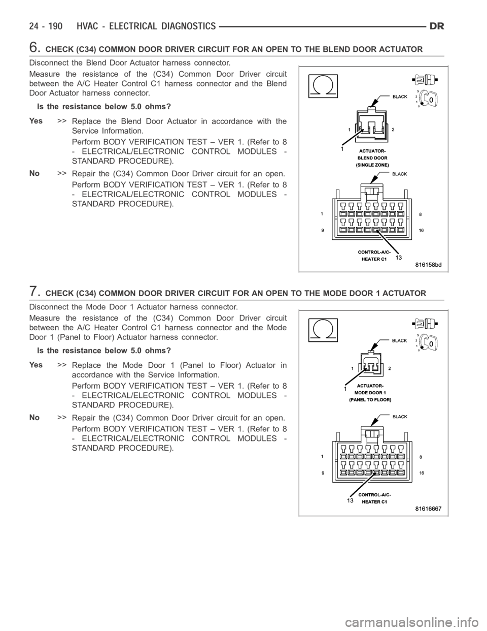
6.CHECK (C34) COMMON DOOR DRIVER CIRCUIT FOR AN OPEN TO THE BLEND DOOR ACTUATOR
Disconnect the Blend Door Actuator harness connector.
Measure the resistance of the (C34) Common Door Driver circuit
between the A/C Heater Control C1 harness connector and the Blend
Door Actuator harness connector.
Is the resistance below 5.0 ohms?
Ye s>>
Replace the Blend Door Actuator in accordance with the
Service Information.
Perform BODY VERIFICATION TEST – VER 1. (Refer to 8
- ELECTRICAL/ELECTRONIC CONTROL MODULES -
STANDARD PROCEDURE).
No>>
Repair the (C34) Common Door Driver circuit for an open.
Perform BODY VERIFICATION TEST – VER 1. (Refer to 8
- ELECTRICAL/ELECTRONIC CONTROL MODULES -
STANDARD PROCEDURE).
7.CHECK (C34) COMMON DOOR DRIVER CIRCUIT FOR AN OPEN TO THE MODE DOOR 1 ACTUATOR
Disconnect the Mode Door 1 Actuator harness connector.
Measure the resistance of the (C34) Common Door Driver circuit
between the A/C Heater Control C1 harness connector and the Mode
Door 1 (Panel to Floor) Actuator harness connector.
Is the resistance below 5.0 ohms?
Ye s>>
Replace the Mode Door 1 (Panel to Floor) Actuator in
accordance with the Service Information.
Perform BODY VERIFICATION TEST – VER 1. (Refer to 8
- ELECTRICAL/ELECTRONIC CONTROL MODULES -
STANDARD PROCEDURE).
No>>
Repair the (C34) Common Door Driver circuit for an open.
Perform BODY VERIFICATION TEST – VER 1. (Refer to 8
- ELECTRICAL/ELECTRONIC CONTROL MODULES -
STANDARD PROCEDURE).
Page 5032 of 5267
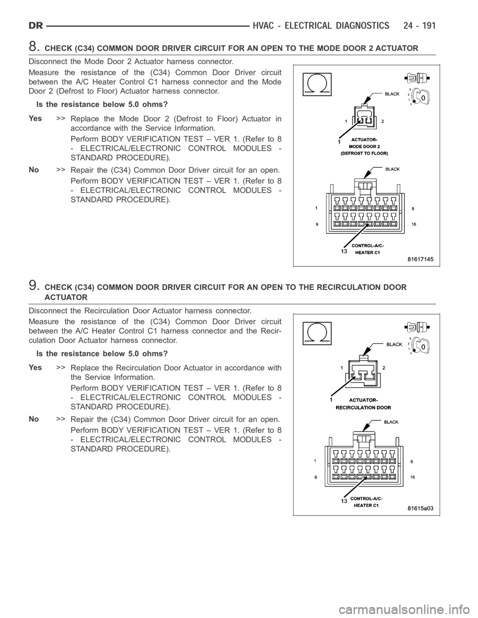
8.CHECK (C34) COMMON DOOR DRIVER CIRCUIT FOR AN OPEN TO THE MODE DOOR 2 ACTUATOR
Disconnect the Mode Door 2 Actuator harness connector.
Measure the resistance of the (C34) Common Door Driver circuit
between the A/C Heater Control C1 harness connector and the Mode
Door 2 (Defrost to Floor) Actuator harness connector.
Is the resistance below 5.0 ohms?
Ye s>>
Replace the Mode Door 2 (Defrost to Floor) Actuator in
accordance with the Service Information.
Perform BODY VERIFICATION TEST – VER 1. (Refer to 8
- ELECTRICAL/ELECTRONIC CONTROL MODULES -
STANDARD PROCEDURE).
No>>
Repair the (C34) Common Door Driver circuit for an open.
Perform BODY VERIFICATION TEST – VER 1. (Refer to 8
- ELECTRICAL/ELECTRONIC CONTROL MODULES -
STANDARD PROCEDURE).
9.CHECK (C34) COMMON DOOR DRIVER CIRCUIT FOR AN OPEN TO THE RECIRCULATION DOOR
ACTUATOR
Disconnect the Recirculation Door Actuator harness connector.
Measure the resistance of the (C34) Common Door Driver circuit
between the A/C Heater Control C1 harness connector and the Recir-
culation Door Actuator harness connector.
Is the resistance below 5.0 ohms?
Ye s>>
Replace the Recirculation Door Actuator in accordance with
the Service Information.
Perform BODY VERIFICATION TEST – VER 1. (Refer to 8
- ELECTRICAL/ELECTRONIC CONTROL MODULES -
STANDARD PROCEDURE).
No>>
Repair the (C34) Common Door Driver circuit for an open.
Perform BODY VERIFICATION TEST – VER 1. (Refer to 8
- ELECTRICAL/ELECTRONIC CONTROL MODULES -
STANDARD PROCEDURE).
Page 5034 of 5267
2.CHECK FOR DTCs IN THE A/C HEATER CONTROL MODULE
Turn the ignition on.
With the scan tool, read HVAC DTCs.
Excluding B1079–Climate Control Cool Down Test Excessive Time, are any DTCs present in the A/C
Heater Control Module?
Ye s>>
Diagnose and Repair the DTC(s). Refer to the Table of Contents in this Section for a complete list of
HVAC related symptoms. Rerun the Cooldown Test after the repair is complete.
Perform BODY VERIFICATION TEST – VER 1. (Refer to 8 - ELECTRICAL/ELECTRONIC CONTROL
MODULES - STANDARD PROCEDURE).
No>>
Go To 3
3.CHECK FOR DTCs IN THE TIPM
With the scan tool, read TIPM DTCs.
Are any DTCs present in the TIPM?
Ye s>>
Diagnose and Repair the DTC(s). Rerun the Cooldown Test after the repair iscomplete.
Perform BODY VERIFICATION TEST – VER 1. (Refer to 8 - ELECTRICAL/ELECTRONIC CONTROL
MODULES - STANDARD PROCEDURE).
No>>
Go To 4
4.CHECK FOR DTCs IN THE PCM / ECM
With the scan tool, read PCM / ECM DTCs.
Are any DTCs present in the PCM / ECM?
Ye s>>
Diagnose and repair the DTC(s). (Refer to 9 - ENGINE - DIAGNOSIS AND TESTING) for the diagnostic
procedures. Rerun the Cooldown Test after the repair is complete.
Perform BODY VERIFICATION TEST – VER 1. (Refer to 8 - ELECTRICAL/ELECTRONIC CONTROL
MODULES - STANDARD PROCEDURE).
No>>
Refer to the Service Information for additional Cooldown Test related diagnostic information and testing
procedures. Rerun the Cooldown Test after the repair is complete.
Perform BODY VERIFICATION TEST – VER 1. (Refer to 8 - ELECTRICAL/ELECTRONIC CONTROL
MODULES - STANDARD PROCEDURE).
Page 5035 of 5267
B2214–(HVAC) CLIMATE CONTROL INTERNAL
For a complete wiring diagramRefer to Section 8W.
When Monitored:
With the ignition on.
Set Condition:
If the A/C Heater Control has an internal fault. This DTC has a maturing timeof 5 seconds and a de-maturing
time of 10 seconds. If the DTC’s status changes from active to stored it willstay in memory for 100 ignition
cycles.
Possible Causes
A/C HEATER CONTROL
NOTE: This DTC must be active for the results of this test to be valid. Do not perform this test if this DTC
is stored. Refer to either HVAC System Test (ATC) or to HVAC System Test (MTC) for stored DTC test pro-
cedures.
Diagnostic Test
1.REPLACE THE A/C HEATER CONTROL
Repair
Replace the A/C Heater Control in accordance with the Service Information.
Perform BODY VERIFICATION TEST – VER 1. (Refer to 8 - ELECTRICAL/ELECTRONIC CONTROL
MODULES - STANDARD PROCEDURE).