Page 1 of 5267
3.PCM
NOTE: Before continuing, check the PCM harness connector terminals for corrosion, damage, or terminal
push out. Repair as necessary.
Using the schematics as a guide, inspect the wire harness and connectors. Pay particular attention to all Power and
Ground circuits.
Were there any problems found?
Ye s>>
Repair as necessary.
Perform the POWERTRAIN VERIFICATION TEST. (Refer to 9 - ENGINE - STANDARD PROCEDURE)
No>>
Replace and program the Powertrain Control Module per Service Information.
Perform the POWERTRAIN VERIFICATION TEST. (Refer to 9 - ENGINE - STANDARD PROCEDURE)
Page 5 of 5267

5.A/C CLUTCH CONTROL OPERATION FROM THE PCM
Turn the ignition off.
Connect the C3 PCM harness connector.
Ignition on, engine not running.
Using the scan tool in the PCM, actuate the A/C Clutch.
With a 12-volt test light connected to ground, probe the (C13) A/C
Clutch Control circuit in the TIPM C2 harness connector.
Does the test light illuminate brightly and flash on an off?
Ye s>>
NOTE: Before continuing, check the TIPM harness connector ter-
minals for corrosion, damage, or terminal push out. Repair as nec-
essary.
If OK, replace the TIPM in accordance with the Service Information.
No>>
Go To 6
6.PCM
NOTE: Before continuing, check the PCM harness connector terminals for corrosion, damage, or terminal
push out. Repair as necessary.
Using the schematics as a guide, inspect the wire harness and connectors. Pay particular attention to all Power and
Ground circuits.
Were there any problems found?
Ye s>>
Repair as necessary.
Perform the POWERTRAIN VERIFICATION TEST. (Refer to 9 - ENGINE - STANDARD PROCEDURE)
No>>
Replace and program the Powertrain Control Module per Service Information.
Perform the POWERTRAIN VERIFICATION TEST. (Refer to 9 - ENGINE - STANDARD PROCEDURE)
Page 8 of 5267

3.CMP SENSOR
Turn the ignition off.
Reconnect all the previously disconnected Sensors except for the CMP
Sensor harness connector.
Ignition on, engine not running.
Measure the voltage on the (F856) Auxiliary 5-volt Supply circuit in the
CMP Sensor harness connector.
Is the voltage below 4.5 volts?
Ye s>>
Go To 4
No>>
Replace the Cam Position Sensor.
Perform the POWERTRAIN VERIFICATION TEST. (Refer to
9 - ENGINE - STANDARD PROCEDURE)
4.5-VOLT SENSOR SHORTED TO GROUND
Measure the voltage on the (F856) Auxiliary 5-volt Supply circuit at the
CMP Sensor harness connector.
CAUTION: You must Turn the Ignition OFF when disconnecting any
of the Sensor harness connectors and Turn the Ignition On to
check the voltage readings.
While monitoring the voltage, disconnect each Sensor harness connec-
tor that shares the (F856) Auxiliary 5-volt Supply circuit, one at a time.
Does the voltage increase above 4.5 volts when disconnecting
any of the Sensor harness connectors?
Ye s>>
Replace the Sensor that causes the (F856) Auxiliary 5-volt
Supply circuit voltage to increase when disconnected.
Perform the POWERTRAIN VERIFICATION TEST. (Refer to
9 - ENGINE - STANDARD PROCEDURE)
No>>
Go To 5
5.PCM
NOTE: Before continuing, check the PCM harness connector terminals for corrosion, damage, or terminal
push out. Repair as necessary.
Using the schematics as a guide, inspect the wire harness and connectors. Pay particular attention to all Power and
Ground circuits.
Were there any problems found?
Ye s>>
Repair as necessary.
Perform the POWERTRAIN VERIFICATION TEST. (Refer to 9 - ENGINE - STANDARD PROCEDURE)
No>>
Replace and program the Powertrain Control Module per Service Information.
Perform the POWERTRAIN VERIFICATION TEST. (Refer to 9 - ENGINE - STANDARD PROCEDURE)
Page 11 of 5267
3.PCM
NOTE: Before continuing, check the PCM harness connector terminals for corrosion, damage, or terminal
push out. Repair as necessary.
Using the schematics as a guide, inspect the wire harness and connectors. Pay particular attention to all Power and
Ground circuits.
Were there any problems found?
Ye s>>
Repair as necessary.
Perform the POWERTRAIN VERIFICATION TEST. (Refer to 9 - ENGINE - STANDARD PROCEDURE)
No>>
Replace and program the Powertrain Control Module per Service Information.
Perform the POWERTRAIN VERIFICATION TEST. (Refer to 9 - ENGINE - STANDARD PROCEDURE)
Page 15 of 5267
6.PCM
NOTE: Before continuing, check the PCM harness connector terminals for corrosion, damage, or terminal
push out. Repair as necessary.
Using the schematics as a guide, inspect the wire harness and connectors. Pay particular attention to all Power and
Ground circuits.
Were there any problems found?
Ye s>>
Repair as necessary.
Perform the POWERTRAIN VERIFICATION TEST. (Refer to 9 - ENGINE - STANDARD PROCEDURE)
No>>
Replace and program the Powertrain Control Module per Service Information.
Perform the POWERTRAIN VERIFICATION TEST. (Refer to 9 - ENGINE - STANDARD PROCEDURE)
Page 20 of 5267
7.PCM
NOTE: Before continuing, check the PCM harness connector terminals for corrosion, damage, or terminal
push out. Repair as necessary.
Using the schematics as a guide, inspect the wire harness and connectors. Pay particular attention to all Power and
Ground circuits.
Were there any problems found?
Ye s>>
Repair as necessary.
Perform the POWERTRAIN VERIFICATION TEST. (Refer to 9 - ENGINE - STANDARD PROCEDURE)
No>>
Replace and program the Powertrain Control Module per Service Information.
Perform the POWERTRAIN VERIFICATION TEST. (Refer to 9 - ENGINE - STANDARD PROCEDURE)
Page 26 of 5267

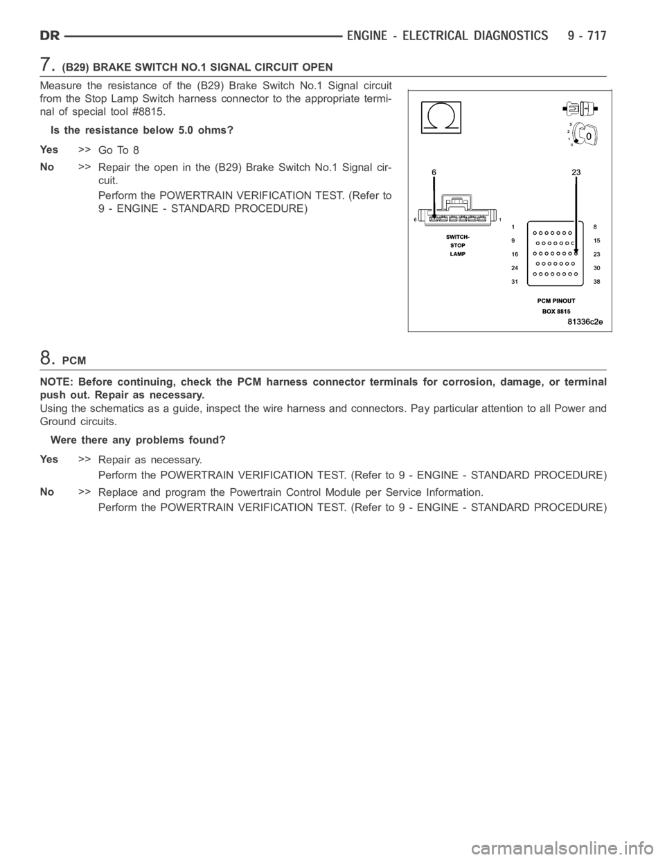
7.(B29) BRAKE SWITCH NO.1 SIGNAL CIRCUIT OPEN
Measure the resistance of the (B29) Brake Switch No.1 Signal circuit
from the Stop Lamp Switch harness connector to the appropriate termi-
nal of special tool #8815.
Is the resistance below 5.0 ohms?
Ye s>>
Go To 8
No>>
Repair the open in the (B29) Brake Switch No.1 Signal cir-
cuit.
Perform the POWERTRAIN VERIFICATION TEST. (Refer to
9 - ENGINE - STANDARD PROCEDURE)
8.PCM
NOTE: Before continuing, check the PCM harness connector terminals for corrosion, damage, or terminal
push out. Repair as necessary.
Using the schematics as a guide, inspect the wire harness and connectors. Pay particular attention to all Power and
Ground circuits.
Were there any problems found?
Ye s>>
Repair as necessary.
Perform the POWERTRAIN VERIFICATION TEST. (Refer to 9 - ENGINE - STANDARD PROCEDURE)
No>>
Replace and program the Powertrain Control Module per Service Information.
Perform the POWERTRAIN VERIFICATION TEST. (Refer to 9 - ENGINE - STANDARD PROCEDURE)
Page 30 of 5267

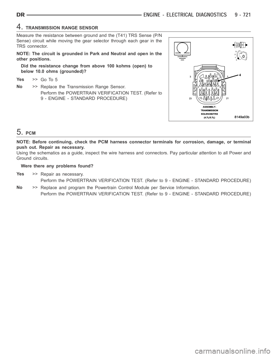
4.TRANSMISSION RANGE SENSOR
Measure the resistance between ground and the (T41) TRS Sense (P/N
Sense) circuit while moving the gear selector through each gear in the
TRS connector.
NOTE: The circuit is grounded in Park and Neutral and open in the
other positions.
Did the resistance change from above 100 kohms (open) to
below 10.0 ohms (grounded)?
Ye s>>
Go To 5
No>>
Replace the Transmission Range Sensor.
Perform the POWERTRAIN VERIFICATION TEST. (Refer to
9 - ENGINE - STANDARD PROCEDURE)
5.PCM
NOTE: Before continuing, check the PCM harness connector terminals for corrosion, damage, or terminal
push out. Repair as necessary.
Using the schematics as a guide, inspect the wire harness and connectors. Pay particular attention to all Power and
Ground circuits.
Were there any problems found?
Ye s>>
Repair as necessary.
Perform the POWERTRAIN VERIFICATION TEST. (Refer to 9 - ENGINE - STANDARD PROCEDURE)
No>>
Replace and program the Powertrain Control Module per Service Information.
Perform the POWERTRAIN VERIFICATION TEST. (Refer to 9 - ENGINE - STANDARD PROCEDURE)