2006 DODGE RAM SRT-10 service
[x] Cancel search: servicePage 5086 of 5267
RESISTOR-BLOWER MOTOR
DESCRIPTION
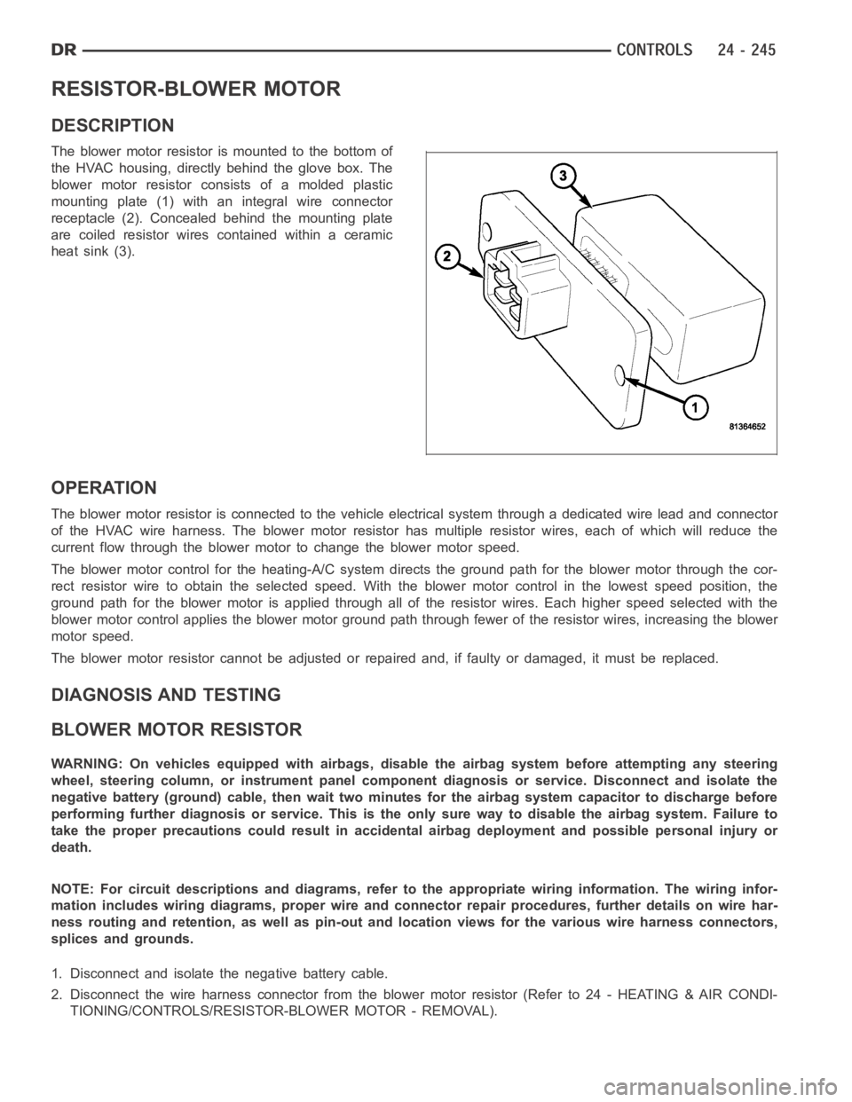
The blower motor resistor is mounted to the bottom of
the HVAC housing, directly behind the glove box. The
blower motor resistor consists of a molded plastic
mounting plate (1) with an integral wire connector
receptacle (2). Concealed behind the mounting plate
are coiled resistor wires contained within a ceramic
heat sink (3).
OPERATION
The blower motor resistor is connected to the vehicle electrical system through a dedicated wire lead and connector
of the HVAC wire harness. The blower motor resistor has multiple resistor wires, each of which will reduce the
current flow through the blower motor to change the blower motor speed.
The blower motor control for the heating-A/C system directs the ground path for the blower motor through the cor-
rect resistor wire to obtain the selected speed. With the blower motor control in the lowest speed position, the
ground path for the blower motor is applied through all of the resistor wires. Each higher speed selected with the
blower motor control applies the blower motor ground path through fewer ofthe resistor wires, increasing the blower
motor speed.
The blower motor resistor cannot be adjusted or repaired and, if faulty or damaged, it must be replaced.
DIAGNOSIS AND TESTING
BLOWER MOTOR RESISTOR
WARNING: On vehicles equipped with airbags, disable the airbag system before attempting any steering
wheel, steering column, or instrument panel component diagnosis or service. Disconnect and isolate the
negative battery (ground) cable, then wait two minutes for the airbag system capacitor to discharge before
performing further diagnosis or service. This is the only sure way to disable the airbag system. Failure to
take the proper precautions could result in accidental airbag deploymentand possible personal injury or
death.
NOTE: For circuit descriptions and diagrams, refer to the appropriate wiring information. The wiring infor-
mation includes wiring diagrams, proper wire and connector repair procedures, further details on wire har-
ness routing and retention, as well as pin-out and location views for the various wire harness connectors,
splices and grounds.
1. Disconnect and isolate the negative battery cable.
2. Disconnect the wire harness connector from the blower motor resistor (Refer to 24 - HEATING & AIR CONDI-
TIONING/CONTROLS/RESISTOR-BLOWER MOTOR - REMOVAL).
Page 5087 of 5267
3. Using an ohmmeter, check for continuity between all of the blower motor resistor terminals. In each case there
should be continuity. If OK, repair the wire harness circuits between the blower motor speed control and the
blower motor resistor or blower motor as required. If not OK, replace the faulty blower motor resistor.
REMOVAL
WARNING: On vehicles equipped with airbags, disable the airbag system before attempting any steering
wheel, steering column, or instrument panel component diagnosis or service. Disconnect and isolate the
battery negative (ground) cable, then wait two minutes for the airbag system capacitor to discharge before
performing further diagnosis or service. This is the only sure way to disable the airbag system. Failure to
take the proper precautions could result in an accidental airbag deployment and possible personal injury or
death.
WARNING: The blower motor resistor may get very hot during normal operation. If the blower motor was
turned on prior to servicing the blower motor resistor, wait five minutes to allow the blower motor resistors
to cool before performing diagnosis or service. Failure to take this precaution can result in possible per-
sonal injury.
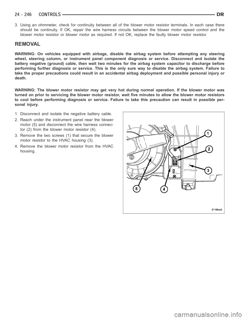
1. Disconnect and isolate the negative battery cable.
2. Reach under the instrument panel near the blower
motor (5) and disconnect the wire harness connec-
tor (2) from the blower motor resistor (4).
3. Remove the two screws (1) that secure the blower
motor resistor to the HVAC housing (3).
4. Remove the blower motor resistor from the HVAC
housing.
Page 5095 of 5267
DUCT-DEFROSTER
REMOVAL
WARNING: On vehicles equipped with airbags, disable the airbag system before attempting any steering
wheel, steering column, or instrument panel component diagnosis or service. Disconnect and isolate the
battery negative (ground) cable, then wait two minutes for the airbag system capacitor to discharge before
performing further diagnosis or service. This is the only sure way to disable the airbag system. Failure to
take the proper precautions could result in accidental airbag deploymentand possible personal injury or
death.
NOTE: Take the proper precautions to protect the instrument panel from cosmetic damage.
1. Remove the instrument panel and place it on a workbench (Refer to 23 - BODY/INSTRUMENT PANEL/INSTRU-
MENT PANEL ASSEMBLY - REMOVAL).
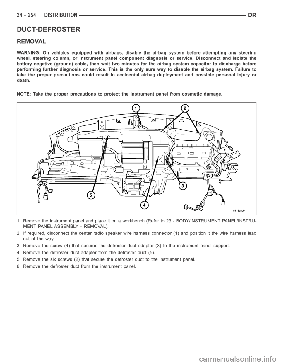
2. If required, disconnect the center radio speaker wire harness connector (1) and position it the wire harness lead
out of the way.
3. Remove the screw (4) that secures the defroster duct adapter (3) to the instrument panel support.
4. Remove the defroster duct adapter from the defroster duct (5).
5. Remove the six screws (2) that secure the defroster duct to the instrument panel.
6. Remove the defroster duct from the instrument panel.
Page 5098 of 5267
DUCT-FLOOR DISTRIBUTION
REMOVAL
WARNING: On vehicles equipped with airbags, disable the airbag system before attempting any steering
wheel, steering column, or instrument panel component diagnosis or service. Disconnect and isolate the
battery negative (ground) cable, then wait two minutes for the airbag system capacitor to discharge before
performing further diagnosis or service. This is the only sure way to disable the airbag system. Failure to
take the proper precautions could result in an accidental airbag deployment and possible personal injury or
death.
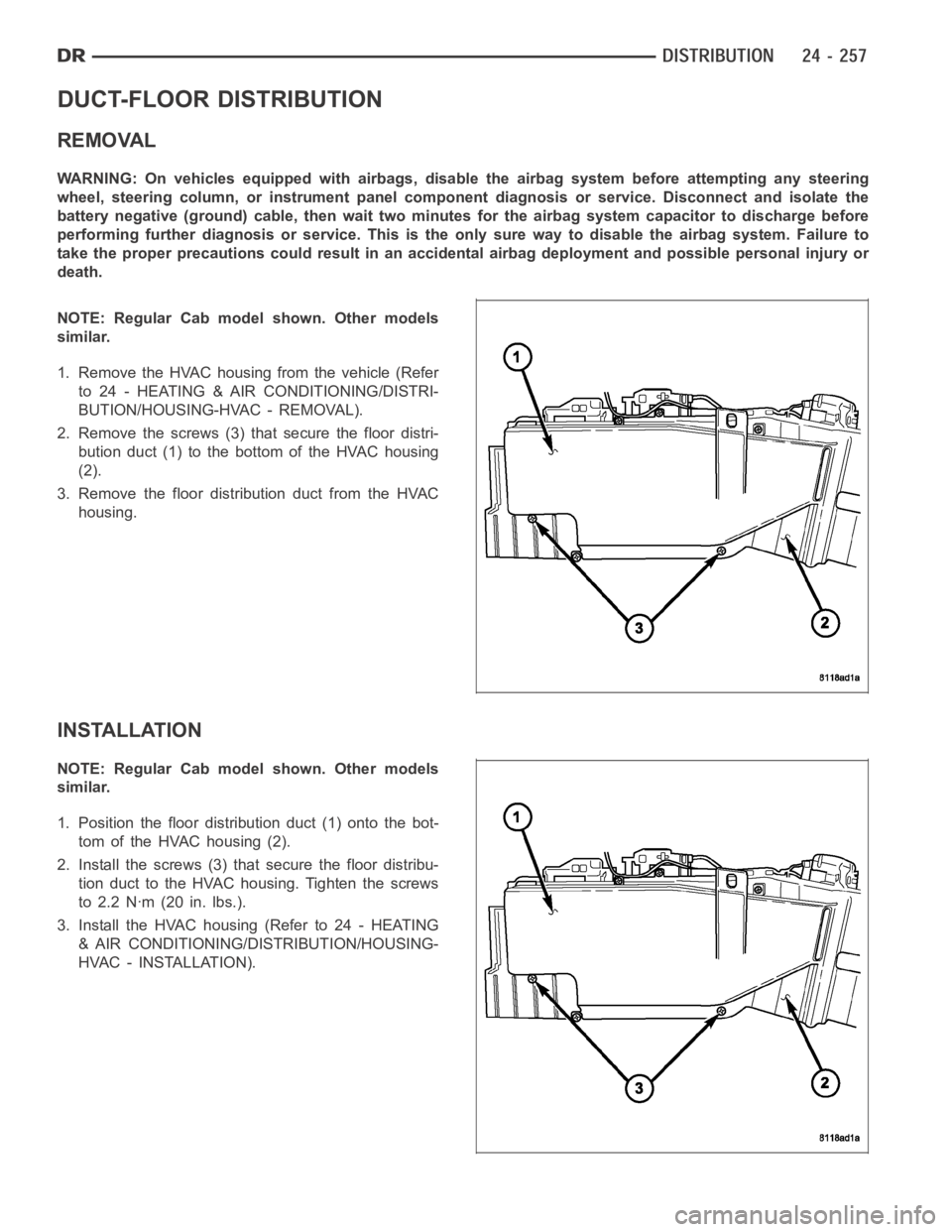
NOTE: Regular Cab model shown. Other models
similar.
1. Remove the HVAC housing from the vehicle (Refer
to 24 - HEATING & AIR CONDITIONING/DISTRI-
BUTION/HOUSING-HVAC - REMOVAL).
2. Remove the screws (3) that secure the floor distri-
bution duct (1) to the bottom of the HVAC housing
(2).
3. Remove the floor distribution duct from the HVAC
housing.
INSTALLATION
NOTE: Regular Cab model shown. Other models
similar.
1. Position the floor distribution duct (1) onto the bot-
tom of the HVAC housing (2).
2. Install the screws (3) that secure the floor distribu-
tion duct to the HVAC housing. Tighten the screws
to 2.2 Nꞏm (20 in. lbs.).
3. Install the HVAC housing (Refer to 24 - HEATING
& AIR CONDITIONING/DISTRIBUTION/HOUSING-
HVAC - INSTALLATION).
Page 5099 of 5267
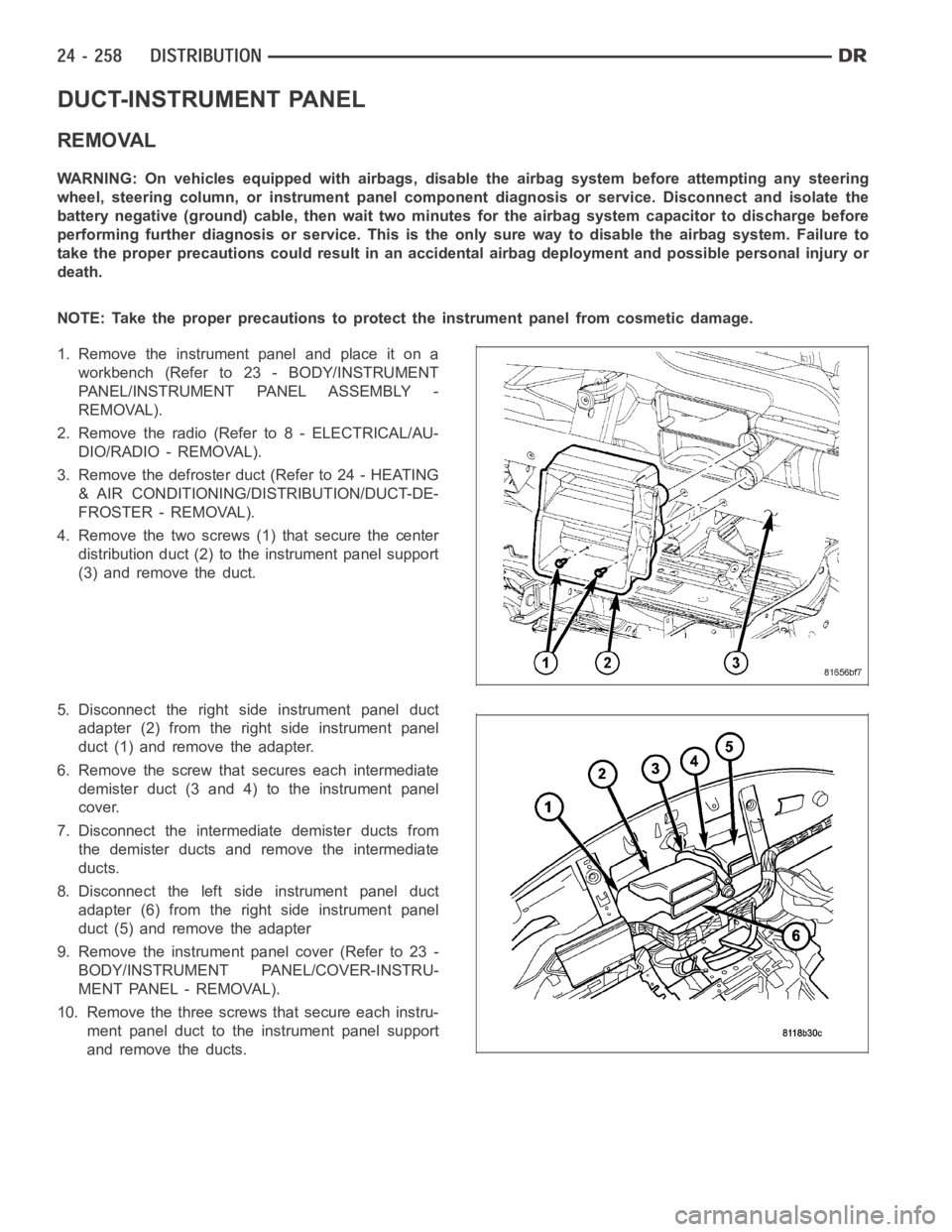
DUCT-INSTRUMENT PANEL
REMOVAL
WARNING: On vehicles equipped with airbags, disable the airbag system before attempting any steering
wheel, steering column, or instrument panel component diagnosis or service. Disconnect and isolate the
battery negative (ground) cable, then wait two minutes for the airbag system capacitor to discharge before
performing further diagnosis or service. This is the only sure way to disable the airbag system. Failure to
take the proper precautions could result in an accidental airbag deployment and possible personal injury or
death.
NOTE: Take the proper precautions to protect the instrument panel from cosmetic damage.
1. Remove the instrument panel and place it on a
workbench (Refer to 23 - BODY/INSTRUMENT
PANEL/INSTRUMENT PANEL ASSEMBLY -
REMOVAL).
2. Remove the radio (Refer to 8 - ELECTRICAL/AU-
DIO/RADIO - REMOVAL).
3. Remove the defroster duct (Refer to 24 - HEATING
& AIR CONDITIONING/DISTRIBUTION/DUCT-DE-
FROSTER - REMOVAL).
4. Remove the two screws (1) that secure the center
distribution duct (2) to the instrument panel support
(3) and remove the duct.
5. Disconnect the right side instrument panel duct
adapter (2) from the right side instrument panel
duct (1) and remove the adapter.
6. Remove the screw that secures each intermediate
demister duct (3 and 4) to the instrument panel
cover.
7. Disconnect the intermediate demister ducts from
the demister ducts and remove the intermediate
ducts.
8. Disconnect the left side instrument panel duct
adapter (6) from the right side instrument panel
duct (5) and remove the adapter
9. Remove the instrument panel cover (Refer to 23 -
BODY/INSTRUMENT PANEL/COVER-INSTRU-
MENT PANEL - REMOVAL).
10. Remove the three screws that secure each instru-
ment panel duct to the instrument panel support
and remove the ducts.
Page 5101 of 5267
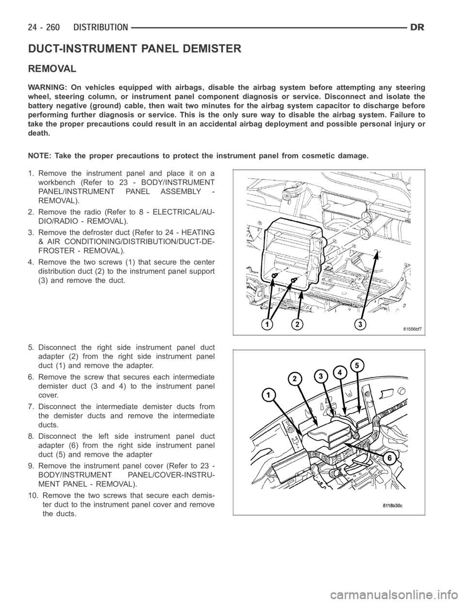
DUCT-INSTRUMENT PANEL DEMISTER
REMOVAL
WARNING: On vehicles equipped with airbags, disable the airbag system before attempting any steering
wheel, steering column, or instrument panel component diagnosis or service. Disconnect and isolate the
battery negative (ground) cable, then wait two minutes for the airbag system capacitor to discharge before
performing further diagnosis or service. This is the only sure way to disable the airbag system. Failure to
take the proper precautions could result in an accidental airbag deployment and possible personal injury or
death.
NOTE: Take the proper precautions to protect the instrument panel from cosmetic damage.
1. Remove the instrument panel and place it on a
workbench (Refer to 23 - BODY/INSTRUMENT
PANEL/INSTRUMENT PANEL ASSEMBLY -
REMOVAL).
2. Remove the radio (Refer to 8 - ELECTRICAL/AU-
DIO/RADIO - REMOVAL).
3. Remove the defroster duct (Refer to 24 - HEATING
& AIR CONDITIONING/DISTRIBUTION/DUCT-DE-
FROSTER - REMOVAL).
4. Remove the two screws (1) that secure the center
distribution duct (2) to the instrument panel support
(3) and remove the duct.
5. Disconnect the right side instrument panel duct
adapter (2) from the right side instrument panel
duct (1) and remove the adapter.
6. Remove the screw that secures each intermediate
demister duct (3 and 4) to the instrument panel
cover.
7. Disconnect the intermediate demister ducts from
the demister ducts and remove the intermediate
ducts.
8. Disconnect the left side instrument panel duct
adapter (6) from the right side instrument panel
duct (5) and remove the adapter
9. Remove the instrument panel cover (Refer to 23 -
BODY/INSTRUMENT PANEL/COVER-INSTRU-
MENT PANEL - REMOVAL).
10. Remove the two screwsthat secure each demis-
ter duct to the instrument panel cover and remove
the ducts.
Page 5103 of 5267
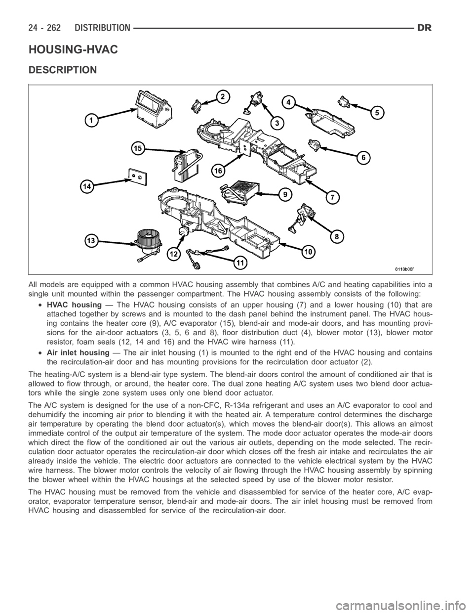
HOUSING-HVAC
DESCRIPTION
All models are equipped with a common HVAC housing assembly that combines A/C and heating capabilities into a
single unit mounted within the passenger compartment. The HVAC housing assembly consists of the following:
HVAC housing— The HVAC housing consists of an upper housing (7) and a lower housing (10) that are
attached together by screws and is mounted to the dash panel behind the instrument panel. The HVAC hous-
ing contains the heater core (9), A/C evaporator (15), blend-air and mode-air doors, and has mounting provi-
sions for the air-door actuators (3, 5, 6 and 8), floor distribution duct (4), blower motor (13), blower motor
resistor, foam seals (12, 14 and 16) and the HVAC wire harness (11).
Air inlet housing— The air inlet housing (1) is mounted to the right end of the HVAC housing andcontains
the recirculation-air door and has mounting provisions for the recirculation door actuator (2).
The heating-A/C system is a blend-air type system. The blend-air doors control the amount of conditioned air that is
allowed to flow through, or around, the heater core. The dual zone heating A/C system uses two blend door actua-
tors while the single zone system uses only one blend door actuator.
The A/C system is designed for the use of a non-CFC, R-134a refrigerant and uses an A/C evaporator to cool and
dehumidify the incoming air prior to blending it with the heated air. A temperature control determines the discharge
air temperature by operating the blend door actuator(s), which moves the blend-air door(s). This allows an almost
immediate control of the output air temperature of the system. The mode door actuator operates the mode-air doors
which direct the flow of the conditioned air out the various air outlets, depending on the mode selected. The recir-
culation door actuator operates the recirculation-air door which closesoff the fresh air intake and recirculates the air
already inside the vehicle. The electric door actuators are connected to the vehicle electrical system by the HVAC
wire harness. The blower motor controls the velocity of air flowing through the HVAC housing assembly by spinning
the blower wheel within the HVAC housings at the selected speed by use of theblower motor resistor.
The HVAC housing must be removed from the vehicle and disassembled for service of the heater core, A/C evap-
orator, evaporator temperature sensor, blend-air and mode-air doors. The air inlet housing must be removed from
HVAC housing and disassembled for service of the recirculation-air door.
Page 5104 of 5267
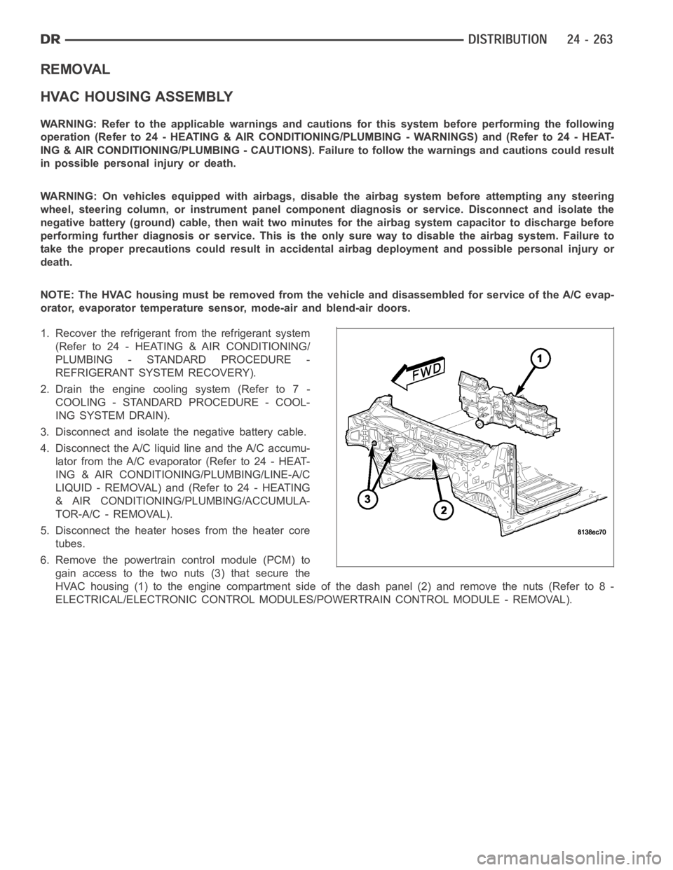
REMOVAL
HVAC HOUSING ASSEMBLY
WARNING: Refer to the applicable warnings and cautions for this system before performing the following
operation (Refer to 24 - HEATING & AIR CONDITIONING/PLUMBING - WARNINGS) and (Refer to 24 - HEAT-
ING & AIR CONDITIONING/PLUMBING - CAUTIONS). Failure to follow the warnings and cautions could result
in possible personal injury or death.
WARNING: On vehicles equipped with airbags, disable the airbag system before attempting any steering
wheel, steering column, or instrument panel component diagnosis or service. Disconnect and isolate the
negative battery (ground) cable, then wait two minutes for the airbag system capacitor to discharge before
performing further diagnosis or service. This is the only sure way to disable the airbag system. Failure to
take the proper precautions could result in accidental airbag deploymentand possible personal injury or
death.
NOTE: The HVAC housing must be removedfrom the vehicle and disassembled for service of the A/C evap-
orator, evaporator temperature sensor, mode-air and blend-air doors.
1. Recover the refrigerant from the refrigerant system
(Refer to 24 - HEATING & AIR CONDITIONING/
PLUMBING - STANDARD PROCEDURE -
REFRIGERANT SYSTEM RECOVERY).
2. Drain the engine cooling system (Refer to 7 -
COOLING - STANDARD PROCEDURE - COOL-
ING SYSTEM DRAIN).
3. Disconnect and isolate the negative battery cable.
4. Disconnect the A/C liquid line and the A/C accumu-
lator from the A/C evaporator (Refer to 24 - HEAT-
ING & AIR CONDITIONING/PLUMBING/LINE-A/C
LIQUID - REMOVAL) and (Refer to 24 - HEATING
& AIR CONDITIONING/PLUMBING/ACCUMULA-
TOR-A/C - REMOVAL).
5. Disconnect the heater hoses from the heater core
tubes.
6. Remove the powertrain control module (PCM) to
gain access to the two nuts (3) that secure the
HVAC housing (1) to the engine compartment side of the dash panel (2) and remove the nuts (Refer to 8 -
ELECTRICAL/ELECTRONIC CONTROL MODULES/POWERTRAIN CONTROL MODULE - REMOVAL).