2006 DODGE RAM SRT-10 service
[x] Cancel search: servicePage 4177 of 5267
page page
TRANSFER CASE - NV243 - SERVICE
INFORMATION
DESCRIPTION ............................. 1657
OPERATION ............................... 1657
DIAGNOSIS AND TESTING - TRANSFER
CASE - NV243 ............................ 1658
REMOVAL ................................. 1659
DISASSEMBLY ............................. 1659
CLEANING ................................. 1671
INSPECTION ............................... 1671
ASSEMBLY . ............................... 1674
INSTALLATION ............................. 1686
SPECIFICATIONS
TRANSFER CASE - NV243 ................ 1686
SPECIAL TOOLS
TRANSFER CASE - NV243 ................ 1687
SEAL-EXTENSION HOUSING
REMOVAL ................................. 1689
INSTALLATION ............................. 1689
FLUID
STANDARD PROCEDURE - FLUID DRAIN AND
REFILL ................................... 1690SEAL-FRONT OUTPUT SHAFT
REMOVAL ................................. 1691
INSTALLATION ............................. 1692
SENSOR-MODE
DESCRIPTION ............................. 1693
OPERATION ............................... 1693
SWITCH-SELECTOR
DESCRIPTION ............................. 1695
OPERATION ............................... 1695
MOTOR-SHIFT
DESCRIPTION ............................. 1697
OPERATION ............................... 1697
REMOVAL ................................. 1697
INSTALLATION ............................. 1697
ASSEMBLY-SHIFT MOTOR/MODE SENSOR
DESCRIPTION ............................. 1699
OPERATION ............................... 1699
Page 4178 of 5267
TRANSFER CASE - NV243 - SERVICE INFORMATION
DESCRIPTION
The NV243 is an electronically controlled part-time transfer case with a low range gear reduction system. The
NV243 has three operating ranges plus a NEUTRAL position. The low range system provides a gear reduction ratio
for increased low speed torque capability.
The geartrain is mounted in two aluminum case halves attached with bolts. The mainshaft front and rear bearings
are mounted in aluminum retainer housings bolted to the case halves.
OPERATING RANGES
Transfer case operating ranges are:
2WD (2-wheel drive).
4HI (4-wheel drive).
4LO (4-wheel drive low range).
NEUTRAL.
The 2WD range is for use on any road surface at any time.
The 4HI and 4LO ranges are for off road use only. They are not for use on hard surface roads. The only exception
being when the road surface is wet or slippery or covered by ice and snow.
The low range reduction gear system is operative in 4LO range only. This range is for extra pulling power in off road
situations. Low range reduction ratio is 2.72:1.
SHIFT MECHANISM
Operating ranges are selected with a dash mounted shift selector switch. The shift selector switch provides a input
to the Transfer Case Control Module (TCCM) to indicate the driver’s desireto change operating ranges. The TCCM
uses this input, along with input from the transfer case mounted mode sensor and information from the vehicle’s
bus, to determine if a shift is permitted. If the TCCM decides the shift is permitted, the TCCM controls the shift
motor, mounted to the exterior of the transfer case, to perform the shift.
IDENTIFICATION
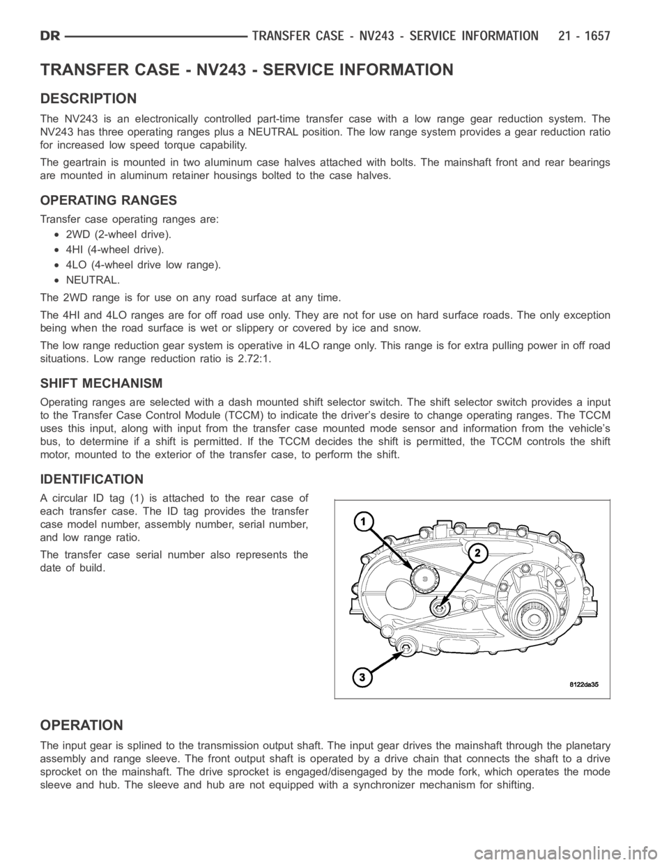
A circular ID tag (1) is attached to the rear case of
each transfer case. The ID tag provides the transfer
case model number, assembly number, serial number,
and low range ratio.
The transfer case serial number also represents the
date of build.
OPERATION
The input gear is splined to the transmission output shaft. The input gear drives the mainshaft through the planetary
assembly and range sleeve. The front output shaft is operated by a drive chain that connects the shaft to a drive
sprocket on the mainshaft. The drive sprocket is engaged/disengaged by themodefork,whichoperatesthemode
sleeve and hub. The sleeve and hub are not equipped with a synchronizer mechanism for shifting.
Page 4194 of 5267
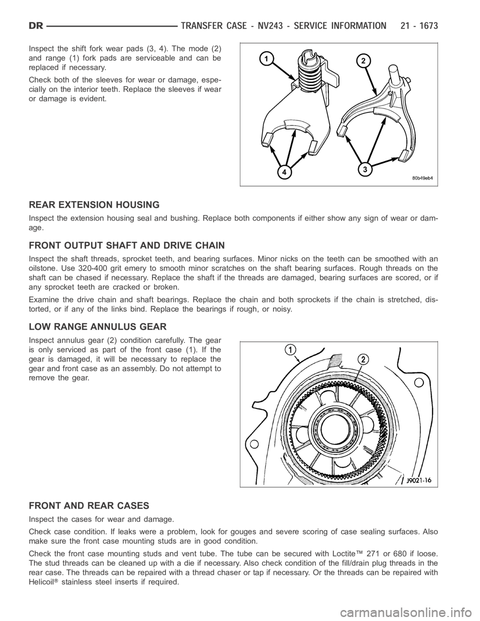
Inspect the shift fork wear pads (3, 4). The mode (2)
and range (1) fork pads are serviceable and can be
replaced if necessary.
Check both of the sleeves for wear or damage, espe-
cially on the interior teeth. Replace the sleeves if wear
or damage is evident.
REAR EXTENSION HOUSING
Inspect the extension housing seal and bushing. Replace both components if either show any sign of wear or dam-
age.
FRONT OUTPUT SHAFT AND DRIVE CHAIN
Inspect the shaft threads, sprocket teeth, and bearing surfaces. Minor nicksontheteethcanbesmoothedwithan
oilstone. Use 320-400 grit emery to smooth minor scratches on the shaft bearing surfaces. Rough threads on the
shaft can be chased if necessary. Replace the shaft if the threads are damaged, bearing surfaces are scored, or if
any sprocket teeth are cracked or broken.
Examine the drive chain and shaft bearings. Replace the chain and both sprockets if the chain is stretched, dis-
torted, or if any of the links bind. Replace the bearings if rough, or noisy.
LOW RANGE ANNULUS GEAR
Inspect annulus gear (2) condition carefully. The gear
is only serviced as part of the front case (1). If the
gear is damaged, it will be necessary to replace the
gear and front case as an assembly. Do not attempt to
remove the gear.
FRONT AND REAR CASES
Inspect the cases for wear and damage.
Check case condition. If leaks were a problem, look for gouges and severe scoring of case sealing surfaces. Also
make sure the front case mounting studs are in good condition.
Check the front case mounting studs and vent tube. The tube can be secured with Loctite™ 271 or 680 if loose.
Thestudthreadscanbecleanedupwithadieifnecessary.Alsocheckcondition of the fill/drain plug threads in the
rear case. The threads can be repaired with a thread chaser or tap if necessary. Or the threads can be repaired with
Helicoil
stainless steel inserts if required.
Page 4195 of 5267
OIL PUMP/OIL PICKUP
Examine the oil pump pickup parts. Replace the pump if any part appears to beworn or damaged. Do not disas-
semble the pump as individual parts are not available. The pump is only available as a complete assembly. The
pickup screen, hose, and tube are the only serviceable parts and are available separately.
ASSEMBLY
BEARINGS AND SEALS
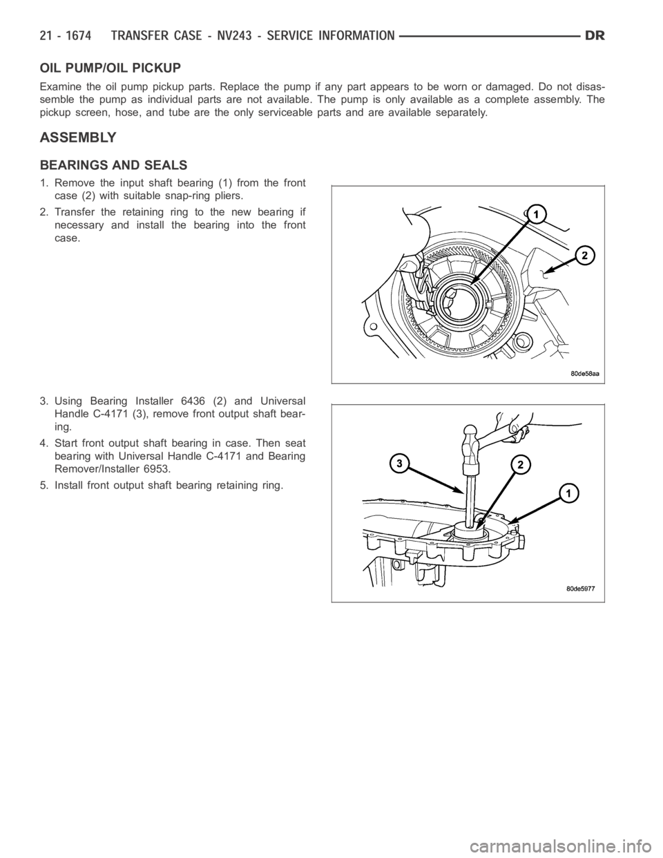
1. Remove the input shaft bearing (1) from the front
case (2) with suitable snap-ring pliers.
2. Transfer the retaining ring to the new bearing if
necessary and install the bearing into the front
case.
3. Using Bearing Installer 6436 (2) and Universal
Handle C-4171 (3), remove front output shaft bear-
ing.
4. Start front output shaft bearing in case. Then seat
bearing with Universal Handle C-4171 and Bearing
Remover/Installer 6953.
5. Install front output shaft bearing retaining ring.
Page 4221 of 5267
page page
TRANSFER CASE - NV244 GENII - SERVICE
INFORMATION
DESCRIPTION ............................. 1701
OPERATION ............................... 1701
DIAGNOSIS AND TESTING
TRANSFER CASE - NV244 ................ 1702
REMOVAL ................................. 1703
DISASSEMBLY ............................. 1703
CLEANING ................................. 1715
INSPECTION ............................... 1715
ASSEMBLY . ............................... 1718
INSTALLATION ............................. 1730
SPECIFICATIONS
TRANSFER CASE - NV244 GENII .......... 1730
SPECIAL TOOLS
TRANSFER CASE - NV244 GENII .......... 1731
SEAL-EXTENSION HOUSING
REMOVAL ................................. 1733INSTALLATION ............................. 1733
FLUID
STANDARD PROCEDURE - FLUID DRAIN AND
REFILL ................................... 1734
SEAL-FRONT OUTPUT SHAFT
REMOVAL ................................. 1735
INSTALLATION ............................. 1736
SENSOR-MODE
DESCRIPTION ............................. 1737
OPERATION ............................... 1737
SWITCH-TRANSFER CASE SELECTOR
DESCRIPTION ............................. 1739
OPERATION ............................... 1739
MOTOR-SHIFT
DESCRIPTION ............................. 1741
OPERATION ............................... 1741
REMOVAL ................................. 1741
INSTALLATION ............................. 1741
Page 4222 of 5267
TRANSFER CASE - NV244 GENII - SERVICE INFORMATION
DESCRIPTION
The NV244 GENII is an electronically controlled full and part-time transfer case with no two wheel drive operation.
A differential in the transfer case is used to control torque transfer to the front and rear axles. A low range gear
reduction system provides increased low speed torque capability for off road operation. The low range provides a
2.72:1 reduction ratio.
The geartrain is mounted in two aluminum case halves attached with bolts. The mainshaft front and rear bearings
are mounted in aluminum retainer housings bolted to the case halves.
OPERATING RANGES
NV244 GENII operating ranges are:
AWD (All-Wheel Drive).
4LOCK (Part-time).
4LO.
NEUTRAL.
The AWD mode can be used at any time and on any road surface.
The 4LOCK (Part-time) and 4LO ranges are for off road use only. The only timetheserangescanbeusediswhen
the road surface is covered with snow, ice, or other loose slippery material.
SHIFT MECHANISM
Operating ranges are selected with a dash mounted shift selector switch. The shift selector switch provides a input
to the Front Control Module (FCM) to indicate the driver’s desire to changeoperating ranges. The FCM uses this
input, along with the input from the transfer case mounted mode sensor and information from the vehicle’s bus, to
determine if a shift is permitted. If the FCM decides the shift is permitted, the FCM controls the shift motor, mounted
to the exterior of the transfer case, to perform the shift.
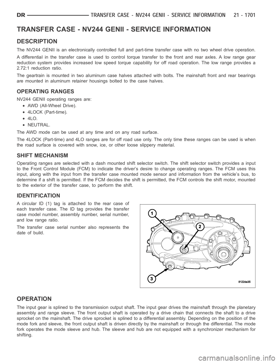
IDENTIFICATION
A circular ID (1) tag is attached to the rear case of
each transfer case. The ID tag provides the transfer
case model number, assembly number, serial number,
and low range ratio.
The transfer case serial number also represents the
date of build.
OPERATION
The input gear is splined to the transmission output shaft. The input gear drives the mainshaft through the planetary
assembly and range sleeve. The front output shaft is operated by a drive chain that connects the shaft to a drive
sprocket on the mainshaft. The drive sprocket is splined to a differentialassembly. Depending on the position of the
mode fork and sleeve, the front output shaft is driven directly by the mainshaft or through the differential. The mode
fork operates the mode sleeve and hub. The sleeve and hub are not equipped with a synchronizer mechanism for
shifting.
Page 4237 of 5267
INPUT GEAR AND PLANETARY CARRIER
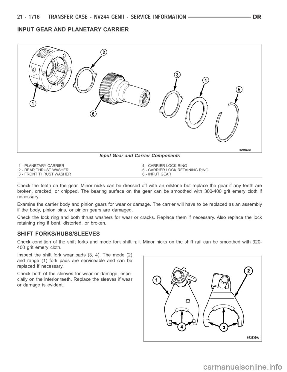
Check the teeth on the gear. Minor nicks can be dressed off with an oilstone but replace the gear if any teeth are
broken, cracked, or chipped. The bearing surface on the gear can be smoothed with 300-400 grit emery cloth if
necessary.
Examine the carrier body and pinion gears for wear or damage. The carrier will have to be replaced as an assembly
if the body, pinion pins, or pinion gears are damaged.
Check the lock ring and both thrust washers for wear or cracks. Replace themif necessary. Also replace the lock
retaining ring if bent, distorted, or broken.
SHIFT FORKS/HUBS/SLEEVES
Check condition of the shift forks and mode fork shift rail. Minor nicks on the shift rail can be smoothed with 320-
400 grit emery cloth.
Inspect the shift fork wear pads (3, 4). The mode (2)
and range (1) fork pads are serviceable and can be
replaced if necessary.
Check both of the sleeves for wear or damage, espe-
cially on the interior teeth. Replace the sleeves if wear
or damage is evident.
Input Gear and Carrier Components
1 - PLANETARY CARRIER 4 - CARRIER LOCK RING
2 - REAR THRUST WASHER 5 - CARRIER LOCK RETAINING RING
3 - FRONT THRUST WASHER 6 - INPUT GEAR
Page 4238 of 5267
REAR EXTENSION HOUSING
Inspect the extension housing seal and bushing. Replace both components if either show any sign of wear or dam-
age.
FRONT OUTPUT SHAFT AND DRIVE CHAIN
Inspect the shaft splines and bearing surfaces. Minor nicks on the splinescanbesmoothedwithanoilstone.Use
320-400 grit emery to smooth minor scratches on the shaft bearing surfaces. Replace the shaft if the bearing sur-
faces are scored or if any of the splines are cracked or broken.
Examine the drive chain and shaft bearings. Replace the chain and both sprockets if the chain is stretched, dis-
torted, or if any of the links bind. Replace the bearings if rough, or noisy.
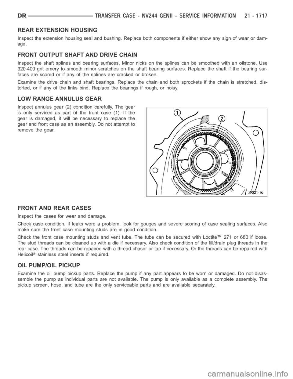
LOW RANGE ANNULUS GEAR
Inspect annulus gear (2) condition carefully. The gear
is only serviced as part of the front case (1). If the
gear is damaged, it will be necessary to replace the
gear and front case as an assembly. Do not attempt to
remove the gear.
FRONT AND REAR CASES
Inspect the cases for wear and damage.
Check case condition. If leaks were a problem, look for gouges and severe scoring of case sealing surfaces. Also
make sure the front case mounting studs are in good condition.
Check the front case mounting studs and vent tube. The tube can be secured with Loctite™ 271 or 680 if loose.
Thestudthreadscanbecleanedupwithadieifnecessary.Alsocheckcondition of the fill/drain plug threads in the
rear case. The threads can be repaired with a thread chaser or tap if necessary. Or the threads can be repaired with
Helicoil
stainless steel inserts if required.
OIL PUMP/OIL PICKUP
Examine the oil pump pickup parts. Replace the pump if any part appears to beworn or damaged. Do not disas-
semble the pump as individual parts are not available. The pump is only available as a complete assembly. The
pickup screen, hose, and tube are the only serviceable parts and are available separately.