Page 4608 of 5267
SUNROOF - SERVICE INFORMATION
DESCRIPTION
Parts List
EXPLODED VIEW
Page 4626 of 5267
GUIDE-SUNROOF GLASS
REMOVAL
1. Place the sunroof in the vent position.
2. Remove the sunroof assembly. (Refer to 23 -
BODY/SUNROOF/ASSEMBLY-MODULE -
REMOVAL)
3. Remove the motor. (Refer to 8 - ELECTRICAL/
POWER TOP - SUNROOF SERVICE INFO/MO-
TOR/MODULE-SUNROOF - REMOVAL)
4. Remove the glass. (Refer to 23 - BODY/SUN-
ROOF/GLASS - REMOVAL)
5. Remove the wind deflector. (Refer to 23 - BODY/
SUNROOF/DEFLECTOR-WIND - REMOVAL)
6. Separate the drain channel arms (2) from the guide
mechanisms (1) one at a time.
CAUTION: Do not pry the channel arms apart at
the same time or you could break the drain chan-
nel.
7. Slide the drain channel rearward out of the way.
8. Remove the hard stop screw from the frame.
Page 4629 of 5267

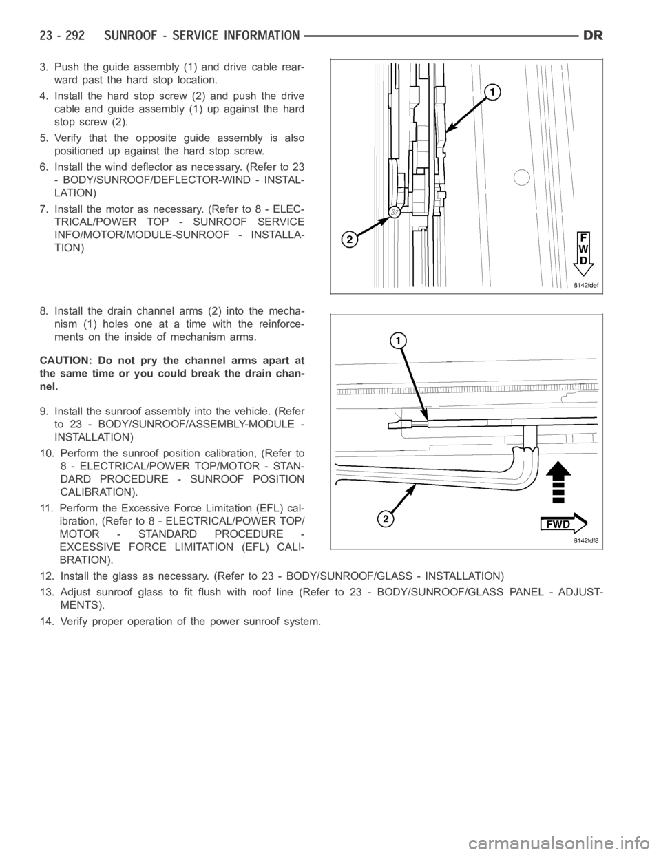
3. Push the guide assembly (1) and drive cable rear-
ward past the hard stop location.
4. Install the hard stop screw (2) and push the drive
cable and guide assembly (1) up against the hard
stop screw (2).
5. Verify that the opposite guide assembly is also
positioned up against the hard stop screw.
6. Install the wind deflector as necessary. (Refer to 23
- BODY/SUNROOF/DEFLECTOR-WIND - INSTAL-
LATION)
7. Install the motor as necessary. (Refer to 8 - ELEC-
TRICAL/POWER TOP - SUNROOF SERVICE
INFO/MOTOR/MODULE-SUNROOF - INSTALLA-
TION)
8. Install the drain channel arms (2) into the mecha-
nism (1) holes one at a time with the reinforce-
ments on the inside of mechanism arms.
CAUTION: Do not pry the channel arms apart at
the same time or you could break the drain chan-
nel.
9. Install the sunroof assembly into the vehicle. (Refer
to 23 - BODY/SUNROOF/ASSEMBLY-MODULE -
INSTALLATION)
10. Perform the sunroof position calibration, (Refer to
8 - ELECTRICAL/POWER TOP/MOTOR - STAN-
DARD PROCEDURE - SUNROOF POSITION
CALIBRATION).
11. Perform the Excessive Force Limitation (EFL) cal-
ibration, (Refer to 8 - ELECTRICAL/POWER TOP/
MOTOR - STANDARD PROCEDURE -
EXCESSIVE FORCE LIMITATION (EFL) CALI-
BRATION).
12. Install the glass as necessary. (Refer to 23 - BODY/SUNROOF/GLASS - INSTA L L AT I O N )
13. Adjust sunroof glass to fit flush with roof line (Refer to 23 - BODY/SUNROOF/GLASS PANEL - ADJUST-
MENTS).
14. Verify proper operation of the power sunroof system.
Page 4632 of 5267
MOTOR
DESCRIPTION
For service information refer to (Refer to 8 - ELECTRICAL/POWER TOP/MOTOR- DIAGNOSIS AND TESTING).
Page 4635 of 5267
SWITCH-SUNROOF
DESCRIPTION
For service information refer to (Refer to 8 - ELECTRICAL/POWER TOP/SWITCH - DIAGNOSIS AND TESTING).
Page 4848 of 5267

4.CHECK (C33) PASSENGER BLEND DOOR DRIVER CIRCUIT FOR A SHORT TO (C34) COMMONDOOR
DRIVER CIRCUIT
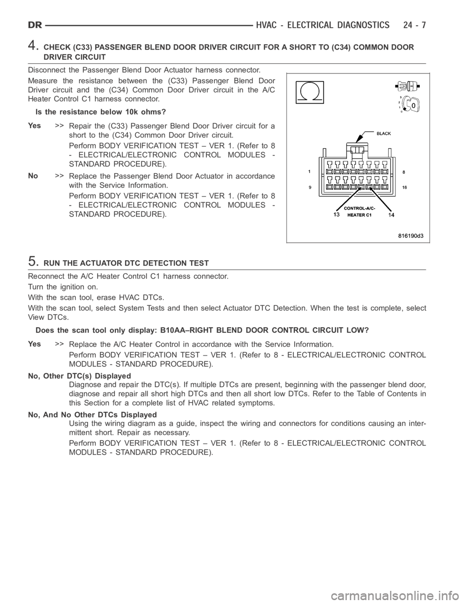
Disconnect the Passenger Blend Door Actuator harness connector.
Measure the resistance between the (C33) Passenger Blend Door
Driver circuit and the (C34) Common Door Driver circuit in the A/C
Heater Control C1 harness connector.
Istheresistancebelow10kohms?
Ye s>>
Repair the (C33) Passenger Blend Door Driver circuit for a
short to the (C34) Common Door Driver circuit.
Perform BODY VERIFICATION TEST – VER 1. (Refer to 8
- ELECTRICAL/ELECTRONIC CONTROL MODULES -
STANDARD PROCEDURE).
No>>
Replace the Passenger Blend Door Actuator in accordance
with the Service Information.
Perform BODY VERIFICATION TEST – VER 1. (Refer to 8
- ELECTRICAL/ELECTRONIC CONTROL MODULES -
STANDARD PROCEDURE).
5.RUN THE ACTUATOR DTC DETECTION TEST
Reconnect the A/C Heater Control C1 harness connector.
Turn the ignition on.
With the scan tool, erase HVAC DTCs.
With the scan tool, select System Tests and then select Actuator DTC Detection. When the test is complete, select
View DTCs.
Does the scan tool only display: B10AA–RIGHT BLEND DOOR CONTROL CIRCUIT LOW?
Ye s>>
Replace the A/C Heater Control in accordance with the Service Information.
Perform BODY VERIFICATION TEST – VER 1. (Refer to 8 - ELECTRICAL/ELECTRONIC CONTROL
MODULES - STANDARD PROCEDURE).
No, Other DTC(s) Displayed
Diagnose and repair the DTC(s). If multiple DTCs are present, beginning with the passenger blend door,
diagnose and repair all short high DTCs and then all short low DTCs. Refer tothe Table of Contents in
this Section for a complete list of HVAC related symptoms.
No, And No Other DTCs Displayed
Using the wiring diagram as a guide, inspect the wiring and connectors for conditions causing an inter-
mittent short. Repair as necessary.
Perform BODY VERIFICATION TEST – VER 1. (Refer to 8 - ELECTRICAL/ELECTRONIC CONTROL
MODULES - STANDARD PROCEDURE).
Page 4850 of 5267

Theory of Operation
The A/C Heater Control drives the Passenger Blend Door Actuator via the (C33) Passenger Blend Door Driver cir-
cuit and the (C34) Common Door Driver circuit. All of the door actuators share the (C34) Common Door Driver
circuit. Inside the A/C Heater Control, each door actuator has its own unique driver, but all share a single common
door driver circuit. Due to the shared circuitry similar DTCs can set at thesame time for multiple actuators depend-
ing upon the type of short, its location, and the direction the actuator is moving when the short is present.
When Monitored:
When the Actuator DTC Detection Test is executed.
Set Condition:
If the (C33) Passenger Blend Door Driver circuit is shorted to voltage.
Possible Causes
(C33) PASSENGER BLEND DOOR DRIVERCIRCUIT SHORTED TO VOLTAGE
A/C HEATER CONTROL
Diagnostic Test
1.CHECK (C33) PASSENGER BLEND DOOR DRIVER CIRCUIT FOR A SHORT TO VOLTAGE
Turn the ignition off.
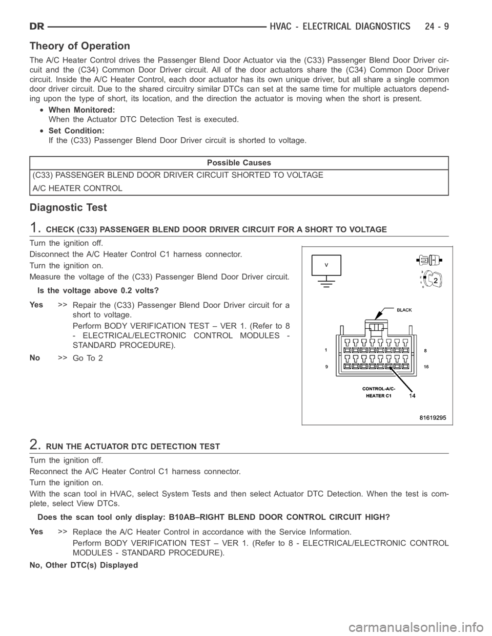
Disconnect the A/C Heater Control C1 harness connector.
Turn the ignition on.
Measure the voltage of the (C33) Passenger Blend Door Driver circuit.
Is the voltage above 0.2 volts?
Ye s>>
Repair the (C33) Passenger Blend Door Driver circuit for a
short to voltage.
Perform BODY VERIFICATION TEST – VER 1. (Refer to 8
- ELECTRICAL/ELECTRONIC CONTROL MODULES -
STANDARD PROCEDURE).
No>>
Go To 2
2.RUN THE ACTUATOR DTC DETECTION TEST
Turn the ignition off.
Reconnect the A/C Heater Control C1 harness connector.
Turn the ignition on.
With the scan tool in HVAC, select System Tests and then select Actuator DTCDetection. When the test is com-
plete, select View DTCs.
Does the scan tool only display: B10AB–RIGHT BLEND DOOR CONTROL CIRCUIT HIGH?
Ye s>>
Replace the A/C Heater Control in accordance with the Service Information.
Perform BODY VERIFICATION TEST – VER 1. (Refer to 8 - ELECTRICAL/ELECTRONIC CONTROL
MODULES - STANDARD PROCEDURE).
No, Other DTC(s) Displayed
Page 4854 of 5267

3.CHECK (C33) PASSENGER BLEND DOOR DRIVER CIRCUIT FOR AN OPEN
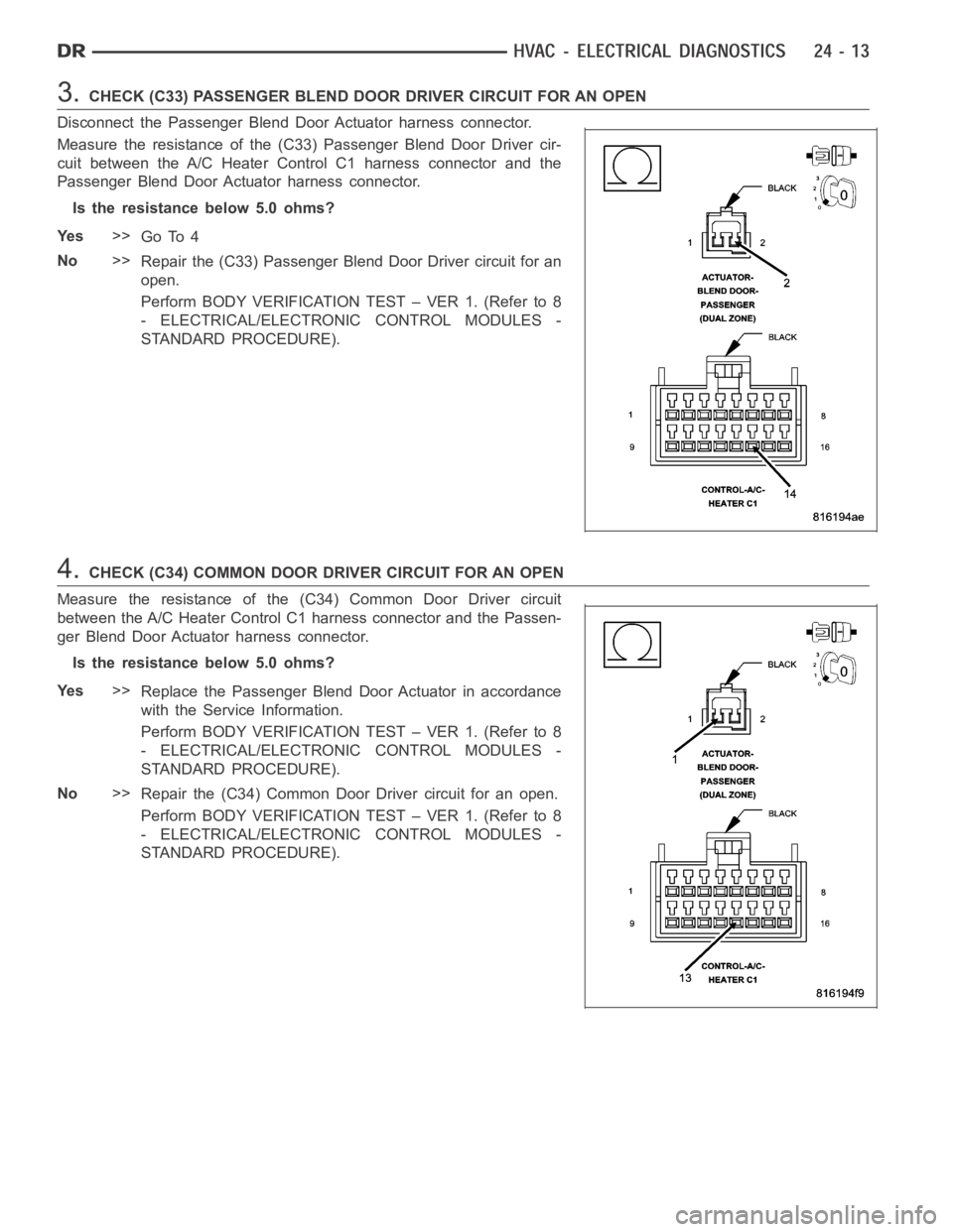
Disconnect the Passenger Blend Door Actuator harness connector.
Measure the resistance of the (C33) Passenger Blend Door Driver cir-
cuit between the A/C Heater Control C1 harness connector and the
Passenger Blend Door Actuator harness connector.
Is the resistance below 5.0 ohms?
Ye s>>
Go To 4
No>>
Repair the (C33) Passenger Blend Door Driver circuit for an
open.
Perform BODY VERIFICATION TEST – VER 1. (Refer to 8
- ELECTRICAL/ELECTRONIC CONTROL MODULES -
STANDARD PROCEDURE).
4.CHECK (C34) COMMON DOOR DRIVER CIRCUIT FOR AN OPEN
Measure the resistance of the (C34) Common Door Driver circuit
between the A/C Heater Control C1 harness connector and the Passen-
ger Blend Door Actuator harness connector.
Is the resistance below 5.0 ohms?
Ye s>>
Replace the Passenger Blend Door Actuator in accordance
with the Service Information.
Perform BODY VERIFICATION TEST – VER 1. (Refer to 8
- ELECTRICAL/ELECTRONIC CONTROL MODULES -
STANDARD PROCEDURE).
No>>
Repair the (C34) Common Door Driver circuit for an open.
Perform BODY VERIFICATION TEST – VER 1. (Refer to 8
- ELECTRICAL/ELECTRONIC CONTROL MODULES -
STANDARD PROCEDURE).