Page 4926 of 5267
>>
Diagnose and repair the DTC(s). If multiple DTCs are present, beginning with the common circuit, diag-
nose and repair all short high DTCs first and then all short low DTCs. Refer to the Table of Contents in
this Section for a complete list of HVAC related symptoms.
No>>
Go To 4
4.INSPECT ACTUATOR & HOUSING ASSEMBLY FOR A CONDITION CAUSING THE DOOR TO SEIZE OR
BIND
Turn the ignition off.
Inspect the actuator and the housing assembly for a condition causing the door to seize or bind.
Are there any physical or mechanical problems with the door, housing, or actuator?
Ye s>>
Repair as necessary in accordance with the Service Information.
Perform BODY VERIFICATION TEST – VER 1. (Refer to 8 - ELECTRICAL/ELECTRONIC CONTROL
MODULES - STANDARD PROCEDURE).
No>>
Go To 5
5.CHECK RECIRCULATION DOOR TRAVEL
Remove the Recirculation Door Actuator from the A/C Heater Housing Assembly.
By hand, attempt to rotate the door in both directions. The door should operate smoothly in both directions over
approximately 95 degrees of travel.
Does the door operate smoothly in both directions over approximately 95 degrees of travel?
Ye s>>
Replace the Recirculation Door Actuator in accordance with the Service Information. Then, Go To 6
No>>
Repair as necessary in accordance with the Service Information.
Perform BODY VERIFICATION TEST – VER 1. (Refer to 8 - ELECTRICAL/ELECTRONIC CONTROL
MODULES - STANDARD PROCEDURE).
6.RUN ACTUATOR CALIBRATION TEST
Turn the ignition on.
With the scan tool, select System Tests and then select Actuator Calibration Test. When the test is complete, select
View DTCs.
Does the scan tool display: B105C–RECIRCULATION DOOR TRAVEL RANGE TOO SMALL?
Ye s>>
Replace the A/C Heater Control in accordance with the Service Information.
Perform BODY VERIFICATION TEST – VER 1. (Refer to 8 - ELECTRICAL/ELECTRONIC CONTROL
MODULES - STANDARD PROCEDURE).
No>>
Perform BODY VERIFICATION TEST – VER 1. (Refer to 8 - ELECTRICAL/ELECTRONIC CONTROL
MODULES - STANDARD PROCEDURE).
Page 4928 of 5267
3.RUN THE ACTUATOR DTC DETECTION TEST
With the scan tool in HVAC, select System Tests and then select Actuator DTCDetection. When the test is com-
plete, select View DTCs.
Does the scan tool display any DTCs?
Yes, Dual-Zone System
Diagnose and repair the DTC(s). If multiple DTCs are present, beginning with the passenger blend door,
diagnose and repair all short high DTCs and then all short low DTCs. Refer tothe Table of Contents in
this Section for a complete list of HVAC related symptoms.
Yes, Single-Zone System
Diagnose and repair the DTC(s). If multiple DTCs are present, beginning with the common circuit, diag-
nose and repair all short high DTCs first and then all short low DTCs. Refer to the Table of Contents in
this Section for a complete list of HVAC related symptoms.
No>>
Go To 4
4.CHECK FOR A BROKEN RECIRCULATION DOOR ACTUATOR
Turn the ignition off.
Remove the Recirculation Door Actuator from the A/C Heater Housing Assembly.
By hand, attempt to rotate the actuator in both directions.
Does the actuator turn in either direction?
Ye s>>
Replace the Recirculation Door Actuator in accordance with the Service Information.
Perform BODY VERIFICATION TEST – VER 1. (Refer to 8 - ELECTRICAL/ELECTRONIC CONTROL
MODULES - STANDARD PROCEDURE).
No>>
Go To 5
5.CHECK RECIRCULATION DOOR & A/C HEATER HOUSING FOR WARPED, WORN, DAMAGED, MISSING,
& BROKEN COMPONENTS
Inspect for a damaged or broken A/C Heater Housing Assembly, a warped, worn, or broken door, and missing door
seals. Rotate the door from stop to stop. The door should rotate approximately 95 degrees.
Are there any physical or mechanical problems with the door or housing?
Ye s>>
Repair as necessary in accordance with the Service Information.
Perform BODY VERIFICATION TEST – VER 1. (Refer to 8 - ELECTRICAL/ELECTRONIC CONTROL
MODULES - STANDARD PROCEDURE).
No>>
Replace the Recirculation Door Actuator in accordance with the Service Information. Then, Go To 6.
6.RUN ACTUATOR CALIBRATION TEST
Turn the ignition on.
With the scan tool, select System Tests and then select Actuator Calibration Test. When the test is complete, select
View DTCs.
Does the scan tool display: B105D–RECIRCULATION DOOR TRAVEL RANGE TOO LARGE?
Ye s>>
Replace the A/C Heater Control in accordance with the Service Information.
Perform BODY VERIFICATION TEST – VER 1. (Refer to 8 - ELECTRICAL/ELECTRONIC CONTROL
MODULES - STANDARD PROCEDURE).
No>>
Perform BODY VERIFICATION TEST – VER 1. (Refer to 8 - ELECTRICAL/ELECTRONIC CONTROL
MODULES - STANDARD PROCEDURE).
Page 4931 of 5267
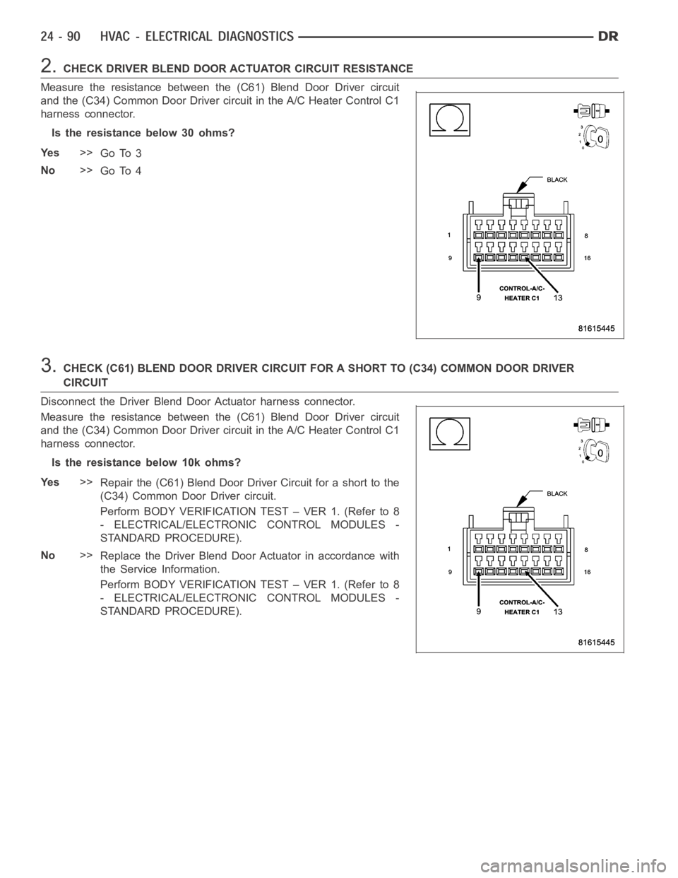
2.CHECK DRIVER BLEND DOOR ACTUATOR CIRCUIT RESISTANCE
Measure the resistance between the (C61) Blend Door Driver circuit
and the (C34) Common Door Driver circuit in the A/C Heater Control C1
harness connector.
Is the resistance below 30 ohms?
Ye s>>
Go To 3
No>>
Go To 4
3.CHECK (C61) BLEND DOOR DRIVER CIRCUIT FOR A SHORT TO (C34) COMMON DOOR DRIVER
CIRCUIT
Disconnect the Driver Blend Door Actuator harness connector.
Measure the resistance between the (C61) Blend Door Driver circuit
and the (C34) Common Door Driver circuit in the A/C Heater Control C1
harness connector.
Istheresistancebelow10kohms?
Ye s>>
Repair the (C61) Blend Door Driver Circuit for a short to the
(C34) Common Door Driver circuit.
Perform BODY VERIFICATION TEST – VER 1. (Refer to 8
- ELECTRICAL/ELECTRONIC CONTROL MODULES -
STANDARD PROCEDURE).
No>>
Replace the Driver Blend Door Actuator in accordance with
the Service Information.
Perform BODY VERIFICATION TEST – VER 1. (Refer to 8
- ELECTRICAL/ELECTRONIC CONTROL MODULES -
STANDARD PROCEDURE).
Page 4932 of 5267
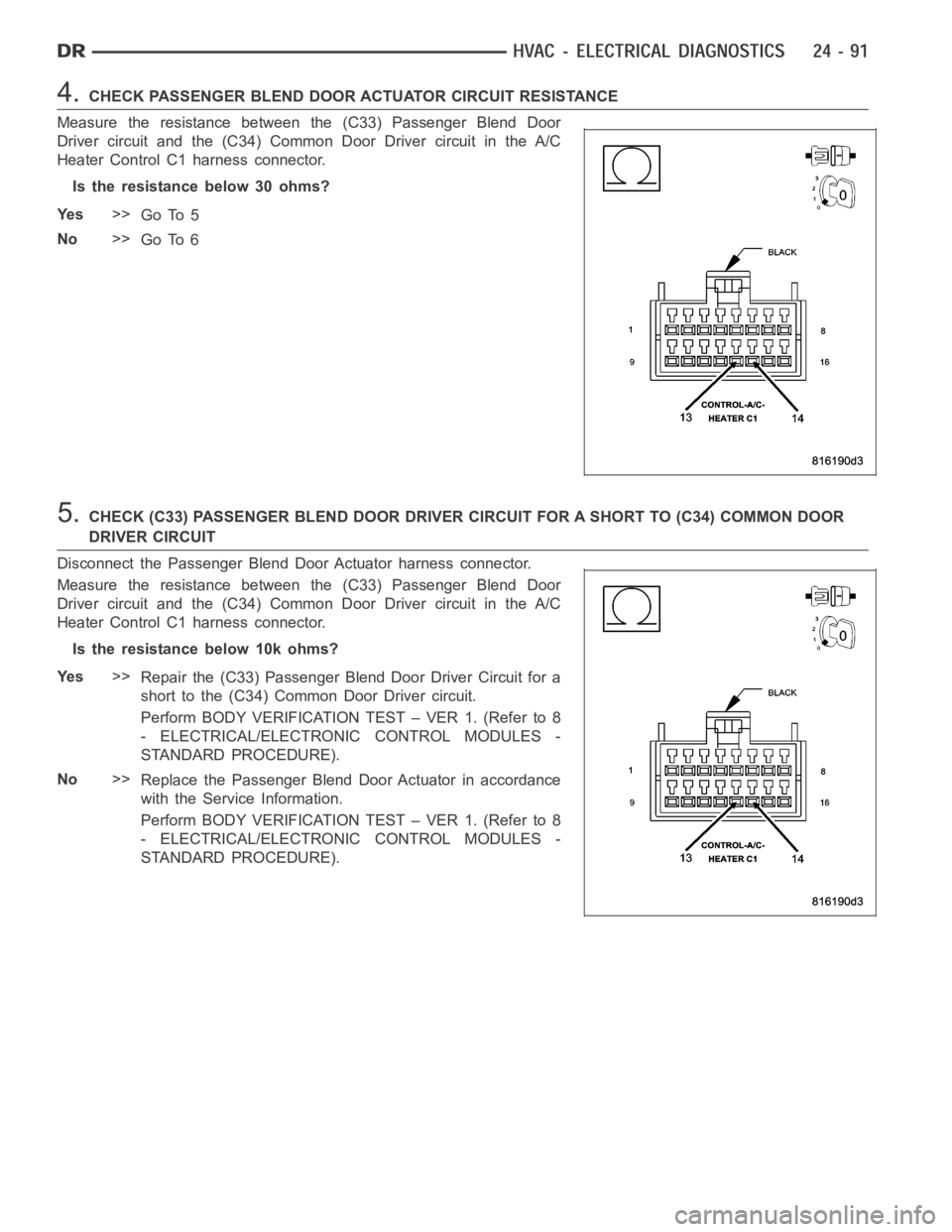
4.CHECK PASSENGER BLEND DOOR ACTUATOR CIRCUIT RESISTANCE
Measure the resistance between the (C33) Passenger Blend Door
Driver circuit and the (C34) Common Door Driver circuit in the A/C
Heater Control C1 harness connector.
Is the resistance below 30 ohms?
Ye s>>
Go To 5
No>>
Go To 6
5.CHECK (C33) PASSENGER BLEND DOOR DRIVER CIRCUIT FOR A SHORT TO (C34) COMMONDOOR
DRIVER CIRCUIT
Disconnect the Passenger Blend Door Actuator harness connector.
Measure the resistance between the (C33) Passenger Blend Door
Driver circuit and the (C34) Common Door Driver circuit in the A/C
Heater Control C1 harness connector.
Istheresistancebelow10kohms?
Ye s>>
Repair the (C33) Passenger Blend Door Driver Circuit for a
short to the (C34) Common Door Driver circuit.
Perform BODY VERIFICATION TEST – VER 1. (Refer to 8
- ELECTRICAL/ELECTRONIC CONTROL MODULES -
STANDARD PROCEDURE).
No>>
Replace the Passenger Blend Door Actuator in accordance
with the Service Information.
Perform BODY VERIFICATION TEST – VER 1. (Refer to 8
- ELECTRICAL/ELECTRONIC CONTROL MODULES -
STANDARD PROCEDURE).
Page 4933 of 5267
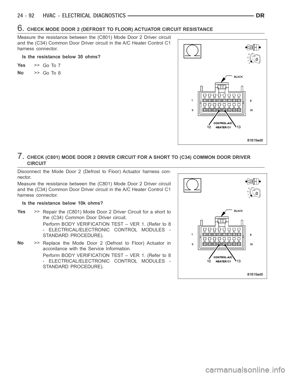
6.CHECK MODE DOOR 2 (DEFROST TO FLOOR) ACTUATOR CIRCUIT RESISTANCE
Measure the resistance between the (C801) Mode Door 2 Driver circuit
and the (C34) Common Door Driver circuit in the A/C Heater Control C1
harness connector.
Is the resistance below 30 ohms?
Ye s>>
Go To 7
No>>
Go To 8
7.CHECK (C801) MODE DOOR 2 DRIVER CIRCUIT FOR A SHORT TO (C34) COMMON DOOR DRIVER
CIRCUIT
Disconnect the Mode Door 2 (Defrost to Floor) Actuator harness con-
nector.
Measure the resistance between the (C801) Mode Door 2 Driver circuit
and the (C34) Common Door Driver circuit in the A/C Heater Control C1
harness connector.
Istheresistancebelow10kohms?
Ye s>>
Repair the (C801) Mode Door 2 Driver Circuit for a short to
the (C34) Common Door Driver circuit.
Perform BODY VERIFICATION TEST – VER 1. (Refer to 8
- ELECTRICAL/ELECTRONIC CONTROL MODULES -
STANDARD PROCEDURE).
No>>
Replace the Mode Door 2 (Defrost to Floor) Actuator in
accordance with the Service Information.
Perform BODY VERIFICATION TEST – VER 1. (Refer to 8
- ELECTRICAL/ELECTRONIC CONTROL MODULES -
STANDARD PROCEDURE).
Page 4934 of 5267
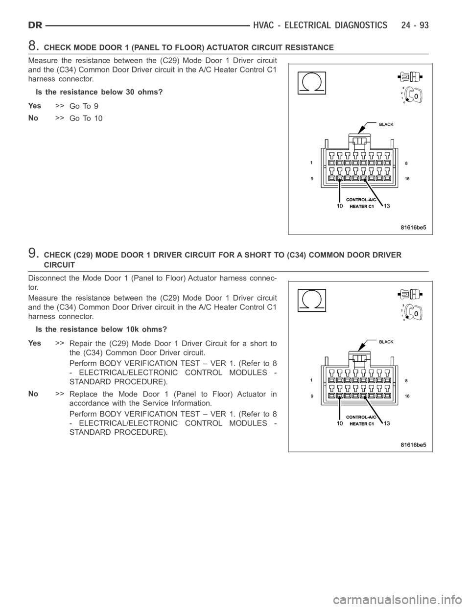
8.CHECK MODE DOOR 1 (PANEL TO FLOOR) ACTUATOR CIRCUIT RESISTANCE
Measure the resistance between the (C29) Mode Door 1 Driver circuit
and the (C34) Common Door Driver circuit in the A/C Heater Control C1
harness connector.
Is the resistance below 30 ohms?
Ye s>>
Go To 9
No>>
Go To 10
9.CHECK (C29) MODE DOOR 1 DRIVER CIRCUIT FOR A SHORT TO (C34) COMMON DOOR DRIVER
CIRCUIT
Disconnect the Mode Door 1 (Panel to Floor) Actuator harness connec-
tor.
Measure the resistance between the (C29) Mode Door 1 Driver circuit
and the (C34) Common Door Driver circuit in the A/C Heater Control C1
harness connector.
Istheresistancebelow10kohms?
Ye s>>
Repair the (C29) Mode Door 1 Driver Circuit for a short to
the (C34) Common Door Driver circuit.
Perform BODY VERIFICATION TEST – VER 1. (Refer to 8
- ELECTRICAL/ELECTRONIC CONTROL MODULES -
STANDARD PROCEDURE).
No>>
Replace the Mode Door 1 (Panel to Floor) Actuator in
accordance with the Service Information.
Perform BODY VERIFICATION TEST – VER 1. (Refer to 8
- ELECTRICAL/ELECTRONIC CONTROL MODULES -
STANDARD PROCEDURE).
Page 4935 of 5267
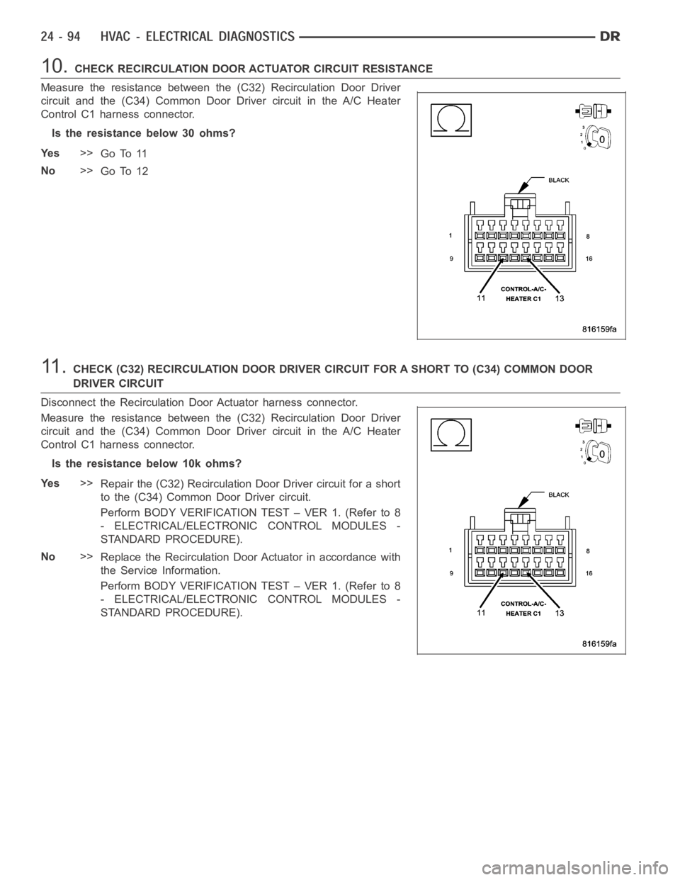
10.CHECK RECIRCULATION DOOR ACTUATOR CIRCUIT RESISTANCE
Measure the resistance between the (C32) Recirculation Door Driver
circuit and the (C34) Common Door Driver circuit in the A/C Heater
Control C1 harness connector.
Is the resistance below 30 ohms?
Ye s>>
Go To 11
No>>
Go To 12
11 .CHECK (C32) RECIRCULATION DOOR DRIVER CIRCUIT FOR A SHORT TO (C34) COMMON DOOR
DRIVER CIRCUIT
Disconnect the Recirculation Door Actuator harness connector.
Measure the resistance between the (C32) Recirculation Door Driver
circuit and the (C34) Common Door Driver circuit in the A/C Heater
Control C1 harness connector.
Istheresistancebelow10kohms?
Ye s>>
Repair the (C32) Recirculation Door Driver circuit for a short
to the (C34) Common DoorDrivercircuit.
Perform BODY VERIFICATION TEST – VER 1. (Refer to 8
- ELECTRICAL/ELECTRONIC CONTROL MODULES -
STANDARD PROCEDURE).
No>>
Replace the Recirculation Door Actuator in accordance with
the Service Information.
Perform BODY VERIFICATION TEST – VER 1. (Refer to 8
- ELECTRICAL/ELECTRONIC CONTROL MODULES -
STANDARD PROCEDURE).
Page 4936 of 5267
12.RUN THE ACTUATOR DTC DETECTION TEST
Reconnect the A/C Heater Control C1 harness connector.
Turn the ignition on.
With the scan tool in HVAC, select System Tests and then select Actuator DTCDetection. When the test is com-
plete, select View DTCs.
Does the scan tool only display: B105F–CLIMATE CONTROL MOTOR(S) COMMON 1 CONTROL CIRCUIT
LOW?
Ye s>>
Replace the A/C Heater Control in accordance with the Service Information.
Perform BODY VERIFICATION TEST – VER 1. (Refer to 8 - ELECTRICAL/ELECTRONIC CONTROL
MODULES - STANDARD PROCEDURE).
No, Other DTC(s) Displayed
Diagnose and repair the other DTC(s). If multiple DTCs are present, beginning with the passenger blend
door, diagnose and repair all short high DTCs and then all short low DTCs. Refer to the Table of Con-
tents in this Section for a complete list of HVAC related symptoms.
No, And No DTCs Displayed
Using the wiring diagram as a guide, inspect the wiring and connectors for conditions causing an inter-
mittent short. Repair as necessary.
Perform BODY VERIFICATION TEST – VER 1. (Refer to 8 - ELECTRICAL/ELECTRONIC CONTROL
MODULES - STANDARD PROCEDURE).