2006 DODGE RAM SRT-10 service
[x] Cancel search: servicePage 4880 of 5267
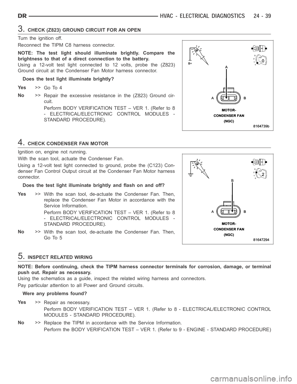
3.CHECK (Z823) GROUND CIRCUIT FOR AN OPEN
Turn the ignition off.
Reconnect the TIPM C8 harness connector.
NOTE: The test light should illuminate brightly. Compare the
brightness to that of a direct connection to the battery.
Using a 12-volt test light connected to 12 volts, probe the (Z823)
Ground circuit at the Condenser Fan Motor harness connector.
Does the test light illuminate brightly?
Ye s>>
Go To 4
No>>
Repair the excessive resistance in the (Z823) Ground cir-
cuit.
Perform BODY VERIFICATION TEST – VER 1. (Refer to 8
- ELECTRICAL/ELECTRONIC CONTROL MODULES -
STANDARD PROCEDURE).
4.CHECK CONDENSER FAN MOTOR
Ignition on, engine not running.
With the scan tool, actuate the Condenser Fan.
Using a 12-volt test light connected to ground, probe the (C123) Con-
denser Fan Control Output circuit at the Condenser Fan Motor harness
connector.
Does the test light illuminate brightly and flash on and off?
Ye s>>
With the scan tool, de-actuate the Condenser Fan. Then,
replace the Condenser Fan Motor in accordance with the
Service Information.
Perform BODY VERIFICATION TEST – VER 1. (Refer to 8
- ELECTRICAL/ELECTRONIC CONTROL MODULES -
STANDARD PROCEDURE).
No>>
With the scan tool, de-actuate the Condenser Fan. Then,
Go To 5
5.INSPECT RELATED WIRING
NOTE: Before continuing, check the TIPM harness connector terminals for corrosion, damage, or terminal
push out. Repair as necessary.
Using the schematics as a guide, inspect the related wiring harness and connectors.
Pay particular attention to all Power and Ground circuits.
Were any problems found?
Ye s>>
Repair as necessary.
Perform BODY VERIFICATION TEST – VER 1. (Refer to 8 - ELECTRICAL/ELECTRONIC CONTROL
MODULES - STANDARD PROCEDURE).
No>>
Replace the TIPM in accordance with the Service Information.
Perform the BODY VERIFICATION TEST – VER 1. (Refer to 9 - ENGINE - STANDARD PROCEDURE)
Page 4882 of 5267
2.CHECK FOR DTCs IN THE A/C HEATER CONTROL MODULE
Turn the ignition on.
With the scan tool, read HVAC DTCs.
Excluding B10B2–A/C Cool Down Test Performance, are any DTCs present in the A/C Heater Control
Module?
Ye s>>
Diagnose and Repair the DTC(s). Refer to the Table of Contents in this Section for a complete list of
HVAC related symptoms. Rerun the Cooldown Test after the repair is complete.
Perform BODY VERIFICATION TEST – VER 1. (Refer to 8 - ELECTRICAL/ELECTRONIC CONTROL
MODULES - STANDARD PROCEDURE).
No>>
Go To 3
3.CHECK FOR DTCs IN THE TIPM
With the scan tool, read TIPM DTCs.
Are any DTCs present in the TIPM?
Ye s>>
Diagnose and Repair the DTC(s). Rerun the Cooldown Test after the repair iscomplete.
Perform BODY VERIFICATION TEST – VER 1. (Refer to 8 - ELECTRICAL/ELECTRONIC CONTROL
MODULES - STANDARD PROCEDURE).
No>>
Go To 4
4.CHECK FOR DTCs IN THE PCM / ECM
With the scan tool, read PCM / ECM DTCs.
Are any DTCs present in the PCM / ECM?
Ye s>>
Diagnose and repair the DTC(s). (Refer to 9 - ENGINE - DIAGNOSIS AND TESTING) for the diagnostic
procedures. Rerun the Cooldown Test after the repair is complete.
Perform BODY VERIFICATION TEST – VER 1. (Refer to 8 - ELECTRICAL/ELECTRONIC CONTROL
MODULES - STANDARD PROCEDURE).
No>>
Refer to the Service Information for additional Cooldown Test related diagnostic information and testing
procedures. Rerun the Cooldown Test after the repair is complete.
Perform BODY VERIFICATION TEST – VER 1. (Refer to 8 - ELECTRICAL/ELECTRONIC CONTROL
MODULES - STANDARD PROCEDURE).
Page 4885 of 5267
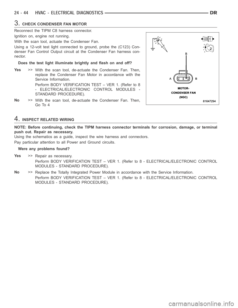
3.CHECK CONDENSER FAN MOTOR
Reconnect the TIPM C8 harness connector.
Ignition on, engine not running.
With the scan tool, actuate the Condenser Fan.
Using a 12-volt test light connected to ground, probe the (C123) Con-
denser Fan Control Output circuit at the Condenser Fan harness con-
nector.
Does the test light illuminate brightly and flash on and off?
Ye s>>
With the scan tool, de-actuate the Condenser Fan. Then,
replace the Condenser Fan Motor in accordance with the
Service Information.
Perform BODY VERIFICATION TEST – VER 1. (Refer to 8
- ELECTRICAL/ELECTRONIC CONTROL MODULES -
STANDARD PROCEDURE).
No>>
With the scan tool, de-actuate the Condenser Fan. Then,
Go To 4
4.INSPECT RELATED WIRING
NOTE: Before continuing, check the TIPM harness connector terminals for corrosion, damage, or terminal
push out. Repair as necessary.
Using the schematics as a guide, inspect the wire harness and connectors.
Pay particular attention to all Power and Ground circuits.
Were any problems found?
Ye s>>
Repair as necessary.
Perform BODY VERIFICATION TEST – VER 1. (Refer to 8 - ELECTRICAL/ELECTRONIC CONTROL
MODULES - STANDARD PROCEDURE).
No>>
Replace the Totally Integrated Power Module in accordance with the Service Information.
Perform BODY VERIFICATION TEST – VER 1. (Refer to 8 - ELECTRICAL/ELECTRONIC CONTROL
MODULES - STANDARD PROCEDURE).
Page 4889 of 5267
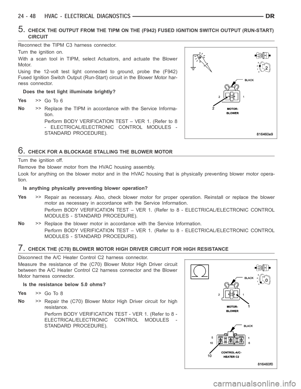
5.CHECK THE OUTPUT FROM THE TIPM ON THE (F942) FUSED IGNITION SWITCH OUTPUT (RUN-START)
CIRCUIT
Reconnect the TIPM C3 harness connector.
Turn the ignition on.
With a scan tool in TIPM, select Actuators, and actuate the Blower
Motor.
Using the 12-volt test light connected to ground, probe the (F942)
Fused Ignition Switch Output (Run-Start) circuit in the Blower Motor har-
ness connector.
Does the test light illuminate brightly?
Ye s>>
Go To 6
No>>
Replace the TIPM in accordance with the Service Informa-
tion.
Perform BODY VERIFICATION TEST – VER 1. (Refer to 8
- ELECTRICAL/ELECTRONIC CONTROL MODULES -
STANDARD PROCEDURE).
6.CHECK FOR A BLOCKAGE STALLING THE BLOWER MOTOR
Turn the ignition off.
Remove the blower motor from the HVAC housing assembly.
Look for anything on the blower motor and in the HVAC housing that is physically preventing blower motor opera-
tion.
Is anything physically preventing blower operation?
Ye s>>
Repair as necessary. Also, check blower motor for proper operation. Reinstall or replace the blower
motor as necessary in accordancewith the Service Information.
Perform BODY VERIFICATION TEST – VER 1. (Refer to 8 - ELECTRICAL/ELECTRONIC CONTROL
MODULES - STANDARD PROCEDURE).
No>>
Replace the blower motor in accordance with the Service Information.
Perform BODY VERIFICATION TEST – VER 1. (Refer to 8 - ELECTRICAL/ELECTRONIC CONTROL
MODULES - STANDARD PROCEDURE).
7.CHECK THE (C70) BLOWER MOTOR HIGH DRIVER CIRCUIT FOR HIGH RESISTANCE
Disconnect the A/C Heater Control C2 harness connector.
Measure the resistance of the (C70) Blower Motor High Driver circuit
between the A/C Heater Control C2 harness connector and the Blower
Motor harness connector.
Is the resistance below 5.0 ohms?
Ye s>>
Go To 8
No>>
Repair the (C70) Blower Motor High Driver circuit for high
resistance.
Perform BODY VERIFICATION TEST - VER 1. (Refer to 8 -
ELECTRICAL/ELECTRONIC CONTROL MODULES -
STANDARD PROCEDURE).
Page 4894 of 5267
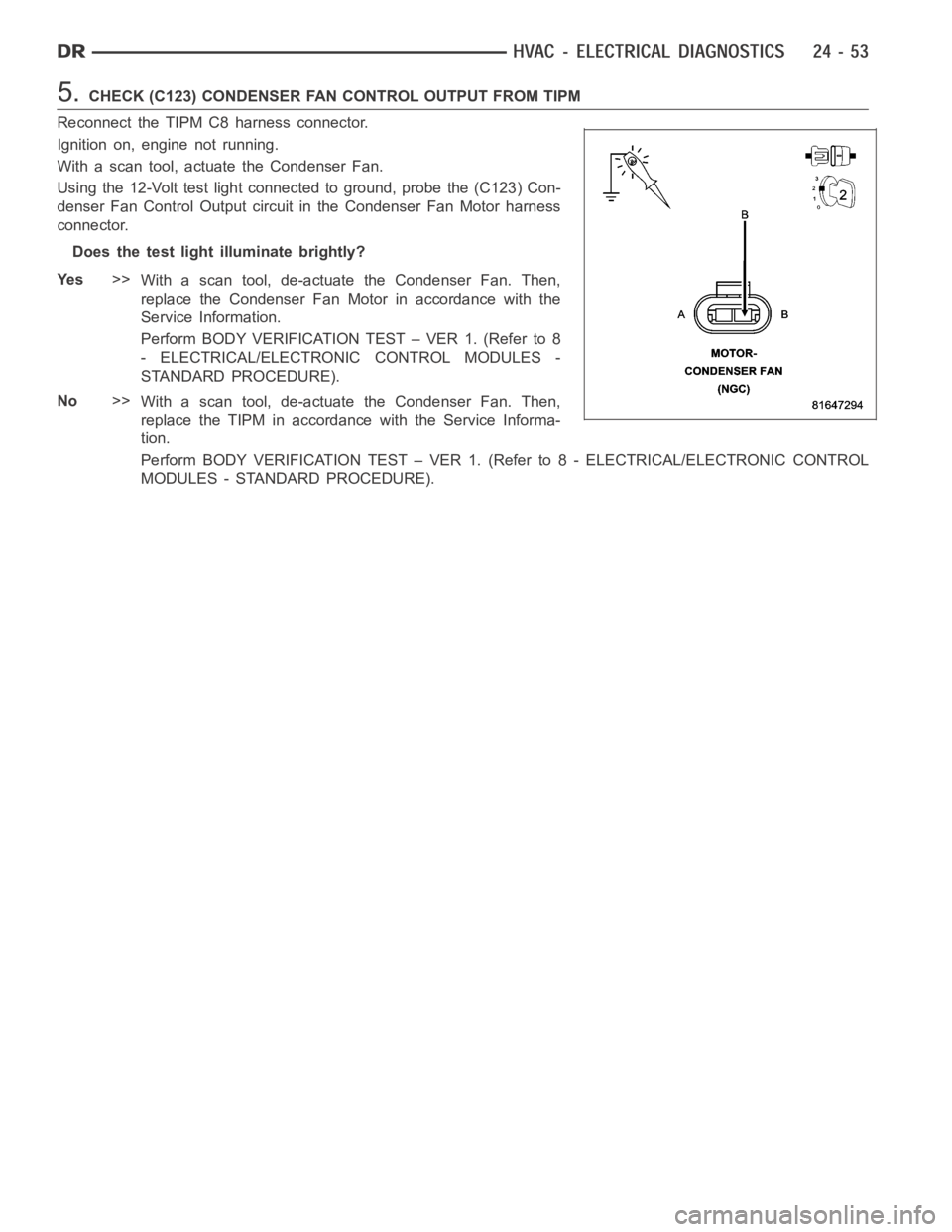
5.CHECK (C123) CONDENSER FAN CONTROL OUTPUT FROM TIPM
Reconnect the TIPM C8 harness connector.
Ignition on, engine not running.
With a scan tool, actuate the Condenser Fan.
Using the 12-Volt test light connected to ground, probe the (C123) Con-
denser Fan Control Output circuit in the Condenser Fan Motor harness
connector.
Does the test light illuminate brightly?
Ye s>>
With a scan tool, de-actuate the Condenser Fan. Then,
replace the Condenser Fan Motor in accordance with the
Service Information.
Perform BODY VERIFICATION TEST – VER 1. (Refer to 8
- ELECTRICAL/ELECTRONIC CONTROL MODULES -
STANDARD PROCEDURE).
No>>
With a scan tool, de-actuate the Condenser Fan. Then,
replace the TIPM in accordance with the Service Informa-
tion.
Perform BODY VERIFICATION TEST – VER 1. (Refer to 8 - ELECTRICAL/ELECTRONIC CONTROL
MODULES - STANDARD PROCEDURE).
Page 4896 of 5267
When Monitored:
With the ignition on.
Set Condition:
If the Totally Integrated Power Module (TIPM) detects an excessive current draw on the (F942) Fused Ignition
Switch Output (Run-Start) circuit for 20 micro seconds when blower motor operation is requested.
Possible Causes
(F942) FUSED IGNITION SWITCH OUTPUT (RUN-START) CIRCUIT SHORTED TO GROUND
BLOWER MOTOR
TIPM
Diagnostic Test
1.VERIFY DTC IS ACTIVE
Turn the blower control switch to off.
Turn the ignition off, wait 10 seconds, and turn the ignition on.
With the scan tool, erase TIPM DTCs.
Turn the ignition off, wait 10 seconds, and turn the ignition on.
Turn the blower control switch to on.
With the scan tool, read TIPM DTCs.
Does this DTC reset?
Ye s>>
Go To 2
No>>
Check for an intermittent condition by inspecting the related wiring harness for chafed, pierced, pinched,
and partially broken wires. Also, inspect the related connectors for broken, bent, corroded, and contam-
inated terminals.
Perform BODY VERIFICATION TEST – VER 1. (Refer to 8 - ELECTRICAL/ELECTRONIC CONTROL
MODULES - STANDARD PROCEDURE).
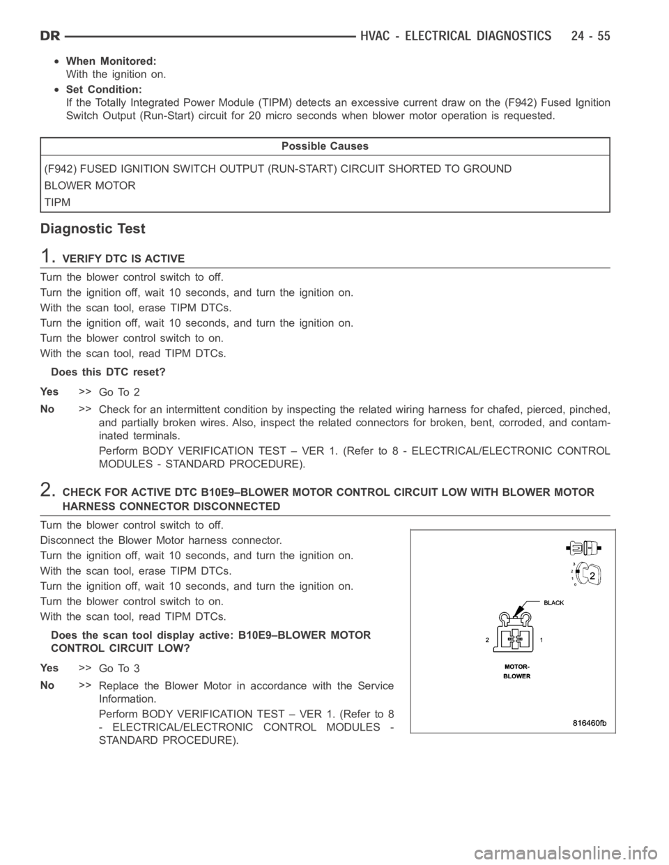
2.CHECK FOR ACTIVE DTC B10E9–BLOWER MOTOR CONTROL CIRCUIT LOW WITH BLOWER MOTOR
HARNESS CONNECTOR DISCONNECTED
Turn the blower control switch to off.
Disconnect the Blower Motor harness connector.
Turn the ignition off, wait 10 seconds, and turn the ignition on.
With the scan tool, erase TIPM DTCs.
Turn the ignition off, wait 10 seconds, and turn the ignition on.
Turn the blower control switch to on.
With the scan tool, read TIPM DTCs.
Does the scan tool display active: B10E9–BLOWER MOTOR
CONTROL CIRCUIT LOW?
Ye s>>
Go To 3
No>>
Replace the Blower Motor in accordance with the Service
Information.
Perform BODY VERIFICATION TEST – VER 1. (Refer to 8
- ELECTRICAL/ELECTRONIC CONTROL MODULES -
STANDARD PROCEDURE).
Page 4897 of 5267
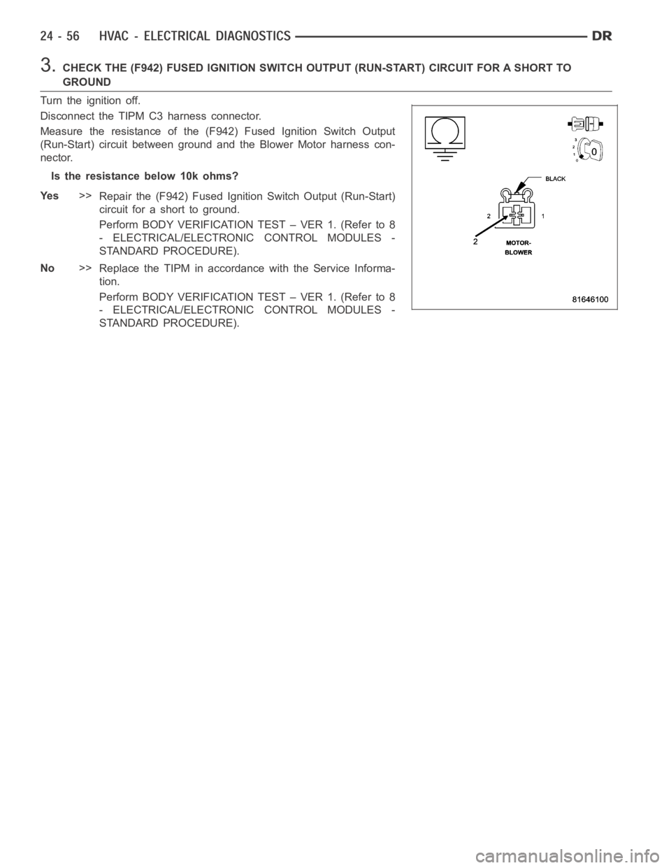
3.CHECK THE (F942) FUSED IGNITION SWITCH OUTPUT (RUN-START) CIRCUIT FOR A SHORT TO
GROUND
Turn the ignition off.
Disconnect the TIPM C3 harness connector.
Measure the resistance of the (F942) Fused Ignition Switch Output
(Run-Start) circuit between ground and the Blower Motor harness con-
nector.
Istheresistancebelow10kohms?
Ye s>>
Repair the (F942) Fused Ignition Switch Output (Run-Start)
circuit for a short to ground.
Perform BODY VERIFICATION TEST – VER 1. (Refer to 8
- ELECTRICAL/ELECTRONIC CONTROL MODULES -
STANDARD PROCEDURE).
No>>
Replace the TIPM in accordance with the Service Informa-
tion.
Perform BODY VERIFICATION TEST – VER 1. (Refer to 8
- ELECTRICAL/ELECTRONIC CONTROL MODULES -
STANDARD PROCEDURE).
Page 4899 of 5267
>>
Diagnose and repair the DTC(s). If multiple DTCs are present, beginning with the common circuit, diag-
nose and repair all short high DTCs first and then all short low DTCs. Refer to the Table of Contents in
this Section for a complete list of HVAC related symptoms.
No>>
Go To 4
4.INSPECT ACTUATOR & HOUSING ASSEMBLY FOR A CONDITION CAUSING THE DOOR TO SEIZE OR
BIND
Turn the ignition off.
Inspect the actuator, linkage, and housing assembly for a condition causing the door to seize or bind.
Are there any physical or mechanical problems with the door, housing, linkage, or actuator?
Ye s>>
Repair as necessary in accordance with the Service Information.
Perform BODY VERIFICATION TEST – VER 1. (Refer to 8 - ELECTRICAL/ELECTRONIC CONTROL
MODULES - STANDARD PROCEDURE).
No>>
Go To 5
5.CHECK MODE 2 (DEFROST TO FLOOR) DOOR TRAVEL
Remove the Mode Door 2 (Defrost to Floor) Actuator from the A/C Heater Housing Assembly.
By hand, attempt to rotate the door in both directions. The door should operate smoothly in both directions over
approximately 103 degrees of travel.
Does the door operate smoothly in both directions over approximately 103 degrees of travel?
Ye s>>
Replace the Mode Door 2 (Defrost to Floor) Actuator in accordance with the Service Information. Then,
Go To 6.
No>>
Repair as necessary in accordance with the Service Information.
Perform BODY VERIFICATION TEST – VER 1. (Refer to 8 - ELECTRICAL/ELECTRONIC CONTROL
MODULES - STANDARD PROCEDURE).
6.RUN ACTUATOR CALIBRATION TEST
Turn the ignition on.
With the scan tool, select System Tests and then select Actuator Calibration Test. When the test is complete, select
View DTCs.
Does the scan tool display: B104A–FLOOR/DEFROST MODE DOOR TRAVEL RANGE TOOSMALL?
Ye s>>
Replace the A/C Heater Control in accordance with the Service Information.
Perform BODY VERIFICATION TEST – VER 1. (Refer to 8 - ELECTRICAL/ELECTRONIC CONTROL
MODULES - STANDARD PROCEDURE).
No>>
Perform BODY VERIFICATION TEST – VER 1. (Refer to 8 - ELECTRICAL/ELECTRONIC CONTROL
MODULES - STANDARD PROCEDURE).