2006 DODGE RAM SRT-10 service
[x] Cancel search: servicePage 4264 of 5267
page page
TRANSFER CASE - NV273 - SERVICE
INFORMATION
DESCRIPTION ............................. 1744
OPERATION ............................... 1744
DIAGNOSIS AND TESTING - TRANSFER
CASE - NV273 ............................ 1745
REMOVAL ................................. 1746
DISASSEMBLY ............................. 1746
CLEANING ................................. 1760
INSPECTION ............................... 1760
ASSEMBLY . ............................... 1763
INSTALLATION ............................. 1780
SPECIFICATIONS
TRANSFER CASE - NV273 ................ 1781
SPECIAL TOOLS
TRANSFER CASE NV271/NV273 ........... 1782
BOOT-EXTENSION HOUSING SEAL AND DUST
REMOVAL ................................. 1784INSTALLATION ............................. 1784
FLUID
STANDARD PROCEDURE - FLUID DRAIN AND
REFILL ................................... 1785
SEAL-FRONT OUTPUT SHAFT
REMOVAL ................................. 1786
INSTALLATION ............................. 1786
SENSOR-MODE
DESCRIPTION ............................. 1787
OPERATION ............................... 1787
SWITCH-SELECTOR
DESCRIPTION ............................. 1789
OPERATION ............................... 1789
MOTOR-SHIFT
DESCRIPTION ............................. 1791
OPERATION ............................... 1791
REMOVAL ................................. 1791
INSTALLATION ............................. 1791
Page 4265 of 5267
TRANSFER CASE - NV273 - SERVICE INFORMATION
DESCRIPTION
The NV273 is an electronically controlled part-time transfer case with a low range gear reduction system. The
NV273 has three operating ranges plus a NEUTRAL position. The low range system provides a gear reduction ratio
for increased low speed torque capability.
The geartrain is mounted in two aluminum case halves attached with bolts. The mainshaft front and rear bearings
are mounted in aluminum case halves.
OPERATING RANGES
Transfer case operating ranges are:
2WD (2-wheel drive).
4HI (4-wheel drive).
4LO (4-wheel drive low range).
NEUTRAL.
The 2WD range is for use on any road surface at any time.
The 4HI and 4LO ranges are for off road use only. They are not for use on hard surface roads. The only exception
being when the road surface is wet or slippery or covered by ice and snow.
The low range reduction gear system is operative in 4LO range only. This range is for extra pulling power in off road
situations. Low range reduction ratio is 2.72:1.
SHIFT MECHANISM
Operating ranges are selected with a dash mounted shift selector switch. The shift selector switch provides a input
to the Transfer Case Control Module (TCCM) to indicate the driver’s desireto change operating ranges. The TCCM
uses this input, along with input from the transfer case mounted mode sensor and information from the vehicle’s
bus, to determine if a shift is permitted. If the TCCM decides the shift is permitted, the TCCM controls the shift
motor, mounted to the exterior of the transfer case, to perform the shift.
IDENTIFICATION
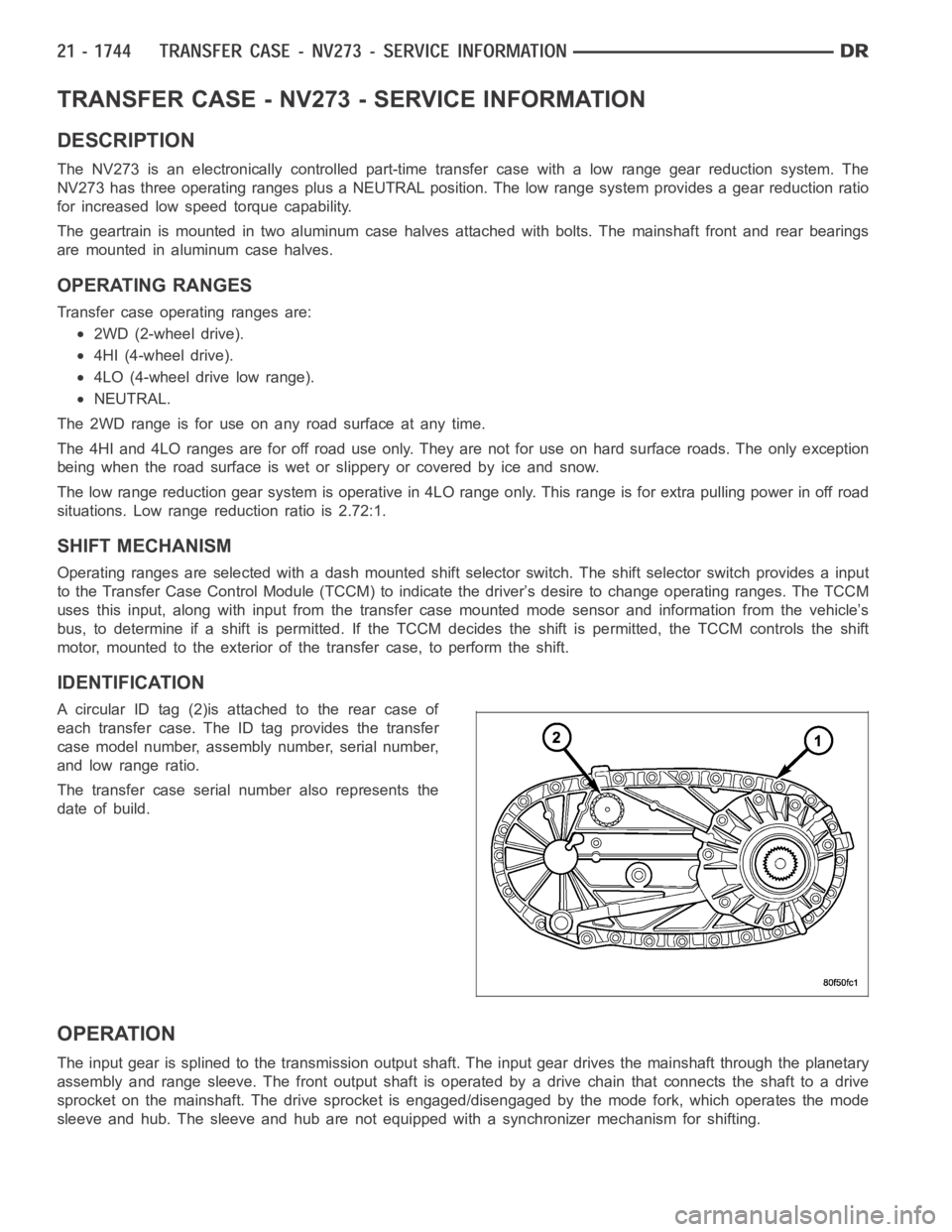
A circular ID tag (2)is attached to the rear case of
each transfer case. The ID tag provides the transfer
case model number, assembly number, serial number,
and low range ratio.
The transfer case serial number also represents the
date of build.
OPERATION
The input gear is splined to the transmission output shaft. The input gear drives the mainshaft through the planetary
assembly and range sleeve. The front output shaft is operated by a drive chain that connects the shaft to a drive
sprocket on the mainshaft. The drive sprocket is engaged/disengaged by themodefork,whichoperatesthemode
sleeve and hub. The sleeve and hub are not equipped with a synchronizer mechanism for shifting.
Page 4283 of 5267
SHIFT FORKS/HUBS/SLEEVES
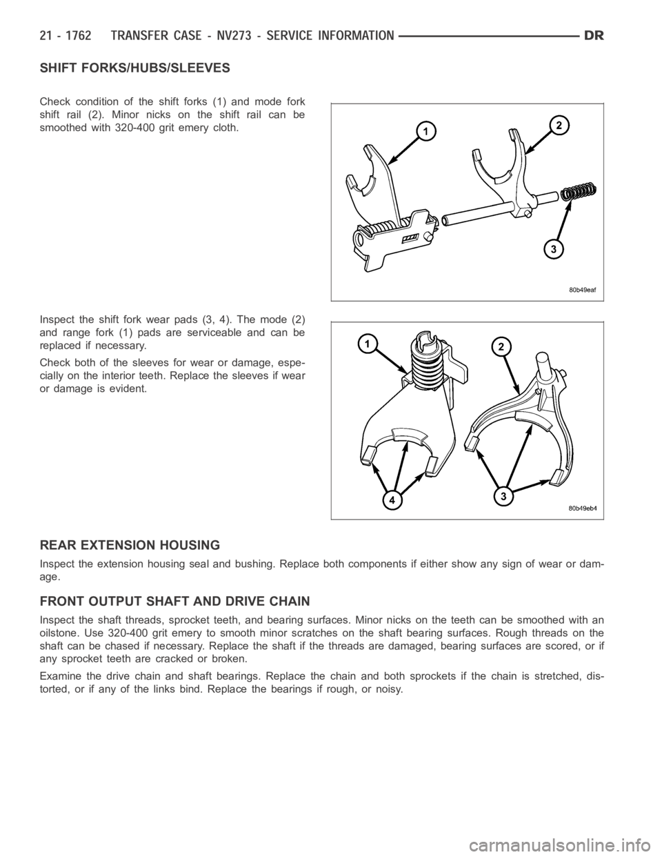
Check condition of the shift forks (1) and mode fork
shift rail (2). Minor nicks on the shift rail can be
smoothed with 320-400 grit emery cloth.
Inspect the shift fork wear pads (3, 4). The mode (2)
and range fork (1) pads are serviceable and can be
replaced if necessary.
Check both of the sleeves for wear or damage, espe-
cially on the interior teeth. Replace the sleeves if wear
or damage is evident.
REAR EXTENSION HOUSING
Inspect the extension housing seal and bushing. Replace both components if either show any sign of wear or dam-
age.
FRONT OUTPUT SHAFT AND DRIVE CHAIN
Inspect the shaft threads, sprocket teeth, and bearing surfaces. Minor nicksontheteethcanbesmoothedwithan
oilstone. Use 320-400 grit emery to smooth minor scratches on the shaft bearing surfaces. Rough threads on the
shaft can be chased if necessary. Replace the shaft if the threads are damaged, bearing surfaces are scored, or if
any sprocket teeth are cracked or broken.
Examine the drive chain and shaft bearings. Replace the chain and both sprockets if the chain is stretched, dis-
torted, or if any of the links bind. Replace the bearings if rough, or noisy.
Page 4284 of 5267
LOW RANGE ANNULUS GEAR
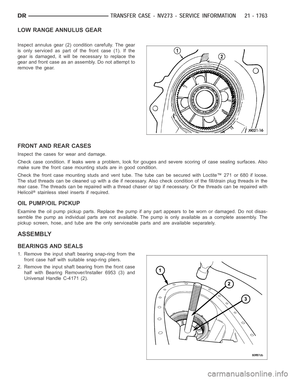
Inspect annulus gear (2) condition carefully. The gear
is only serviced as part of the front case (1). If the
gear is damaged, it will be necessary to replace the
gear and front case as an assembly. Do not attempt to
remove the gear.
FRONT AND REAR CASES
Inspect the cases for wear and damage.
Check case condition. If leaks were a problem, look for gouges and severe scoring of case sealing surfaces. Also
make sure the front case mounting studs are in good condition.
Check the front case mounting studs and vent tube. The tube can be secured with Loctite™ 271 or 680 if loose.
Thestudthreadscanbecleanedupwithadieifnecessary.Alsocheckcondition of the fill/drain plug threads in the
rear case. The threads can be repaired with a thread chaser or tap if necessary. Or the threads can be repaired with
Helicoil
stainless steel inserts if required.
OIL PUMP/OIL PICKUP
Examine the oil pump pickup parts. Replace the pump if any part appears to beworn or damaged. Do not disas-
semble the pump as individual parts are not available. The pump is only available as a complete assembly. The
pickup screen, hose, and tube are the only serviceable parts and are available separately.
ASSEMBLY
BEARINGS AND SEALS
1. Remove the input shaft bearing snap-ring from the
front case half with suitable snap-ring pliers.
2. Remove the input shaft bearing from the front case
half with Bearing Remover/Installer 6953 (3) and
Universal Handle C-4171 (2).
Page 4317 of 5267
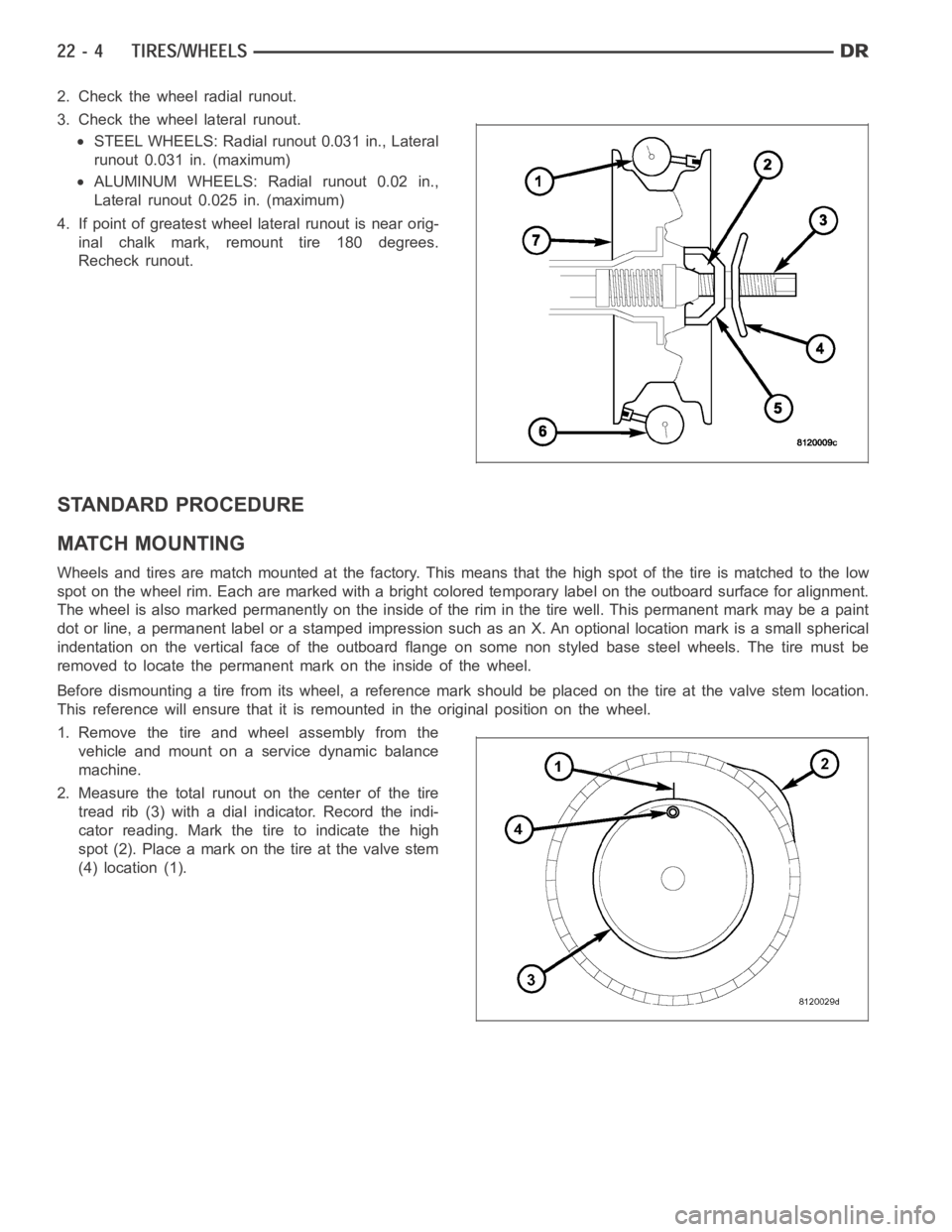
2. Check the wheel radial runout.
3. Check the wheel lateral runout.
STEEL WHEELS: Radial runout 0.031 in., Lateral
runout 0.031 in. (maximum)
ALUMINUM WHEELS: Radial runout 0.02 in.,
Lateral runout 0.025 in. (maximum)
4. If point of greatest wheel lateral runout is near orig-
inal chalk mark, remount tire 180 degrees.
Recheck runout.
STANDARD PROCEDURE
MATCH MOUNTING
Wheels and tires are match mounted at the factory. This means that the high spot of the tire is matched to the low
spot on the wheel rim. Each are marked with a bright colored temporary labelon the outboard surface for alignment.
The wheel is also marked permanently on the inside of the rim in the tire well. This permanent mark may be a paint
dot or line, a permanent label or a stamped impression such as an X. An optional location mark is a small spherical
indentation on the vertical face of the outboard flange on some non styled base steel wheels. The tire must be
removed to locate the permanent mark on the inside of the wheel.
Before dismounting a tire from its wheel, a reference mark should be placedon the tire at the valve stem location.
This reference will ensure that it is remounted in the original position onthe wheel.
1. Remove the tire and wheel assembly from the
vehicle and mount on a service dynamic balance
machine.
2. Measure the total runout on the center of the tire
tread rib (3) with a dial indicator. Record the indi-
cator reading. Mark the tire to indicate the high
spot (2). Place a mark on the tire at the valve stem
(4) location (1).
Page 4318 of 5267
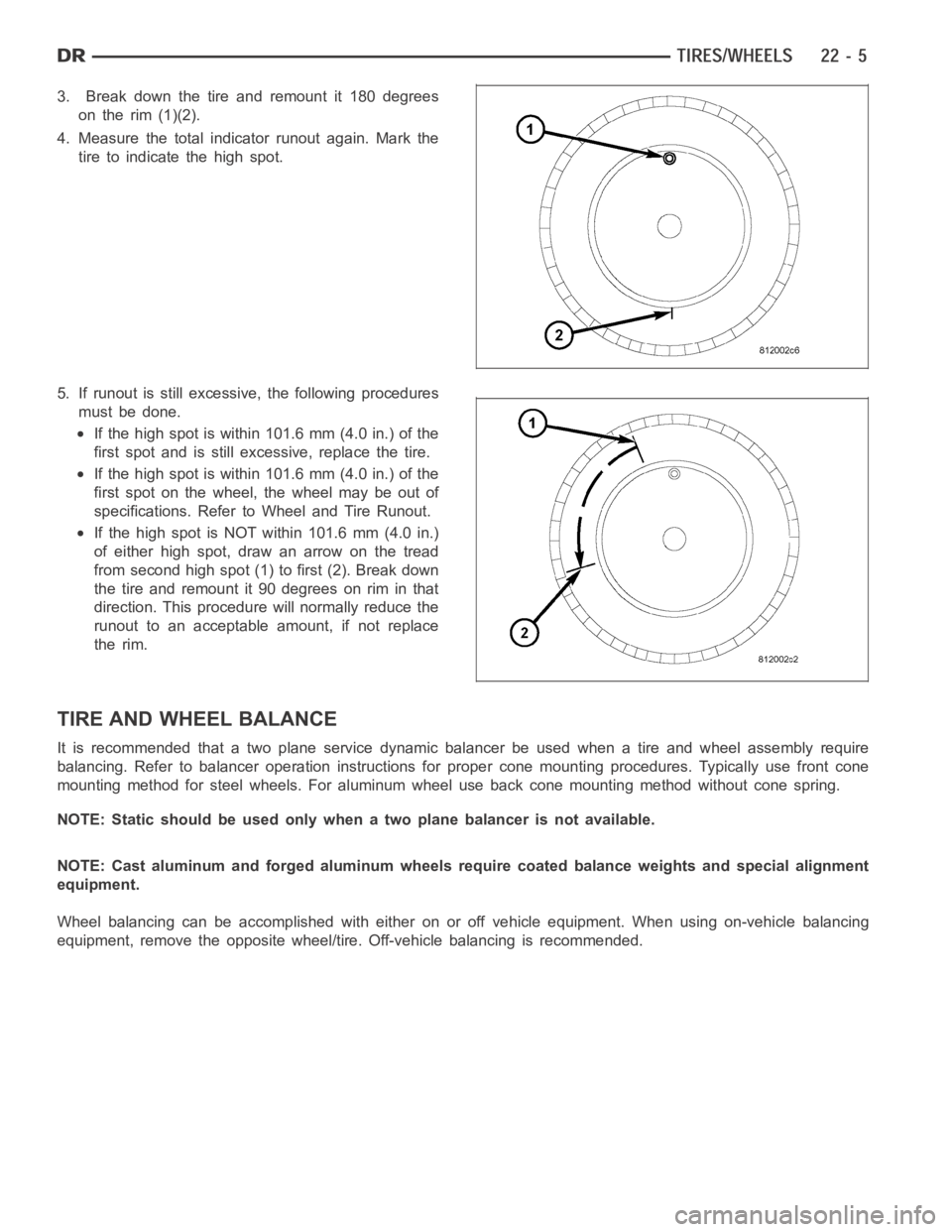
3. Break down the tire and remount it 180 degrees
on the rim (1)(2).
4. Measure the total indicator runout again. Mark the
tire to indicate the high spot.
5. If runout is still excessive, the following procedures
must be done.
If the high spot is within 101.6 mm (4.0 in.) of the
first spot and is still excessive, replace the tire.
If the high spot is within 101.6 mm (4.0 in.) of the
first spot on the wheel, the wheel may be out of
specifications. Refer to Wheel and Tire Runout.
IfthehighspotisNOTwithin101.6mm(4.0in.)
of either high spot, draw an arrow on the tread
from second high spot (1) to first (2). Break down
the tire and remount it 90 degrees on rim in that
direction. This procedure will normally reduce the
runout to an acceptable amount, if not replace
the rim.
TIRE AND WHEEL BALANCE
It is recommended that a two plane service dynamic balancer be used when a tire and wheel assembly require
balancing. Refer to balancer operation instructions for proper cone mounting procedures. Typically use front cone
mounting method for steel wheels. For aluminum wheel use back cone mounting method without cone spring.
NOTE: Static should be used only when a two plane balancer is not available.
NOTE: Cast aluminum and forged aluminum wheels require coated balance weights and special alignment
equipment.
Wheel balancing can be accomplished with either on or off vehicle equipment. When using on-vehicle balancing
equipment, remove the opposite wheel/tire. Off-vehicle balancing is recommended.
Page 4329 of 5267
WHEEL DESIGN
The rim size is on the vehicle safety certification label
located on the drivers door shut face. The size of the
rim is determined by the drivetrain package. Original
equipment wheels/rims are designed for operation up
to the specified maximum vehicle capacity.
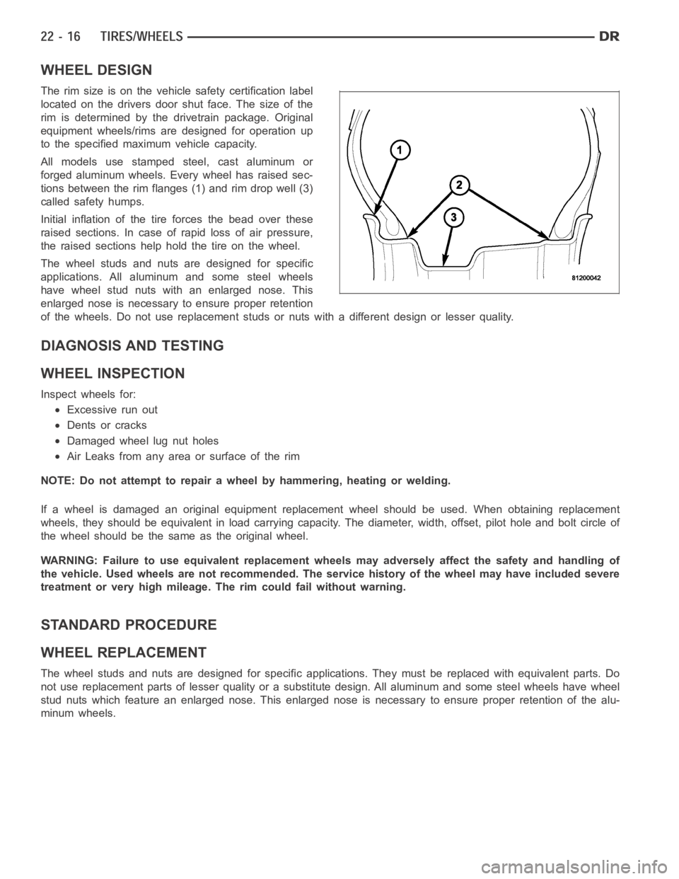
All models use stamped steel, cast aluminum or
forged aluminum wheels. Every wheel has raised sec-
tions between the rim flanges (1) and rim drop well (3)
called safety humps.
Initial inflation of the tire forces the bead over these
raised sections. In case of rapid loss of air pressure,
the raised sections help hold the tire on the wheel.
The wheel studs and nuts are designed for specific
applications. All aluminum and some steel wheels
have wheel stud nuts with an enlarged nose. This
enlarged nose is necessary to ensure proper retention
of the wheels. Do not use replacement studs or nuts with a different design orlesserquality.
DIAGNOSIS AND TESTING
WHEEL INSPECTION
Inspect wheels for:
Excessive run out
Dents or cracks
Damaged wheel lug nut holes
Air Leaks from any area or surface of the rim
NOTE: Do not attempt to repair a wheel by hammering, heating or welding.
If a wheel is damaged an original equipment replacement wheel should be used. When obtaining replacement
wheels, they should be equivalent in load carrying capacity. The diameter, width, offset, pilot hole and bolt circle of
the wheel should be the same as the original wheel.
WARNING: Failure to use equivalent replacement wheels may adversely affect the safety and handling of
the vehicle. Used wheels are not recommended. The service history of the wheel may have included severe
treatment or very high mileage. The rim could fail without warning.
STANDARD PROCEDURE
WHEEL REPLACEMENT
The wheel studs and nuts are designed for specific applications. They mustbe replaced with equivalent parts. Do
not use replacement parts of lesser quality or a substitute design. All aluminum and some steel wheels have wheel
stud nuts which feature an enlarged nose. This enlarged nose is necessary to ensure proper retention of the alu-
minum wheels.
Page 4331 of 5267
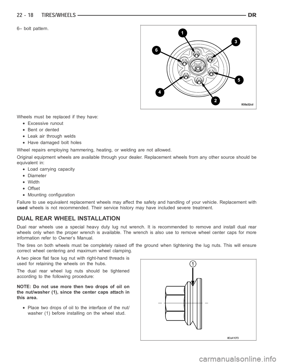
6– bolt pattern.
Wheels must be replaced if they have:
Excessive runout
Bent or dented
Leak air through welds
Have damaged bolt holes
Wheel repairs employing hammering, heating, or welding are not allowed.
Original equipment wheels are available through your dealer. Replacement wheels from any other source should be
equivalent in:
Load carrying capacity
Diameter
Width
Offset
Mounting configuration
Failure to use equivalent replacement wheels may affect the safety and handling of your vehicle. Replacement with
usedwheels is not recommended. Their service history may have included severetreatment.
DUAL REAR WHEELINSTALLATION
Dual rear wheels use a special heavy duty lug nut wrench. It is recommended to remove and install dual rear
wheels only when the proper wrench is available. The wrench is also use to remove wheel center caps for more
information refer to Owner’s Manual.
The tires on both wheels must be completely raised off the ground when tightening the lug nuts. This will ensure
correct wheel centering and maximum wheel clamping.
A two piece flat face lug nut with right-hand threads is
used for retaining the wheels on the hubs.
The dual rear wheel lug nuts should be tightened
according to the following procedure:
NOTE: Do not use more then two drops of oil on
the nut/washer (1), since the center caps attach in
this area.
Place two drops of oil to the interface of the nut/
washer (1) before installing on the wheel stud.