Page 4084 of 5267
page page
TRANSFER CASE - NV241 GENII - SERVICE
INFORMATION
DESCRIPTION ............................. 1564
OPERATION ............................... 1564
DIAGNOSIS AND TESTING - TRANSFER
CASE - NV241 GENII ...................... 1565
REMOVAL ................................. 1566
DISASSEMBLY ............................. 1566
CLEANING ................................. 1578
INSPECTION ............................... 1579
ASSEMBLY . ............................... 1581
INSTALLATION ............................. 1594
SPECIFICATIONS
TRANSFER CASE - NV241 GENII .......... 1594
SPECIAL TOOLS
TRANSFER CASE - NV241/NV243 ......... 1596SEAL-EXTENSION HOUSING
REMOVAL ................................. 1598
INSTALLATION ............................. 1598
FLUID
STANDARD PROCEDURE - FLUID DRAIN AND
REFILL ................................... 1599
FRONTOUTPUTSHAFTSEAL
REMOVAL ................................. 1600
INSTALLATION ............................. 1601
LEVER-SHIFT
REMOVAL ................................. 1602
INSTALLATION ............................. 1603
ADJUSTMENTS
ADJUSTMENT - SHIFT LEVER............. 1604
Page 4085 of 5267
TRANSFER CASE - NV241 GENII - SERVICE INFORMATION
DESCRIPTION
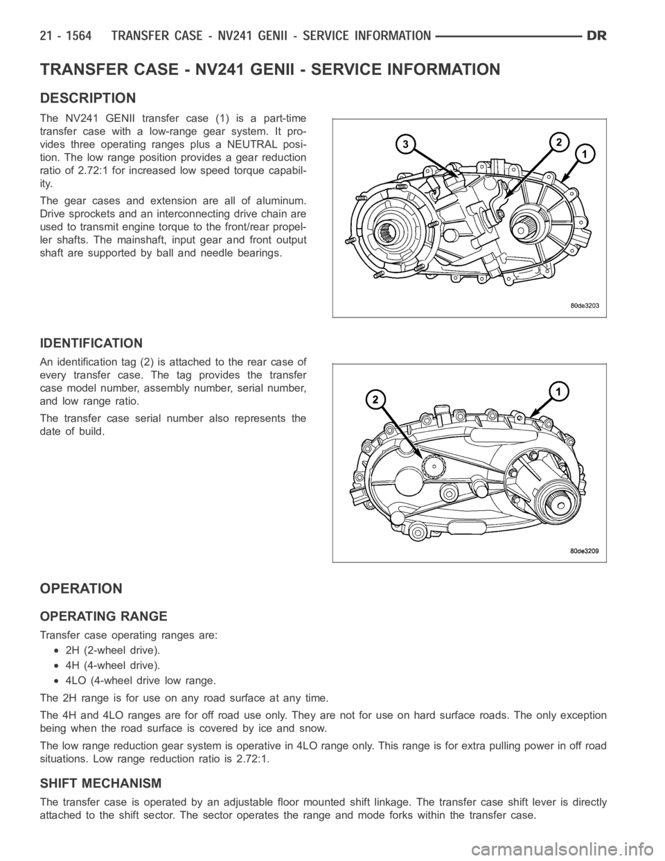
The NV241 GENII transfer case (1) is a part-time
transfer case with a low-range gear system. It pro-
vides three operating ranges plus a NEUTRAL posi-
tion. The low range position provides a gear reduction
ratio of 2.72:1 for increased low speed torque capabil-
ity.
The gear cases and extension are all of aluminum.
Drive sprockets and an interconnecting drive chain are
used to transmit engine torque to the front/rear propel-
ler shafts. The mainshaft, input gear and front output
shaft are supported by ball and needle bearings.
IDENTIFICATION
An identification tag (2) is attached to the rear case of
every transfer case. The tag provides the transfer
case model number, assembly number, serial number,
and low range ratio.
The transfer case serial number also represents the
date of build.
OPERATION
OPERATING RANGE
Transfer case operating ranges are:
2H (2-wheel drive).
4H (4-wheel drive).
4LO (4-wheel drive low range.
The 2H range is for use on any road surface at any time.
The 4H and 4LO ranges are for off road use only. They are not for use on hard surface roads. The only exception
being when the road surface is covered by ice and snow.
The low range reduction gear system is operative in 4LO range only. This range is for extra pulling power in off road
situations. Low range reduction ratio is 2.72:1.
SHIFT MECHANISM
The transfer case is operated by an adjustable floor mounted shift linkage. The transfer case shift lever is directly
attached to the shift sector. The sector operates the range and mode forks within the transfer case.
Page 4101 of 5267
SHIFT FORKS/HUBS/SLEEVES
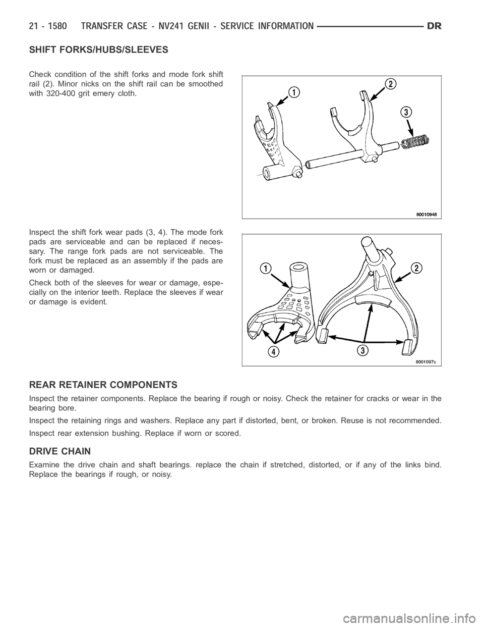
Check condition of the shift forks and mode fork shift
rail (2). Minor nicks on the shift rail can be smoothed
with 320-400 grit emery cloth.
Inspect the shift fork wear pads (3, 4). The mode fork
pads are serviceable and can be replaced if neces-
sary. The range fork pads are not serviceable. The
fork must be replaced as an assembly if the pads are
worn or damaged.
Check both of the sleeves for wear or damage, espe-
cially on the interior teeth. Replace the sleeves if wear
or damage is evident.
REAR RETAINER COMPONENTS
Inspect the retainer components. Replace the bearing if rough or noisy. Check the retainer for cracks or wear in the
bearing bore.
Inspect the retaining rings and washers. Replace any part if distorted, bent, or broken. Reuse is not recommended.
Inspect rear extension bushing. Replace if worn or scored.
DRIVE CHAIN
Examine the drive chain and shaft bearings. replace the chain if stretched, distorted, or if any of the links bind.
Replace the bearings if rough, or noisy.
Page 4102 of 5267
LOW RANGE ANNULUS GEAR
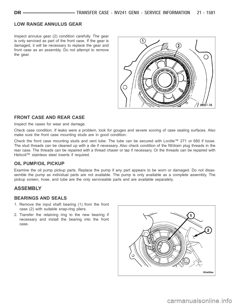
Inspect annulus gear (2) condition carefully. The gear
is only serviced as part of the front case. If the gear is
damaged, it will be necessary to replace the gear and
front case as an assembly. Do not attempt to remove
the gear.
FRONT CASE AND REAR CASE
Inspect the cases for wear and damage.
Check case condition. If leaks were a problem, look for gouges and severe scoring of case sealing surfaces. Also
make sure the front case mounting studs are in good condition.
Check the front case mounting studs and vent tube. The tube can be secured with Loctite™ 271 or 680 if loose.
Thestudthreadscanbecleanedupwithadieifnecessary.Alsocheckcondition of the fill/drain plug threads in the
rear case. The threads can be repaired with a thread chaser or tap if necessary. Or the threads can be repaired with
Helicoil™ stainless steel inserts if required.
OIL PUMP/OIL PICKUP
Examine the oil pump pickup parts. Replace the pump if any part appears to beworn or damaged. Do not disas-
semble the pump as individual parts are not available. The pump is only available as a complete assembly. The
pickup screen, hose, and tube are the only serviceable parts and are available separately.
ASSEMBLY
BEARINGS AND SEALS
1. Remove the input shaft bearing (1) from the front
case (2) with suitable snap-ring pliers.
2. Transfer the retaining ring to the new bearing if
necessary and install the bearing into the front
case.
Page 4126 of 5267
page page
TRANSFER CASE - NV271 - SERVICE
INFORMATION
DESCRIPTION ............................. 1606
OPERATION ............................... 1606
DIAGNOSIS AND TESTING - TRANSFER
CASE - NV271 ............................ 1607
REMOVAL ................................. 1608
DISASSEMBLY ............................. 1608
CLEANING ................................. 1623
INSPECTION ............................... 1623
ASSEMBLY . ............................... 1626
INSTALLATION ............................. 1644
SPECIFICATIONS
TRANSFER CASE - NV271 ................ 1645
SPECIAL TOOLS
TRANSFER CASE NV271/NV273 ........... 1646
BOOT-EXTENSION HOUSING SEAL AND DUST
REMOVAL ................................. 1648INSTALLATION ............................. 1648
FLUID
STANDARD PROCEDURE - FLUID DRAIN AND
REFILL ................................... 1649
SEAL-FRONT OUTPUT SHAFT
REMOVAL ................................. 1650
INSTALLATION ............................. 1650
SENSOR-POSITION
DESCRIPTION ............................. 1651
OPERATION ............................... 1651
REMOVAL ................................. 1651
INSTALLATION ............................. 1652
LEVER-SHIFT
REMOVAL ................................. 1653
INSTALLATION ............................. 1654
ADJUSTMENTS
ADJUSTMENT - SHIFT LEVER............. 1655
Page 4127 of 5267
TRANSFER CASE - NV271 - SERVICE INFORMATION
DESCRIPTION
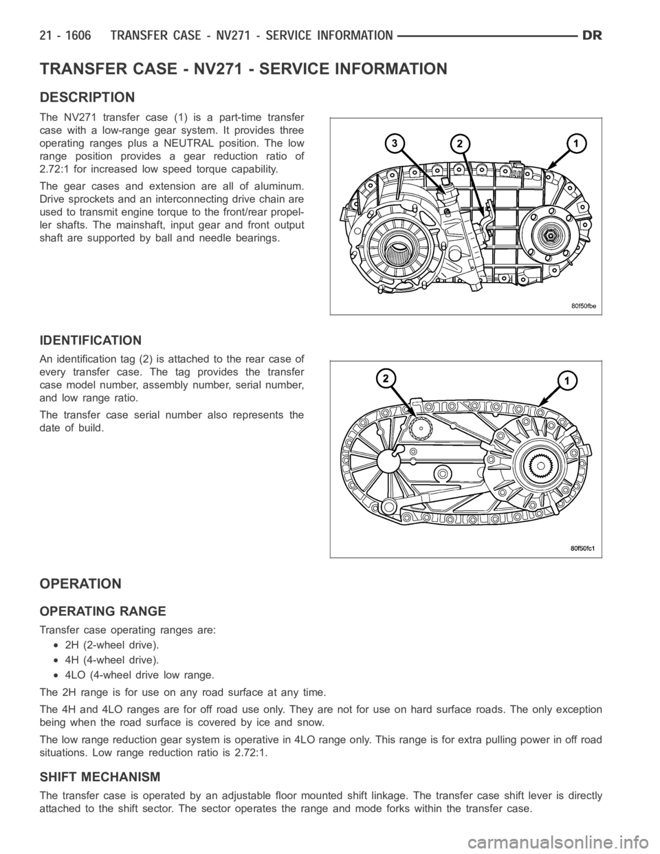
The NV271 transfer case (1) is a part-time transfer
case with a low-range gear system. It provides three
operating ranges plus a NEUTRAL position. The low
range position provides a gear reduction ratio of
2.72:1 for increased low speed torque capability.
The gear cases and extension are all of aluminum.
Drive sprockets and an interconnecting drive chain are
used to transmit engine torque to the front/rear propel-
ler shafts. The mainshaft, input gear and front output
shaft are supported by ball and needle bearings.
IDENTIFICATION
An identification tag (2) is attached to the rear case of
every transfer case. The tag provides the transfer
case model number, assembly number, serial number,
and low range ratio.
The transfer case serial number also represents the
date of build.
OPERATION
OPERATING RANGE
Transfer case operating ranges are:
2H (2-wheel drive).
4H (4-wheel drive).
4LO (4-wheel drive low range.
The 2H range is for use on any road surface at any time.
The 4H and 4LO ranges are for off road use only. They are not for use on hard surface roads. The only exception
being when the road surface is covered by ice and snow.
The low range reduction gear system is operative in 4LO range only. This range is for extra pulling power in off road
situations. Low range reduction ratio is 2.72:1.
SHIFT MECHANISM
The transfer case is operated by an adjustable floor mounted shift linkage. The transfer case shift lever is directly
attached to the shift sector. The sector operates the range and mode forks within the transfer case.
Page 4146 of 5267
SHIFT FORKS/HUBS/SLEEVES
Check condition of the shift forks and mode fork shift
rail (2). Minor nicks on the shift rail can be smoothed
with 320-400 grit emery cloth.
Inspect the shift fork wear pads (3). The mode and
range fork pads are serviceable and can be replaced
if necessary.
Check both of the sleeves for wear or damage, espe-
cially on the interior teeth. Replace the sleeves if wear
or damage is evident.
DRIVE CHAIN
Examine the drive chain and shaft bearings. replace the chain if stretched, distorted, or if any of the links bind.
Replace the bearings if rough, or noisy.
LOW RANGE ANNULUS GEAR
Inspect annulus gear (2) condition carefully. The gear
is only serviced as part of the front case (1). If the
gear is damaged, it will be necessary to replace the
gear and front case as an assembly. Do not attempt to
remove the gear (2)
Page 4147 of 5267
FRONT CASE AND REAR CASE
Inspect the cases for wear and damage.
Check case condition. If leaks were a problem, look for gouges and severe scoring of case sealing surfaces. Also
make sure the front case mounting studs are in good condition.
Check the front case mounting studs and vent tube. The tube can be secured with Loctite™ 271 or 680 if loose.
Thestudthreadscanbecleanedupwithadieifnecessary.Alsocheckcondition of the fill/drain plug threads in the
rear case. The threads can be repaired with a thread chaser or tap if necessary. Or the threads can be repaired with
Helicoil™ stainless steel inserts if required.
OIL PUMP/OIL PICKUP
Examine the oil pump pickup parts. Replace the pump if any part appears to beworn or damaged. Do not disas-
semble the pump as individual parts are not available. The pump is only available as a complete assembly. The
pickup screen, hose, and tube are the only serviceable parts and are available separately.
ASSEMBLY
BEARINGS AND SEALS
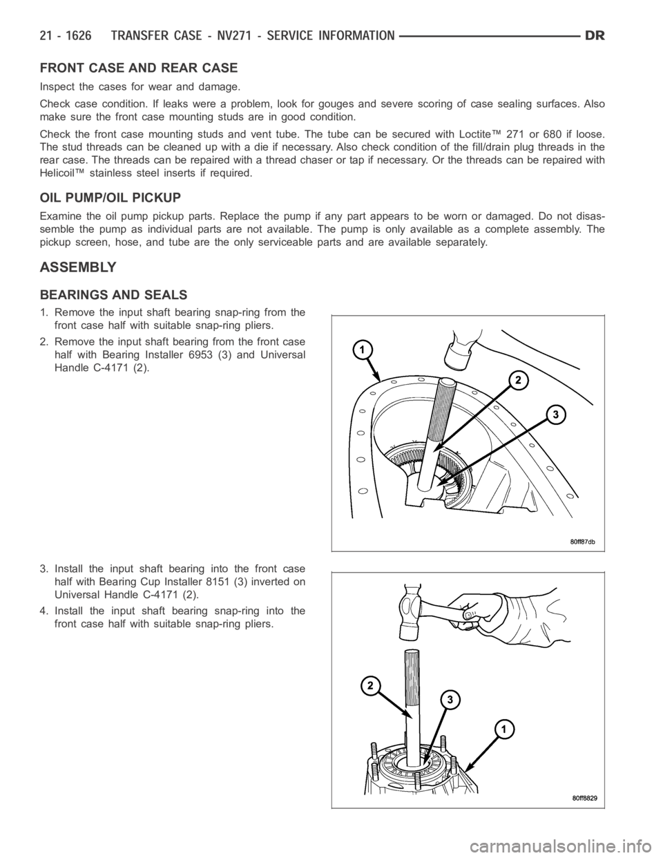
1. Remove the input shaft bearing snap-ring from the
front case half with suitable snap-ring pliers.
2. Remove the input shaft bearing from the front case
half with Bearing Installer 6953 (3) and Universal
Handle C-4171 (2).
3. Install the input shaft bearing into the front case
half with Bearing Cup Installer 8151 (3) inverted on
Universal Handle C-4171 (2).
4. Install the input shaft bearing snap-ring into the
front case half with suitable snap-ring pliers.