2006 DODGE RAM SRT-10 service
[x] Cancel search: servicePage 3921 of 5267
d. Push overdrive piston into position in retainer.
e. Verify that the locating lugs entered the lug bores in the retainer.
6. Install intermediate shaft spacer on intermediate shaft.
7. Install overdrive piston thrust plate on overdrive piston.
8. Install overdrive piston thrust bearing on overdrive piston.
9. Install transmission speed sensorand o-ring seal in overdrive case.
INSTALLATION
1. Be sure overdrive unit Alignment Tool 6227-2 is
fully seated before moving unit. If tool is not seated
and gear splines rotate out of alignment, overdrive
unit will have to be disassembled in order to realign
splines.
2. If overdrive piston retainer was not removed during
service and original case gasket is no longer reus-
able, prepare new gasket by trimming it.
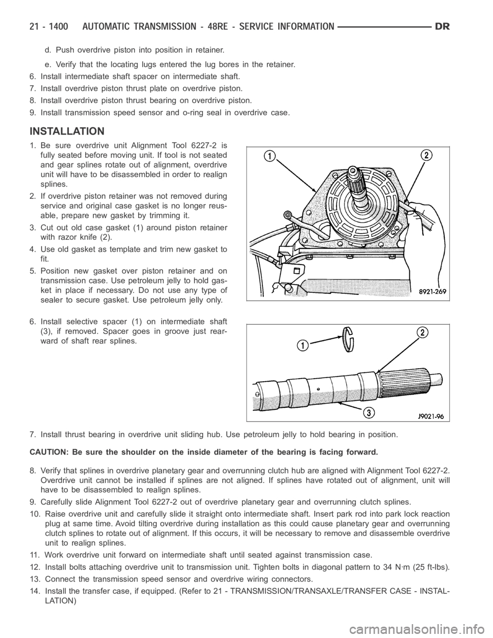
3. Cut out old case gasket (1) around piston retainer
with razor knife (2).
4. Use old gasket as template and trim new gasket to
fit.
5. Position new gasket over piston retainer and on
transmission case. Use petroleum jelly to hold gas-
ket in place if necessary. Do not use any type of
sealer to secure gasket. Use petroleum jelly only.
6. Install selective spacer (1) on intermediate shaft
(3), if removed. Spacer goes in groove just rear-
ward of shaft rear splines.
7. Install thrust bearing in overdrive unit sliding hub. Use petroleum jelly to hold bearing in position.
CAUTION: Be sure the shoulder on the inside diameter of the bearing is facingforward.
8. Verify that splines in overdrive planetary gear and overrunning clutchhub are aligned with Alignment Tool 6227-2.
Overdrive unit cannot be installed if splines are not aligned. If splines have rotated out of alignment, unit will
have to be disassembled to realign splines.
9. Carefully slide Alignment Tool 6227-2 out of overdrive planetary gear and overrunning clutch splines.
10. Raise overdrive unit and carefully slide it straight onto intermediate shaft. Insert park rod into park lock reaction
plug at same time. Avoid tilting overdrive during installation as this could cause planetary gear and overrunning
clutch splines to rotate out of alignment. If this occurs, it will be necessary to remove and disassemble overdrive
unit to realign splines.
11. Work overdrive unit forward on intermediate shaft until seated against transmission case.
12. Install bolts attaching overdrive unit to transmission unit. Tightenbolts in diagonal pattern to 34 Nꞏm (25 ft-lbs).
13. Connect the transmission speed sensor and overdrive wiring connectors.
14. Install the transfer case, if equipped. (Refer to 21 - TRANSMISSION/TRANSAXLE/TRANSFER CASE - INSTAL-
LATION)
Page 3931 of 5267
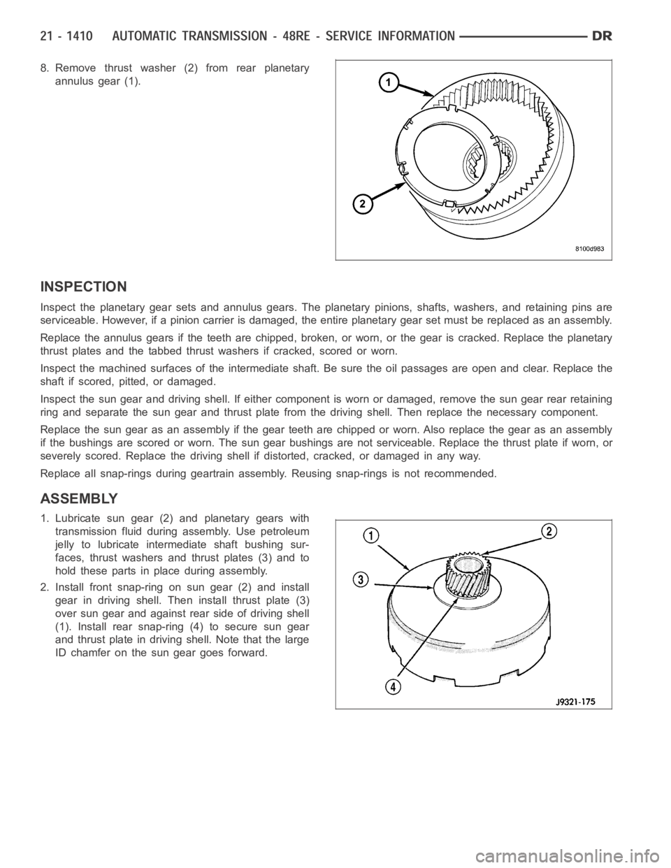
8. Remove thrust washer (2) from rear planetary
annulus gear (1).
INSPECTION
Inspect the planetary gear sets and annulus gears. The planetary pinions,shafts, washers, and retaining pins are
serviceable. However, if a pinion carrier is damaged, the entire planetarygearsetmustbereplacedasanassembly.
Replace the annulus gears if the teeth are chipped, broken, or worn, or the gear is cracked. Replace the planetary
thrust plates and the tabbed thrust washers if cracked, scored or worn.
Inspect the machined surfaces of the intermediate shaft. Be sure the oil passages are open and clear. Replace the
shaft if scored, pitted, or damaged.
Inspect the sun gear and driving shell. If either component is worn or damaged, remove the sun gear rear retaining
ring and separate the sun gear and thrust plate from the driving shell. Thenreplace the necessary component.
Replace the sun gear as an assembly if the gear teeth are chipped or worn. Also replace the gear as an assembly
if the bushings are scored or worn. The sun gear bushings are not serviceable. Replace the thrust plate if worn, or
severely scored. Replace the driving shell if distorted, cracked, or damaged in any way.
Replace all snap-rings during geartrain assembly. Reusing snap-rings isnot recommended.
ASSEMBLY
1. Lubricate sun gear (2) and planetary gears with
transmission fluid during assembly. Use petroleum
jelly to lubricate intermediate shaft bushing sur-
faces, thrust washers and thrust plates (3) and to
hold these parts in place during assembly.
2. Install front snap-ring on sun gear (2) and install
gear in driving shell. Then install thrust plate (3)
over sun gear and against rear side of driving shell
(1). Install rear snap-ring (4) to secure sun gear
and thrust plate in driving shell. Note that the large
ID chamfer on the sun gear goes forward.
Page 3952 of 5267
CONVERTER-TORQUE
DESCRIPTION
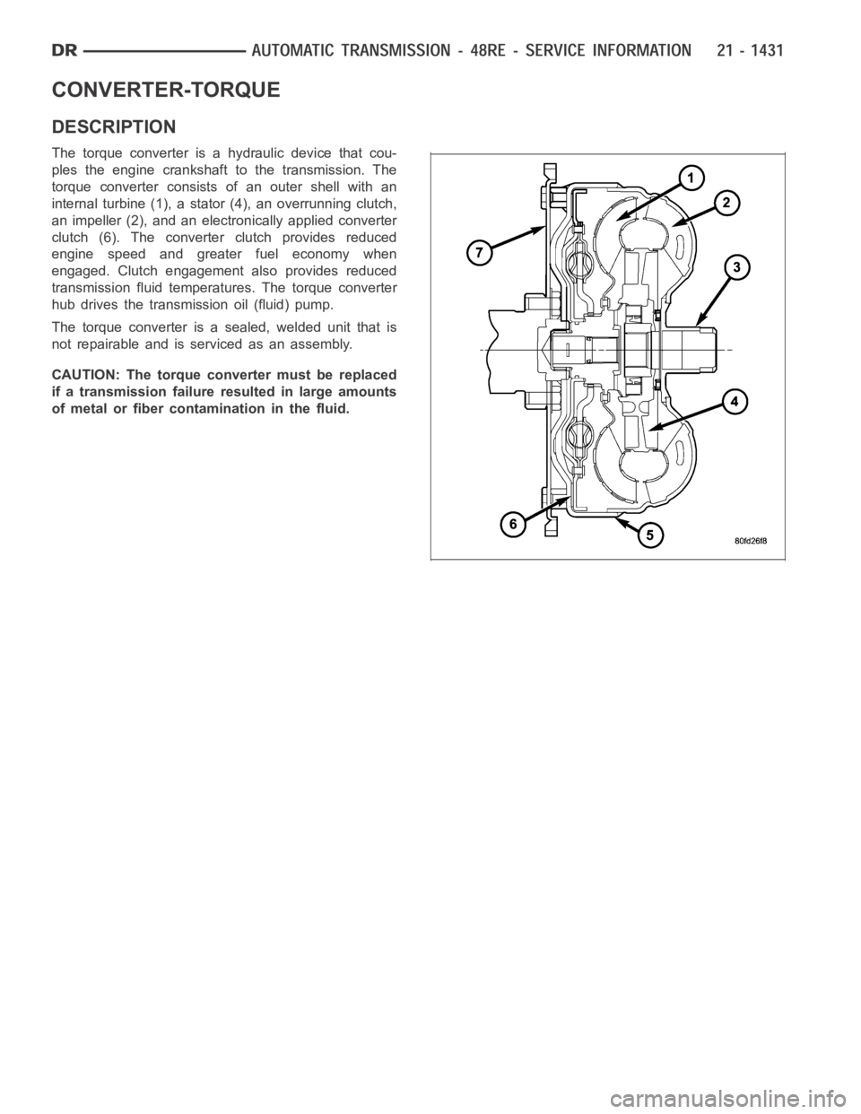
The torque converter is a hydraulic device that cou-
ples the engine crankshaft to the transmission. The
torque converter consists of an outer shell with an
internal turbine (1), a stator (4), an overrunning clutch,
an impeller (2), and an electronically applied converter
clutch (6). The converterclutch provides reduced
engine speed and greater fuel economy when
engaged. Clutch engagement also provides reduced
transmission fluid temperatures. The torque converter
hub drives the transmission oil (fluid) pump.
The torque converter is a sealed, welded unit that is
not repairable and is serviced as an assembly.
CAUTION: The torque converter must be replaced
if a transmission failure resulted in large amounts
of metal or fiber contamination in the fluid.
Page 3959 of 5267
VALVE-TORQUE CONVERTER DRAINBACK
DESCRIPTION
GAS ENGINES
The drainback valve is located in the transmission cooler outlet (pressure) line.
DIESEL ENGINE
The converter drainback check valve is located in the in the TOC pressure - supply line, between the engine
mounted TOC and the air to oil TOC.
OPERATION
GAS ENGINES
The valve prevents fluid from draining from the converter into the cooler and lines when the vehicle is shut down for
lengthy periods. Production valves have a hose nipple at one end, while theopposite end is threaded for a flare
fitting. All valves have an arrow (or similar mark) to indicate direction of flow through the valve.
DIESEL ENGINE
The valve prevents fluid from draining from the converter into the cooler and lines when the vehicle is shut down for
lengthy periods. Production valves have pipe thread on one end, while the opposite end is threaded for a flare
fitting, and are threaded into the oil cooler mounted on the side of the engine. All valves have an arrow (or similar
mark) to indicate direction of flow through the valve.
STANDARD PROCEDURE
GAS ENGINES
The converter drainback check valve is located in the cooler outlet (pressure) line near the radiator tank. The valve
prevents fluid drainback when the vehicle is parked for lengthy periods. The valve check ball is spring loaded and
has an opening pressure of approximately 2 psi.
The valve is serviced as an assembly; it is not repairable. Do not clean the valve if restricted, or contaminated by
sludge, or debris. If the valve fails, or if a transmission malfunction occurs that generates significant amounts of
sludge and/or clutch particles and metal shavings, the valve must be replaced.
If the valve is restricted, installed backwards, or in the wrong line, it will cause an transmission overheating condition
and possible transmission failure.
CAUTION: The drainback valve is a one-way flow device. It must be properly orientedintermsofflowdirec-
tion for the cooler to function properly. The valve must be installed in thepressure line. Otherwise flow will
be blocked and would cause an transmission overheating condition and eventual transmission failure.
DIESEL ENGINE
The converter drainback check valve is located in the in the TOC pressure - supply line, between the engine
mounted transmission oil cooler and the air to oil transmission oil cooler. The valve prevents fluid drainback when
the vehicle is parked for lengthy periods. The valve check ball is spring loaded and has an opening pressure of
approximately 2 psi.
The valve is serviced as an assembly; it is not repairable. Do not clean the valve if restricted, or contaminated by
sludge, or debris. If the valve fails, or if a transmission malfunction occurs that generates significant amounts of
sludge and/or clutch particles and metal shavings, the valve must be replaced.
If the valve is restricted, installed backwards, or in the wrong line, it will cause an transmission overheating condition
and possible transmission failure.
Page 3992 of 5267
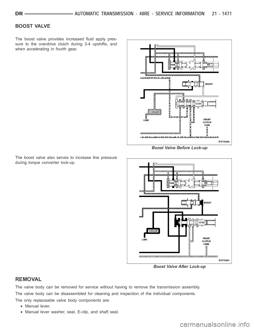
BOOST VALVE
The boost valve provides increased fluid apply pres-
sure to the overdrive clutch during 3-4 upshifts, and
when accelerating in fourth gear.
Theboostvalvealsoservestoincreaselinepressure
during torque converter lock-up.
REMOVAL
The valve body can be removed for service without having to remove the transmission assembly.
The valve body can be disassembled for cleaning and inspection of the individual components.
The only replaceable valve body components are:
Manual lever.
Manual lever washer, seal, E-clip, and shaft seal.
Boost Valve Before Lock-up
Boost Valve After Lock-up
Page 4006 of 5267

4. Remove timing valve cover.
5. Remove 3-4 timing valve and spring.
6. Remove 3-4 quick fill valve, spring and plug.
7. Remove 3-4 shift valve and spring.
8. Remove converter clutch valve, spring and plug.
9. Remove converter clutch timing valve, retainer and
valve spring.
CLEANING
Clean the valve housings, valves, plugs, springs, and separator plates with a standard parts cleaning solution only.
Do not use gasoline, kerosene, or any type of caustic solution.
Do not immerse any of the electrical components in cleaning solution. Clean the governor solenoid and sensor and
the dual solenoid and harness assembly by wiping them off with dry shop towels only.
Dry all except the electrical parts with compressed air. Make sure all passages are clean and free from obstructions.
Do not use rags or shop towels to dry or wipe off valve body components. Lint from these materials can
stick to valve body parts, interfere with valve operation, and clog filters and fluid passages.
Wipe the governor pressure sensor and solenoid valve with dry, lint free shop towels only. The O-rings on the sen-
sor and solenoid valve are the only serviceable components. Be sure the vent ports in the solenoid valve are open
and not blocked by dirt or debris. Replace the valve and/or sensor only whenDRB scan tool diagnosis indicates this
is necessary. Or, if either part has sustained physical damage (dented, deformed, broken, etc.).
CAUTION: Do not turn the small screw at the end of the solenoid valve for any reason. Turning the screw
in either direction will ruin solenoid calibration and result in solenoidfailure. In addition, the filter on the
solenoid valve is NOT serviceable. Do not try to remove the filter as this will damage the valve housing.
INSPECTION
Inspect the throttle and manual valve levers and shafts. Do not attempt to straighten a bent shaft or correct a loose
lever. Replace these components if worn, bent, loose or damaged in any way.
Inspect all of the valve body mating surfaces for scratches, nicks, burrs,or distortion. Use a straightedge to check
surface flatness. Minor scratches may be removed with crocus cloth using only very light pressure.
Minor distortion of a valve body mating surface may be corrected by smoothing the surface with a sheet of crocus
cloth. Position the crocus cloth on a surface plate, sheet of plate glass orequally flat surface. If distortion is severe
or any surfaces are heavily scored, the valve body will have to be replaced.
CAUTION: Many of the valves and plugs, such as the throttle valve, shuttle valve plug, 1-2 shift valve and
1-2 governor plug, are made of coated aluminum. Aluminum components are identified by the dark color of
thespecialcoatingappliedtothesurface(orbytestingwithamagnet).Donot sand aluminum valves or
plugs under any circumstances. This practice could damage the special coating causing the valves/plugs to
stick and bind.
Inspect the valves and plugs for scratches, burrs, nicks, or scores. Minorsurface scratches on steel valves and
plugs can be removed with crocus cloth butdo not round off the edges of the valve or plug lands.Maintaining
Page 4007 of 5267
sharpness of these edges is vitally important. The edges prevent foreign matter from lodging between the valves
and plugs and the bore.
Inspect all the valve and plug bores in the valve body. Use a penlight to viewthe bore interiors. Replace the valve
body if any bores are distorted or scored. Inspect all of the valve body springs. The springs must be free of dis-
tortion, warpage or broken coils.
Check the two separator plates for distortion or damage of any kind. Inspect the upper housing, lower housing, 3-4
accumulator housing, and transfer plate carefully. Be sure all fluid passages are clean and clear. Check condition of
the upper housing and transfer plate check balls as well. The check balls and ball seats must not be worn or dam-
aged.
Trial fit each valve and plug in its bore to check freedom of operation. Whenclean and dry, the valves and plugs
shoulddropfreelyintothebores.
Valve body bores do not change dimensionally with use. If the valve body functioned correctly when new, it will
continue to operate properly after cleaning and inspection. It should notbe necessary to replace a valve body
assembly unless it is damaged in handling.
The only serviceable valve body components are listed below. The remaining valve body components are serviced
only as part of a complete valve body assembly. Serviceable parts are:
dual solenoid and harness assembly
solenoid gasket
solenoid case connector O-rings and shoulder bolt
switch valve and spring
pressure adjusting screw and bracket assembly
throttle lever
manual lever and shaft seal
throttle lever shaft seal, washer, and E-clip
fluid filter and screws
detent ball and spring
valve body screws
governor pressure solenoid
governor pressure sensor and retaining clip
park lock rod and E-clip
ASSEMBLY
CAUTION: Do not force valves or plugs into place during reassembly. If the valve body bores, valves and
plugs are free of distortion or burrs, the valve body components should allslide into place easily. In addi-
tion, do not overtighten the transfer plate and valve body screws during reassembly. Overtightening can
distort the housings resulting in valve sticking, cross leakage and unsatisfactory operation. Tighten valve
body screws to recommended torque only.
Page 4025 of 5267
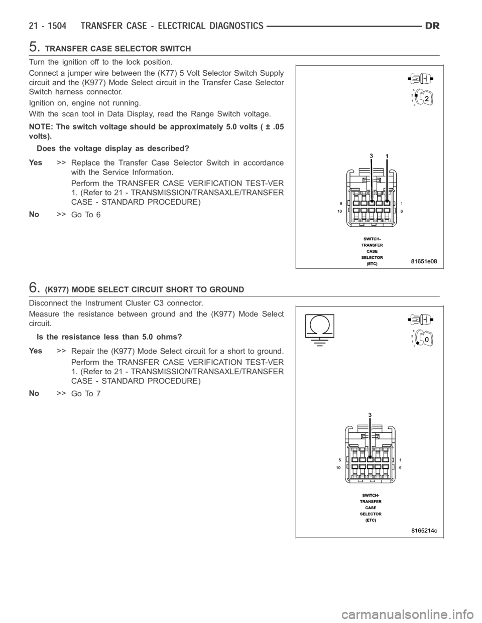
5.TRANSFER CASE SELECTOR SWITCH
Turn the ignition off to the lock position.
Connect a jumper wire between the (K77) 5 Volt Selector Switch Supply
circuit and the (K977) Mode Select circuit in the Transfer Case Selector
Switch harness connector.
Ignition on, engine not running.
With the scan tool in Data Display, read the Range Switch voltage.
NOTE: The switch voltage should be approximately 5.0 volts ( ± .05
volts).
Does the voltage display as described?
Ye s>>
Replace the Transfer Case Selector Switch in accordance
with the Service Information.
Perform the TRANSFER CASE VERIFICATION TEST-VER
1. (Refer to 21 - TRANSMISSION/TRANSAXLE/TRANSFER
CASE - STANDARD PROCEDURE)
No>>
Go To 6
6.(K977) MODE SELECT CIRCUIT SHORT TO GROUND
Disconnect the Instrument Cluster C3 connector.
Measure the resistance between ground and the (K977) Mode Select
circuit.
Is the resistance less than 5.0 ohms?
Ye s>>
Repair the (K977) Mode Select circuit for a short to ground.
Perform the TRANSFER CASE VERIFICATION TEST-VER
1. (Refer to 21 - TRANSMISSION/TRANSAXLE/TRANSFER
CASE - STANDARD PROCEDURE)
No>>
Go To 7