Page 2266 of 3171
OIL FILTER BRACKET
LU-9
C
D
E
F
G
H
I
J
K
L
MA
LU
OIL FILTER BRACKETPFP:15238
ComponentsEBS01F6C
lRefer toGI-10, "Components"for symbol marks except in the above.
Removal and InstallationEBS01E5A
REMOVAL
1. Remove mounting nuts (2) of fuel filter (1), and move it aside
with its hoses connected. Temporarily secure it with a rope to
avoid putting load on its hose.
2. Remove oil filter. Refer toLU-8, "
OIL FILTER".
3. Remove oil cooler. Refer toLU-11, "
OIL COOLER".
4. Remove oil filter bracket.
1. Oil filter 2. Oil filter bracket 3. Gasket
4. Drain hose 5. Connecting bolt 6. Washer
7. Oil cooler 8. O-ring 9. Cooper washer
10. Oil tube
A. Refer toLU-8
. B. To oil pan C. To vacuum pump
Vehicle front
PBIC3336E
: Vehicle front
PBIC3337E
Page 2269 of 3171

LU-12
OIL COOLER
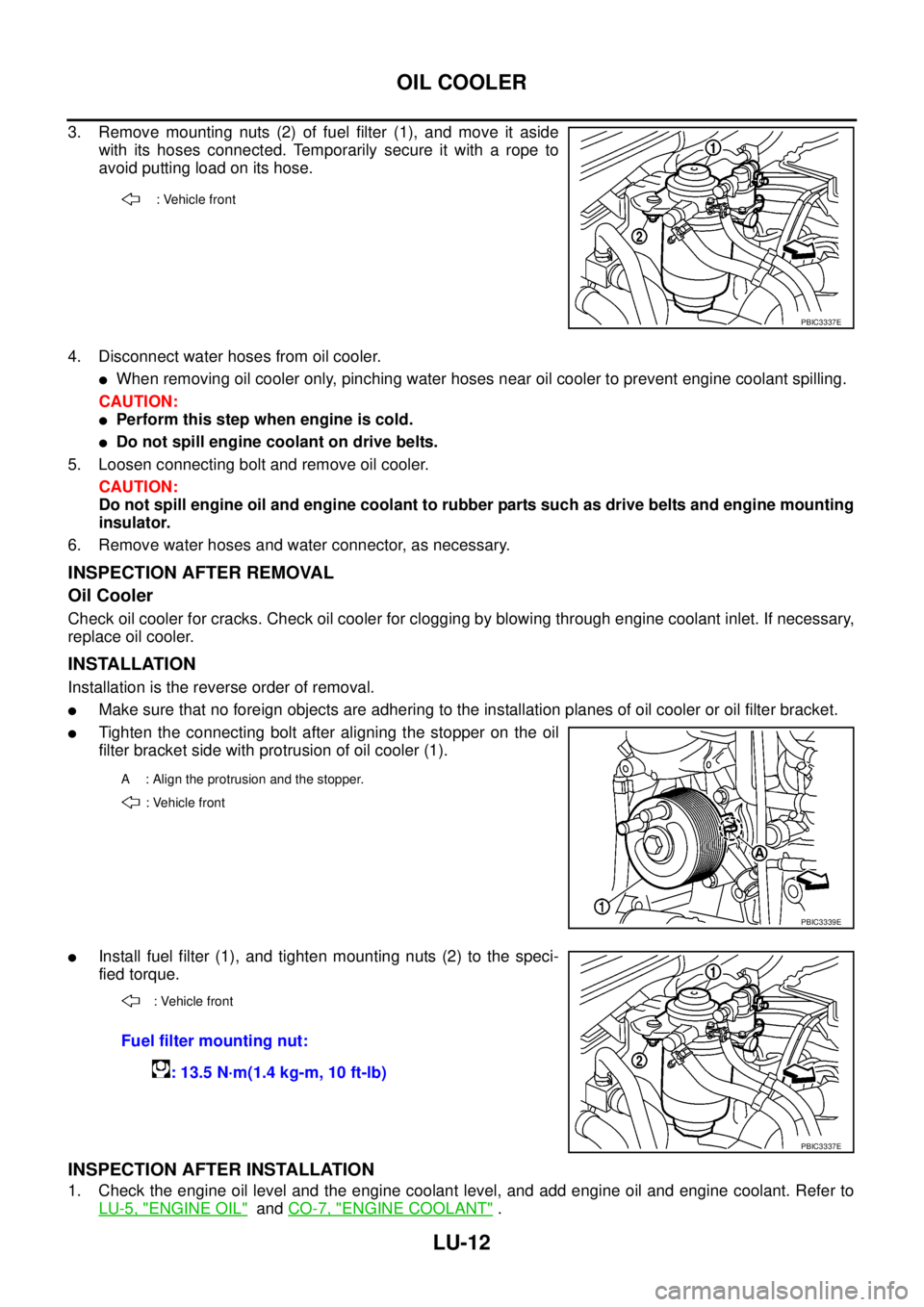
3. Remove mounting nuts (2) of fuel filter (1), and move it aside
with its hoses connected. Temporarily secure it with a rope to
avoid putting load on its hose.
4. Disconnect water hoses from oil cooler.
lWhen removing oil cooler only, pinching water hoses near oil cooler to prevent engine coolant spilling.
CAUTION:
lPerform this step when engine is cold.
lDo not spill engine coolant on drive belts.
5. Loosen connecting bolt and remove oil cooler.
CAUTION:
Do not spill engine oil and engine coolant to rubber parts such as drive belts and engine mounting
insulator.
6. Remove water hoses and water connector, as necessary.
INSPECTION AFTER REMOVAL
Oil Cooler
Check oil cooler for cracks. Check oil cooler for clogging by blowing through engine coolant inlet. If necessary,
replace oil cooler.
INSTALLATION
Installation is the reverse order of removal.
lMake sure that no foreign objects are adhering to the installation planes of oil cooler or oil filter bracket.
lTighten the connecting bolt after aligning the stopper on the oil
filter bracket side with protrusion of oil cooler (1).
lInstall fuel filter (1), and tighten mounting nuts (2) to the speci-
fied torque.
INSPECTION AFTER INSTALLATION
1. Check the engine oil level and the engine coolant level, and add engine oil and engine coolant. Refer to
LU-5, "
ENGINE OIL"andCO-7, "ENGINE COOLANT".
: Vehicle front
PBIC3337E
A : Align the protrusion and the stopper.
: Vehicle front
PBIC3339E
: Vehicle front
Fuel filter mounting nut:
: 13.5 N·m(1.4 kg-m, 10 ft-lb)
PBIC3337E
Page 2282 of 3171

GENERAL MAINTENANCE
MA-7
C
D
E
F
G
H
I
J
K
MA
B
MA
GENERAL MAINTENANCEPFP:00000
General MaintenanceELS001HT
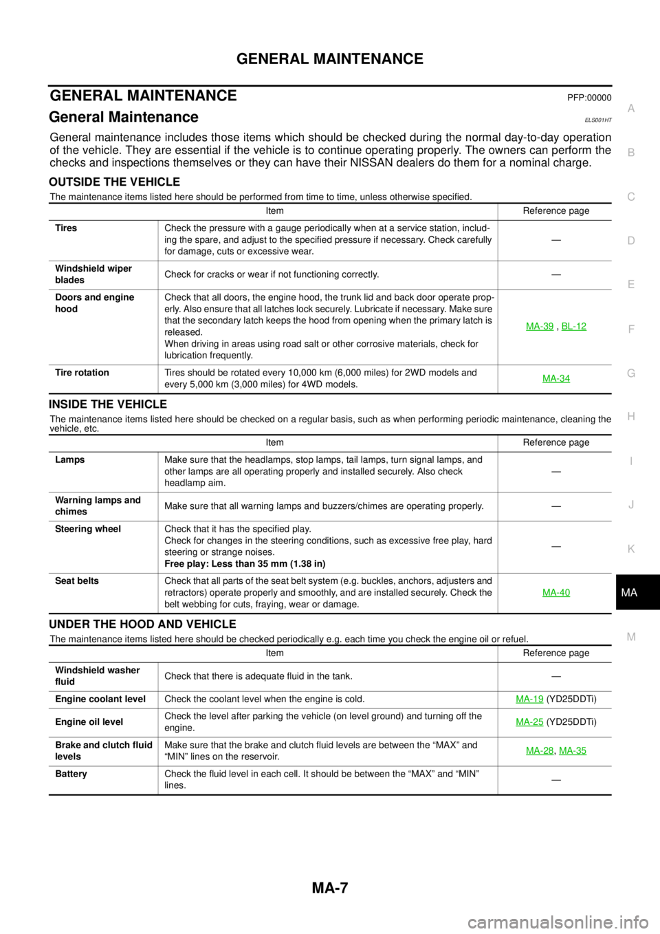
General maintenance includes those items which should be checked during the normal day-to-day operation
of the vehicle. They are essential if the vehicle is to continue operating properly. The owners can perform the
checks and inspections themselves or they can have their NISSAN dealers do them for a nominal charge.
OUTSIDE THE VEHICLE
The maintenance items listed here should be performed from time to time, unless otherwise specified.
INSIDE THE VEHICLE
The maintenance items listed here should be checked on a regular basis, such as when performing periodic maintenance, cleaning the
vehicle, etc.
UNDER THE HOOD AND VEHICLE
The maintenance items listed here should be checked periodically e.g. each time you check the engine oil or refuel.Item Reference page
TiresCheck the pressure with a gauge periodically when at a service station, includ-
ing the spare, and adjust to the specified pressure if necessary. Check carefully
for damage, cuts or excessive wear.—
Windshield wiper
bladesCheck for cracks or wear if not functioning correctly. —
Doors and engine
hoodCheck that all doors, the engine hood, the trunk lid and back door operate prop-
erly. Also ensure that all latches lock securely. Lubricate if necessary. Make sure
that the secondary latch keeps the hood from opening when the primary latch is
released.
When driving in areas using road salt or other corrosive materials, check for
lubrication frequently.MA-39
,BL-12
Tire rotationTires should be rotated every 10,000 km (6,000 miles) for 2WD models and
every 5,000 km (3,000 miles) for 4WD models.MA-34
Item Reference page
LampsMake sure that the headlamps, stop lamps, tail lamps, turn signal lamps, and
other lamps are all operating properly and installed securely. Also check
headlamp aim.—
Warning lamps and
chimesMake sure that all warning lamps and buzzers/chimes are operating properly. —
Steering wheelCheck that it has the specified play.
Check for changes in the steering conditions, such as excessive free play, hard
steering or strange noises.
Free play: Less than 35 mm (1.38 in)—
Seat beltsCheck that all parts of the seat belt system (e.g. buckles, anchors, adjusters and
retractors) operate properly and smoothly, and are installed securely. Check the
belt webbing for cuts, fraying, wear or damage.MA-40
Item Reference page
Windshield washer
fluidCheck that there is adequate fluid in the tank. —
Engine coolant levelCheck the coolant level when the engine is cold.MA-19
(YD25DDTi)
Engine oil levelCheck the level after parking the vehicle (on level ground) and turning off the
engine.MA-25
(YD25DDTi)
Brake and clutch fluid
levelsMake sure that the brake and clutch fluid levels are between the “MAX” and
“MIN” lines on the reservoir.MA-28
,MA-35
BatteryCheck the fluid level in each cell. It should be between the “MAX” and “MIN”
lines.—
Page 2335 of 3171

MT-18
TRANSMISSION ASSEMBLY
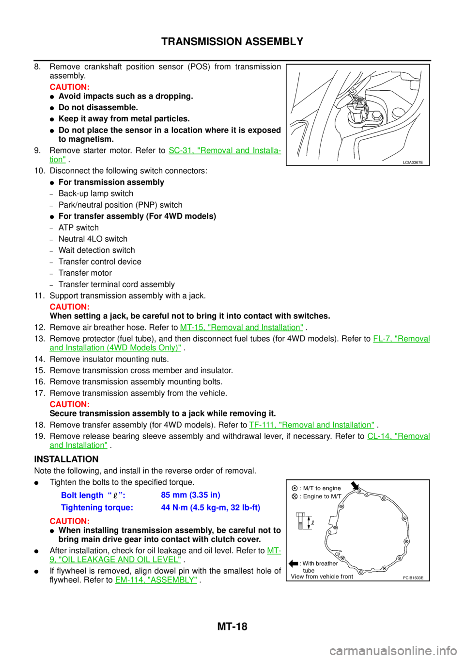
8. Remove crankshaft position sensor (POS) from transmission
assembly.
CAUTION:
lAvoid impacts such as a dropping.
lDo not disassemble.
lKeep it away from metal particles.
lDo not place the sensor in a location where it is exposed
to magnetism.
9. Remove starter motor. Refer toSC-31, "
Removal and Installa-
tion".
10. Disconnect the following switch connectors:
lFor transmission assembly
–Back-up lamp switch
–Park/neutral position (PNP) switch
lFor transfer assembly (For 4WD models)
–AT P s w i t c h
–Neutral 4LO switch
–Wait detection switch
–Transfer control device
–Transfer motor
–Transfer terminal cord assembly
11. Support transmission assembly with a jack.
CAUTION:
When setting a jack, be careful not to bring it into contact with switches.
12. Remove air breather hose. Refer toMT-15, "
Removal and Installation".
13. Remove protector (fuel tube), and then disconnect fuel tubes (for 4WD models). Refer toFL-7, "
Removal
and Installation (4WD Models Only)".
14. Remove insulator mounting nuts.
15. Remove transmission cross member and insulator.
16. Remove transmission assembly mounting bolts.
17. Remove transmission assembly from the vehicle.
CAUTION:
Secure transmission assembly to a jack while removing it.
18. Remove transfer assembly (for 4WD models). Refer toTF-111, "
Removal and Installation".
19. Remove release bearing sleeve assembly and withdrawal lever, if necessary. Refer toCL-14, "
Removal
and Installation".
INSTALLATION
Note the following, and install in the reverse order of removal.
lTighten the bolts to the specified torque.
CAUTION:
lWhen installing transmission assembly, be careful not to
bring main drive gear into contact with clutch cover.
lAfter installation, check for oil leakage and oil level. Refer toMT-
9, "OIL LEAKAGE AND OIL LEVEL".
lIf flywheel is removed, align dowel pin with the smallest hole of
flywheel. Refer toEM-114, "
ASSEMBLY".
LCIA0367E
Bolt length “ ”:85 mm (3.35 in)
Tightening torque: 44 N·m (4.5 kg-m, 32 lb-ft)
PCIB1603E
Page 2346 of 3171
TRANSMISSION ASSEMBLY
MT-29
D
E
F
G
H
I
J
K
L
MA
B
MT
21. Remove filler plug and gasket from transmission case.
Shift Control Components
1. Remove rear extension (or OD gear case) and transmission case. Refer toMT-25, "Case Components".
2. Install adapter setting plate to adapter plate, and then fixing in
adapter setting plate using a vise.
CAUTION:
Do not directly secure mating surface of adapter plate in a
vise.
3. Remove baffle plate mounting bolts, and then remove baffle
plate from adapter plate.
4. Remove check ball plugs, check ball springs and check balls
from adapter plate.
PCIB1229E
PCIB1408E
PCIB1325E
PCIB1231E
Page 2369 of 3171
MT-52
TRANSMISSION ASSEMBLY
a. Install main pilot bearing, pilot bearing spacer and 5th baulk ring
to main drive gear.
b. Install main drive gear assembly, mainshaft assembly and
counter gear assembly combined in one unit to adapter plate
using brass bar.
20. Install adapter setting plate to adapter plate, and then fixing in
adapter setting plate using a vise.
CAUTION:
Do not directly secure mating surface of adapter plate in a
vice.
21. Install snap ring to mainshaft bearing.
CAUTION:
Do not reuse snap ring.
22. Install counter rear bearing to adapter plate using the drift.
23. Install counter rear bearing spacer to counter gear.
CAUTION:
When installing counter rear bearing spacer, groove should
face to the rear side.
24. Install bearing retainer according to the following.
PCIB0151E
PCIB1421E
SCIA1691E
PCIB1386E
Page 2394 of 3171

PRECAUTIONS
MTC-7
C
D
E
F
G
H
I
K
L
MA
B
MTC
INSTALLATION
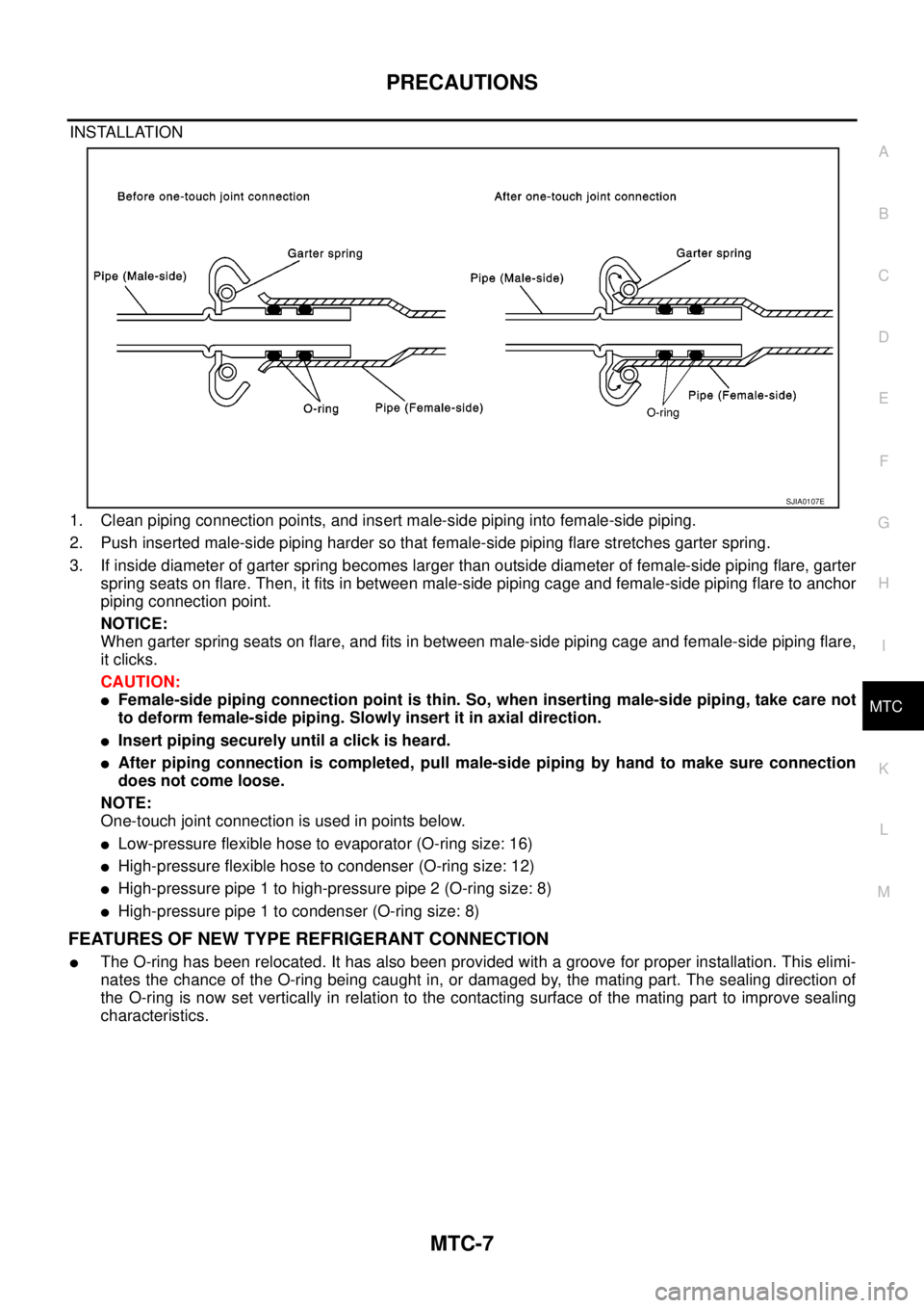
1. Clean piping connection points, and insert male-side piping into female-side piping.
2. Push inserted male-side piping harder so that female-side piping flare stretches garter spring.
3. If inside diameter of garter spring becomes larger than outside diameter of female-side piping flare, garter
spring seats on flare. Then, it fits in between male-side piping cage and female-side piping flare to anchor
piping connection point.
NOTICE:
When garter spring seats on flare, and fits in between male-side piping cage and female-side piping flare,
it clicks.
CAUTION:
lFemale-side piping connection point is thin. So, when inserting male-side piping, take care not
to deform female-side piping. Slowly insert it in axial direction.
lInsert piping securely until a click is heard.
lAfter piping connection is completed, pull male-side piping by hand to make sure connection
does not come loose.
NOTE:
One-touch joint connection is used in points below.
lLow-pressure flexible hose to evaporator (O-ring size: 16)
lHigh-pressure flexible hose to condenser (O-ring size: 12)
lHigh-pressure pipe 1 to high-pressure pipe 2 (O-ring size: 8)
lHigh-pressure pipe 1 to condenser (O-ring size: 8)
FEATURES OF NEW TYPE REFRIGERANT CONNECTION
lThe O-ring has been relocated. It has also been provided with a groove for proper installation. This elimi-
nates the chance of the O-ring being caught in, or damaged by, the mating part. The sealing direction of
the O-ring is now set vertically in relation to the contacting surface of the mating part to improve sealing
characteristics.
SJIA0107E
Page 2485 of 3171
MTC-98
CONTROL UNIT
CONTROL UNIT
PFP:27500
Removal and InstallationEJS005GS
REMOVAL
1. Remove the five control knobs from the front air control unit.
2. Remove the cluster lid C. Refer toIP-11, "
CLUSTER LID C".
3. Remove the four screws securing the front air control unit to the
cluster lid C.
4. Remove the front air control unit.
INSTALLATION
Installation is in the reverse order of removal.
LJIA0130E