2005 NISSAN NAVARA ECU
[x] Cancel search: ECUPage 1625 of 3171

PRECAUTIONS
GI-3
C
D
E
F
G
H
I
J
K
L
MB
GI
PRECAUTIONSPFP:00001
DescriptionEAS001GG
Observe the following precautions to ensure safe and proper servicing. These precautions are not
described in each individual section.
Precautions for Supplemental Restraint System (SRS) “AIR BAG” and “SEAT
BELT PRE-TENSIONER”
EAS001GH
The Supplemental Restraint System such as “AIR BAG” and “SEAT BELT PRE-TENSIONER”, used along
with a front seat belt, helps to reduce the risk or severity of injury to the driver and front passenger for certain
types of collision. Information necessary to service the system safely is included in the SRS and SB section of
this Service Manual.
WARNING:
lTo avoid rendering the SRS inoperative, which could increase the risk of personal injury or death
in the event of a collision which would result in air bag inflation, all maintenance must be per-
formed by an authorized NISSAN/INFINITI dealer.
lImproper maintenance, including incorrect removal and installation of the SRS, can lead to per-
sonal injury caused by unintentional activation of the system. For removal of Spiral Cable and Air
Bag Module, see the SRS section.
lDo not use electrical test equipment on any circuit related to the SRS unless instructed to in this
Service Manual. SRS wiring harnesses can be identified by yellow and/or orange harnesses or
harness connectors.
Precautions for NATS (NISSAN ANTI-THEFT SYSTEM)EAS001GI
NATS will immobilize the engine if someone tries to start it without the registered key of NATS.
Both of the originally supplied ignition key IDs have been NATS registered.
The security indicator is located on the instrument panel. The indicator blinks when the immobilizer system is
functioning.
Therefore, NATS warns outsiders that the vehicle is equipped with the anti-theft system.
lWhen NATS detects trouble, the security indicator lamp lights up while ignition switch is in "ON" position.
This lighting up indicates that the anti-theft is not functioning, so prompt service is required.
lWhen servicing NATS (trouble diagnoses, system initialization and additional registration of other NATS
ignition key IDs), CONSULT-II hardware and CONSULT-II NATS software is necessary.
Regarding the procedures of NATS initialization and NATS ignition key ID registration, refer to CONSULT-
II operation manual, NATS.
Therefore, CONSULT-II NATS software (program card and operation manual) must be kept strictly con-
fidential to maintain the integrity of the anti-theft function.
lWhen servicing NATS (trouble diagnoses, system initialization and additional registration of other NATS
ignition key IDs), it may be necessary to re-register original key identification. Therefore, be sure to
receive all keys from vehicle owner. A maximum of four or five key IDs can be registered into NATS.
lWhen failing to start the engine first time using the key of NATS, start as follows.
1. Leave the ignition key in "ON" position for approximately 5 seconds.
2. Turn ignition key to "OFF" or "LOCK" position and wait approximately 5 seconds.
3. Repeat step 1 and 2 again.
4. Restart the engine while keeping the key separate from any others on key-chain.
Precautions Necessary for Steering Wheel Rotation After Battery DisconnectEAS001HY
NOTE:
lThis Procedure is applied only to models with Intelligent Key system and NATS (NISSAN ANTI-THEFT
SYSTEM).
lRemove and install all control units after disconnecting both battery cables with the ignition knob in the
²LOCK²position.
lAlways use CONSULT-II to perform self-diagnosis as a part of each function inspection after finishing
work. If DTC is detected, perform trouble diagnosis according to self-diagnostic results.
For models equipped with the Intelligent Key system and NATS, an electrically controlled steering lock mech-
anism is adopted on the key cylinder.
Page 1629 of 3171
PRECAUTIONS
GI-7
C
D
E
F
G
H
I
J
K
L
MB
GI
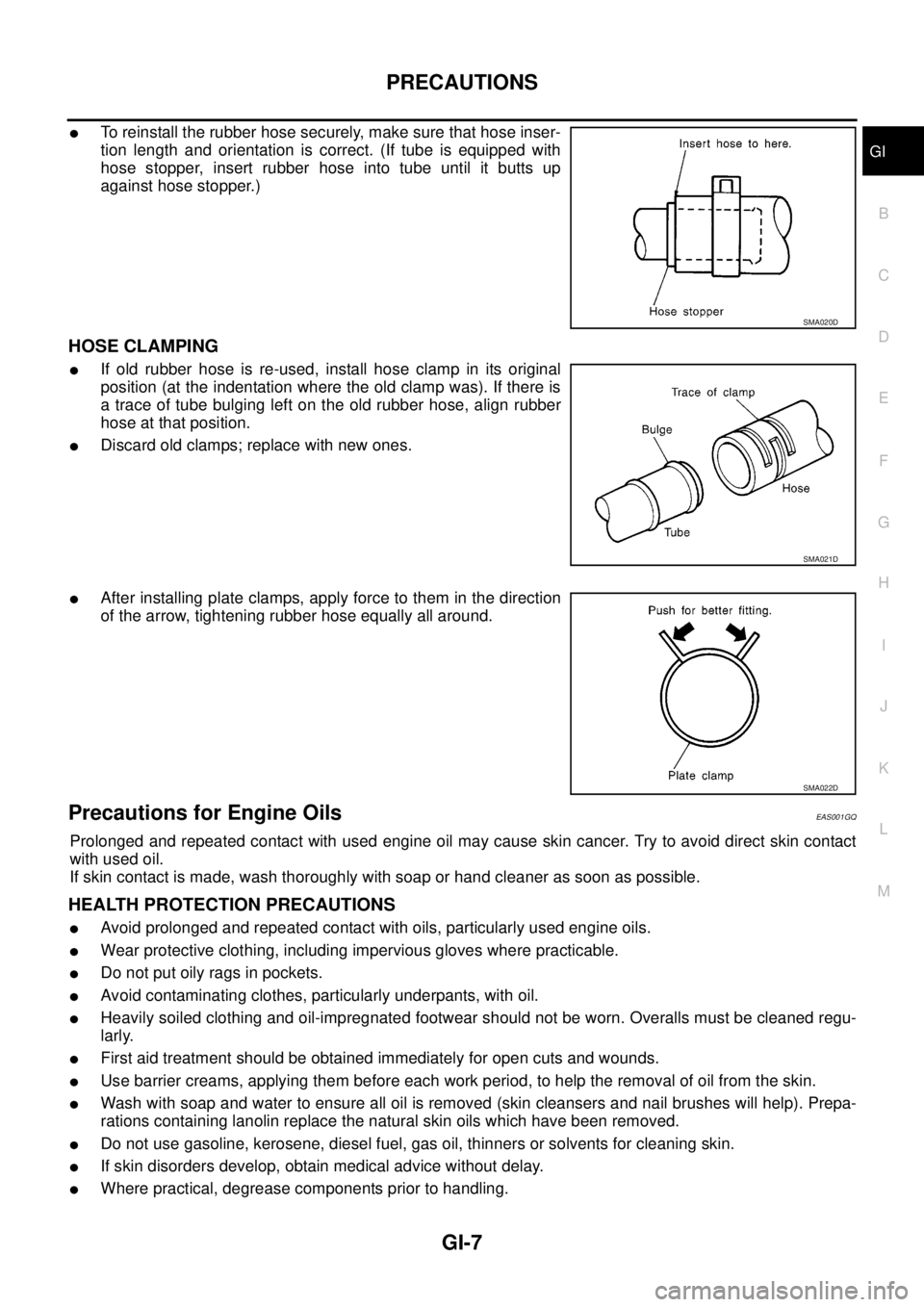
lTo reinstall the rubber hose securely, make sure that hose inser-
tion length and orientation is correct. (If tube is equipped with
hose stopper, insert rubber hose into tube until it butts up
against hose stopper.)
HOSE CLAMPING
lIf old rubber hose is re-used, install hose clamp in its original
position (at the indentation where the old clamp was). If there is
a trace of tube bulging left on the old rubber hose, align rubber
hose at that position.
lDiscard old clamps; replace with new ones.
lAfter installing plate clamps, apply force to them in the direction
of the arrow, tightening rubber hose equally all around.
Precautions for Engine OilsEAS001GQ
Prolonged and repeated contact with used engine oil may cause skin cancer. Try to avoid direct skin contact
with used oil.
If skin contact is made, wash thoroughly with soap or hand cleaner as soon as possible.
HEALTH PROTECTION PRECAUTIONS
lAvoid prolonged and repeated contact with oils, particularly used engine oils.
lWear protective clothing, including impervious gloves where practicable.
lDo not put oily rags in pockets.
lAvoid contaminating clothes, particularly underpants, with oil.
lHeavily soiled clothing and oil-impregnated footwear should not be worn. Overalls must be cleaned regu-
larly.
lFirst aid treatment should be obtained immediately for open cuts and wounds.
lUse barrier creams, applying them before each work period, to help the removal of oil from the skin.
lWash with soap and water to ensure all oil is removed (skin cleansers and nail brushes will help). Prepa-
rations containing lanolin replace the natural skin oils which have been removed.
lDo not use gasoline, kerosene, diesel fuel, gas oil, thinners or solvents for cleaning skin.
lIf skin disorders develop, obtain medical advice without delay.
lWhere practical, degrease components prior to handling.
SMA020D
SMA021D
SMA022D
Page 1651 of 3171
SERVICE INFORMATION FOR ELECTRICAL INCIDENT
GI-29
C
D
E
F
G
H
I
J
K
L
MB
GI
no voltage; short is further down the circuit than SW1.
lWith SW1 closed, relay and solenoid disconnected and the DMM leads across both fuse terminals, check
for voltage.
voltage; short is between SW1 and the relay (point B).
no voltage; short is further down the circuit than the relay.
lWith SW1 closed, relay contacts jumped with fused jumper wire check for voltage.
voltage; short is down the circuit of the relay or between the relay and the disconnected solenoid (point C).
no voltage; retrace steps and check power to fuse block.
Ground Inspection
Ground connections are very important to the proper operation of electrical and electronic circuits. Ground
connections are often exposed to moisture, dirt and other corrosive elements. The corrosion (rust) can
become an unwanted resistance. This unwanted resistance can change the way a circuit works.
Electronically controlled circuits are very sensitive to proper grounding. A loose or corroded ground can drasti-
cally affect an electronically controlled circuit. A poor or corroded ground can easily affect the circuit. Even
when the ground connection looks clean, there can be a thin film of rust on the surface.
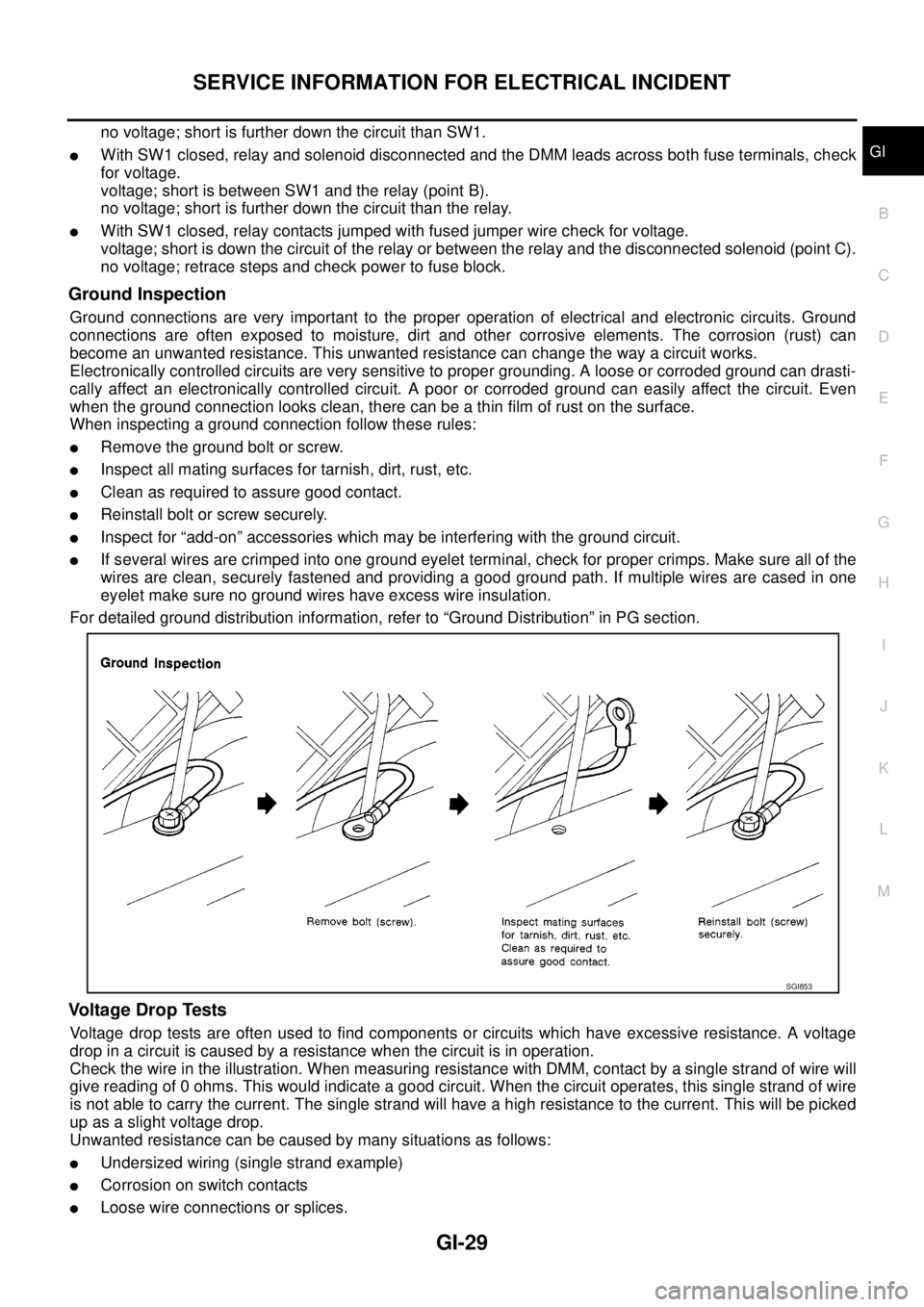
When inspecting a ground connection follow these rules:
lRemove the ground bolt or screw.
lInspect all mating surfaces for tarnish, dirt, rust, etc.
lClean as required to assure good contact.
lReinstall bolt or screw securely.
lInspect for “add-on” accessories which may be interfering with the ground circuit.
lIf several wires are crimped into one ground eyelet terminal, check for proper crimps. Make sure all of the
wires are clean, securely fastened and providing a good ground path. If multiple wires are cased in one
eyelet make sure no ground wires have excess wire insulation.
For detailed ground distribution information, refer to “Ground Distribution” in PG section.
Voltage Drop Tests
Voltage drop tests are often used to find components or circuits which have excessive resistance. A voltage
drop in a circuit is caused by a resistance when the circuit is in operation.
Check the wire in the illustration. When measuring resistance with DMM, contact by a single strand of wire will
give reading of 0 ohms. This would indicate a good circuit. When the circuit operates, this single strand of wire
is not able to carry the current. The single strand will have a high resistance to the current. This will be picked
up as a slight voltage drop.
Unwanted resistance can be caused by many situations as follows:
lUndersized wiring (single strand example)
lCorrosion on switch contacts
lLoose wire connections or splices.
SGI853
Page 1666 of 3171
GI-44
CONTROL UNIT CONFIGURATION PROCEDURE
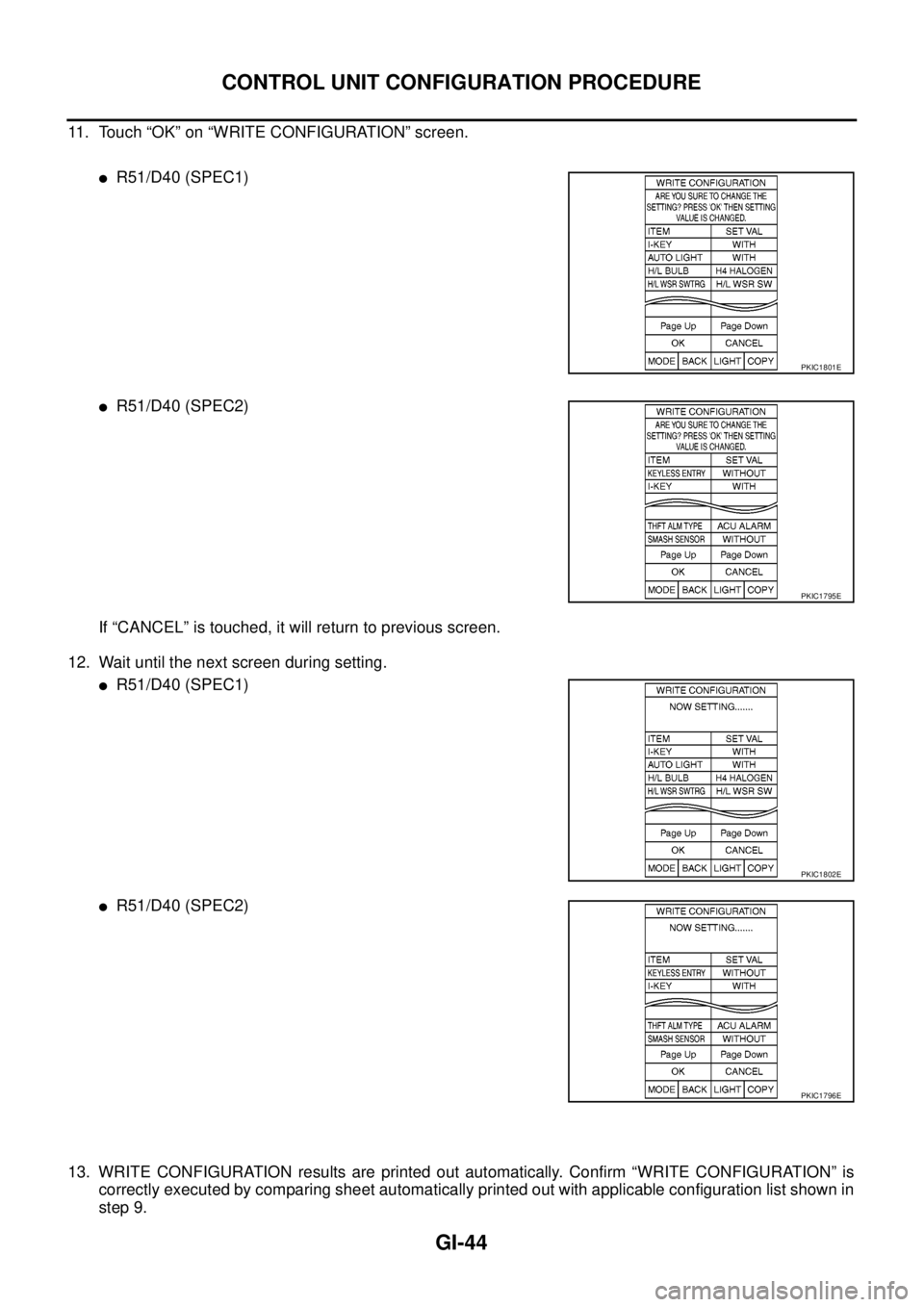
11. Touch “OK” on “WRITE CONFIGURATION” screen.
lR51/D40 (SPEC1)
lR51/D40 (SPEC2)
If “CANCEL” is touched, it will return to previous screen.
12. Wait until the next screen during setting.
lR51/D40 (SPEC1)
lR51/D40 (SPEC2)
13. WRITE CONFIGURATION results are printed out automatically. Confirm “WRITE CONFIGURATION” is
correctly executed by comparing sheet automatically printed out with applicable configuration list shown in
step 9.
PKIC1801E
PKIC1795E
PKIC1802E
PKIC1796E
Page 1669 of 3171

CONSULT-II CHECKING SYSTEM
GI-47
C
D
E
F
G
H
I
J
K
L
MB
GI
CONSULT-II CHECKING SYSTEMPFP:00000
DescriptionEAS001H2
lCONSULT-II is a hand-held type tester. When it is connected with a diagnostic connector equipped on the
vehicle side, it will communicate with the control unit equipped in the vehicle and then enable various
kinds of diagnostic tests.
lRefer to “CONSULT-II Software Operation Manual” for more information.
Function and System ApplicationEAS001H3
x: Applicable
*: Nissan Anti-Theft SystemDiagnostic test
modeFunction
ENGINE
A/T
AIR BAG
ABS
ALL MODE AWD/4WD
BCM
IPDM E/R
MULTI AV
METER
NATS *
Work supportThis mode enables a technician to adjust some devices
faster and more accurately by following the indications
on CONSULT-II.x---´´--- -
Self-diagnostic
resultsSelf-diagnostic results can be read and erased quickly. x x x x x´´´´x
Trouble diagnostic
recordCurrent self-diagnostic results and all trouble diagnostic
records previously stored can be read.--x------ -
Data monitor Input/Output data in the ECU can be read. x x - x x´´´´-
CAN diagnosis
support monitorThe communication condition of CAN communication
line can be indicated.xx - xx´´´´-
Active testDiagnostic Test Mode in which CONSULT-II drives some
actuators apart from the ECU and also shifts some
parameters in a specified range.x- -x-´´-- -
DTC confirmationThe results of SRT (System Readiness Test) and the
self-diagnosis status/result can be confirmed.x----- - -- -
DTC work supportThe operating condition to confirm Diagnosis Trouble
Codes can be selected.-x------- -
ECM (ECU/TCM)
part numberECM (ECU/TCM) part number can be read. x x - x x´-´--
ECU discrimi-
nated No.Classification number of a replacement ECU can be read
to prevent an incorrect ECU from being installed.--x------ -
Function testThis mode can show results of self-diagnosis of ECU
with either “OK” or “NG”. For engines, more practical
tests regarding sensor/switches and/or actuators are
available.xxxx-- - - - -
Control unit initial-
izationAll registered ignition key IDs in NATS components can
be initialized and new IDs can be registered.------ - -- x
AV C O M M m o n i t o rIndicates the communication condition of AV communi-
cation.- ----- -´--
ConfigurationThe vehicle configuration can be read and written on
brand-new ECU- ----´--- -
Page 1675 of 3171
TOW TRUCK TOWING
GI-53
C
D
E
F
G
H
I
J
K
L
MB
GI
TOW TRUCK TOWINGPFP:00000
To w Tr u c k To w i n gEAS001DI
WARNING:
lNever get under the vehicle while it is supported only by the jack. Always use safety stands to
support the frame when you have to get under the vehicle.
lPlace wheel chocks at both front and back of the wheels on the ground.
CAUTION:
lAll applicable local laws regarding the towing operation must be obeyed.
lIt is necessary to use proper towing equipment to avoid possible damage during towing opera-
tion. Towing is in accordance with Towing Procedure Manual at dealer.
lAlways attach safety chains before towing.
lWhen towing, make sure that the transmission, steering system and powertrain are in good order.
If any unit is damaged, dollies must be used.
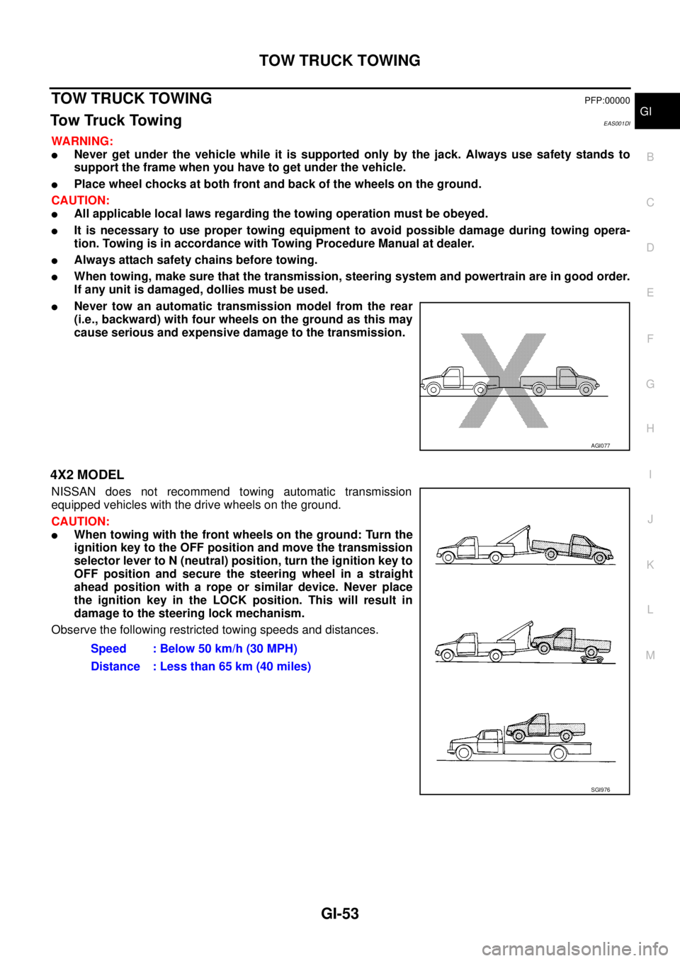
lNever tow an automatic transmission model from the rear
(i.e., backward) with four wheels on the ground as this may
cause serious and expensive damage to the transmission.
4X2 MODEL
NISSAN does not recommend towing automatic transmission
equipped vehicles with the drive wheels on the ground.
CAUTION:
lWhen towing with the front wheels on the ground: Turn the
ignition key to the OFF position and move the transmission
selector lever to N (neutral) position, turn the ignition key to
OFF position and secure the steering wheel in a straight
ahead position with a rope or similar device. Never place
the ignition key in the LOCK position. This will result in
damage to the steering lock mechanism.
Observe the following restricted towing speeds and distances.
AGI077
Speed : Below 50 km/h (30 MPH)
Distance : Less than 65 km (40 miles)
SGI976
Page 1676 of 3171
GI-54
TOW TRUCK TOWING
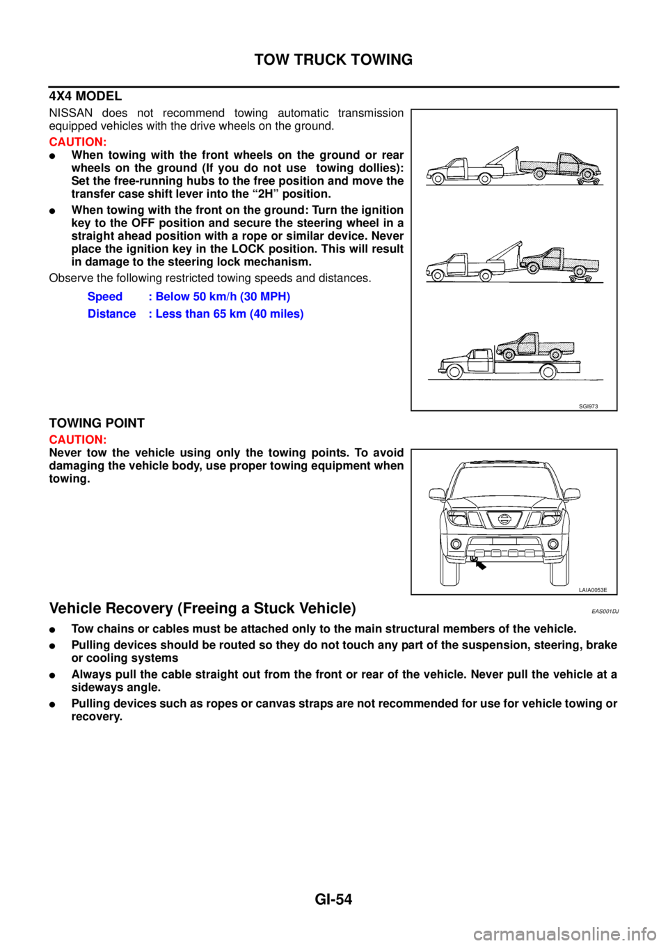
4X4 MODEL
NISSAN does not recommend towing automatic transmission
equipped vehicles with the drive wheels on the ground.
CAUTION:
lWhen towing with the front wheels on the ground or rear
wheels on the ground (If you do not use towing dollies):
Set the free-running hubs to the free position and move the
transfer case shift lever into the “2H” position.
lWhen towing with the front on the ground: Turn the ignition
key to the OFF position and secure the steering wheel in a
straight ahead position with a rope or similar device. Never
place the ignition key in the LOCK position. This will result
in damage to the steering lock mechanism.
Observe the following restricted towing speeds and distances.
TOWING POINT
CAUTION:
Never tow the vehicle using only the towing points. To avoid
damaging the vehicle body, use proper towing equipment when
towing.
Vehicle Recovery (Freeing a Stuck Vehicle)EAS001DJ
lTow chains or cables must be attached only to the main structural members of the vehicle.
lPulling devices should be routed so they do not touch any part of the suspension, steering, brake
or cooling systems
lAlways pull the cable straight out from the front or rear of the vehicle. Never pull the vehicle at a
sideways angle.
lPulling devices such as ropes or canvas straps are not recommended for use for vehicle towing or
recovery.Speed : Below 50 km/h (30 MPH)
Distance : Less than 65 km (40 miles)
SGI973
LAIA0053E
Page 1692 of 3171
GW-6
SQUEAK AND RATTLE TROUBLE DIAGNOSES
DUPLICATE THE NOISE AND TEST DRIVE
If possible, drive the vehicle with the customer until the noise is duplicated. Note any additional information on
the Diagnostic Worksheet regarding the conditions or location of the noise. This information can be used to
duplicate the same conditions when you confirm the repair.
If the noise can be duplicated easily during the test drive, to help identify the source of the noise, try to dupli-
cate the noise with the vehicle stopped by doing one or all of the following:
1) Close a door.
2) Tap or push/pull around the area where the noise appears to be coming from.
3) Rev the engine.
4) Use a floor jack to recreate vehicle “twist”.
5) At idle, apply engine load (electrical load, half-clutch on M/T model, drive position on A/T model).
6) Raise the vehicle on a hoist and hit a tire with a rubber hammer.
lDrive the vehicle and attempt to duplicate the conditions the customer states exist when the noise occurs.
lIf it is difficult to duplicate the noise, drive the vehicle slowly on an undulating or rough road to stress the
vehicle body.
CHECK RELATED SERVICE BULLETINS
After verifying the customer concern or symptom, check ASIST for Technical Service Bulletins (TSBs) related
to that concern or symptom.
If a TSB relates to the symptom, follow the procedure to repair the noise.
LOCATE THE NOISE AND IDENTIFY THE ROOT CAUSE
1. Narrow down the noise to a general area. To help pinpoint the source of the noise, use a listening tool
(Engine Ear or mechanics stethoscope).
2. Narrowdownthenoisetoamorespecificareaandidentifythecauseofthenoiseby:
lremoving the components in the area that you suspect the noise is coming from.
Do not use too much force when removing clips and fasteners, otherwise clips and fastener can be broken
or lost during the repair, resulting in the creation of new noise.
ltapping or pushing/pulling the component that you suspect is causing the noise.
Do not tap or push/pull the component with excessive force, otherwise the noise will be eliminated only
temporarily.
lfeeling for a vibration with your hand by touching the component(s) that you suspect is (are) causing the
noise.
lplacing a piece of paper between components that you suspect are causing the noise.
llooking for loose components and contact marks.
Refer toGW-7, "
Generic Squeak and Rattle Troubleshooting".
REPAIR THE CAUSE
lIf the cause is a loose component, tighten the component securely.
lIf the cause is insufficient clearance between components:
–separate components by repositioning or loosening and retightening the component, if possible.
–insulate components with a suitable insulator such as urethane pads, foam blocks, felt cloth tape or ure-
thane tape are available through your authorized Nissan Parts Department.
CAUTION:
Do not use excessive force as many components are constructed of plastic and may be damaged.
NOTE:
Always check with the Parts Department for the latest parts information.
Each item can be ordered separately as needed.
URETHANE PADS [1.5 mm (0.059 in) thick]
Insulates connectors, harness, etc.
76268-9E005: 100´135 mm (3.94´5.31 in)/76884-71L01: 60´85 mm (2.36´3.35 in)/76884-71L02: 15´
25 mm (0.59´0.98 in)
INSULATOR (Foam blocks)
Insulates components from contact. Can be used to fill space behind a panel.
73982-9E000: 45 mm (1.77 in) thick, 50´50 mm (1.97´1.97 in)/73982-50Y00: 10 mm (0.39 in) think, 50
´50 mm (1.97´1.97 in)
INSULATOR (Light foam block)
80845-71L00: 30 mm (1.18 in) thick, 30´50 mm (1.18´1.97 in)