2005 NISSAN NAVARA ECU
[x] Cancel search: ECUPage 1463 of 3171
![NISSAN NAVARA 2005 Repair Workshop Manual PRIMARY TIMING CHAIN
EM-81
C
D
E
F
G
H
I
J
K
L
MA
EM
c. Using the pulley puller [SST], remove crankshaft pulley.
lUse two M6 bolts with approx. 60 mm (2.36 in) shank length
for securing crankshaft pul NISSAN NAVARA 2005 Repair Workshop Manual PRIMARY TIMING CHAIN
EM-81
C
D
E
F
G
H
I
J
K
L
MA
EM
c. Using the pulley puller [SST], remove crankshaft pulley.
lUse two M6 bolts with approx. 60 mm (2.36 in) shank length
for securing crankshaft pul](/manual-img/5/57362/w960_57362-1462.png)
PRIMARY TIMING CHAIN
EM-81
C
D
E
F
G
H
I
J
K
L
MA
EM
c. Using the pulley puller [SST], remove crankshaft pulley.
lUse two M6 bolts with approx. 60 mm (2.36 in) shank length
for securing crankshaft pulley.
9. Remove oil pump housing.
lLoosen bolts in reverse order of that shown in the figure and
remove them.
lU s e t h e s e a l c u t t e r [ S S T: K V 1 0 1111 0 0 ] e t c . f o r r e m o v a l .
10. Remove crankshaft gear.
lRemove crankshaft gear (1) with the following procedure
(4WD models).
a. Make sure that No.1 piston is TDC on its compression stroke.
b. Turn the idler sub gear (3) counterclockwise with snap ring plier
(B) or suitable tool for aligning idler sub gear (3) and idler main
gear (2).
lIf idler gear rotates, hold the flat faces on balancer drive shaft
front end (4).
c. Install internal mechanism securing bolt and plate (Service part:
13012 EB30A and 13013 EB30A) (A) and tighten to the speci-
fied torque.
CAUTION:
lDo not loosen idler gear mounting bolt (5).
lOnly use the genuine internal mechanism securing bolt
and plate (A), or the idler gear (2) and (3) will be damaged.
lDo not remove internal mechanism securing bolt and
plate (A) from idler gear (2) and (3) until crankshaft gear
(1) and all of the parts in connection have been installed.
lIf internal mechanism securing bolt and plate (A) is not
installed, internal mechanism of idler gear (2) and (3) will
disengage after crankshaft gear (1) is removed. This will prohibit the balancer unit from being
reusable.
d. Apply mating marks (C) to crankshaft gear (1) and idler sub gear (3).
e. Remove crankshaft gear (1).
11. Remove front oil seal from oil pump housing.
lPunch out the seal off from the back surface of the oil pump housing using a flat-bladed screwdriver.
CAUTION:
Be careful not to damage oil pump housing.
JEM132G
PBIC3470E
: 4.0 N·m (0.41 kg-m, 35 in-lb)
PBIC3471E
Page 1471 of 3171
PRIMARY TIMING CHAIN
EM-89
C
D
E
F
G
H
I
J
K
L
MA
EM
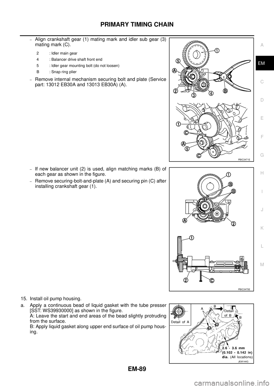
–Align crankshaft gear (1) mating mark and idler sub gear (3)
mating mark (C).
–Remove internal mechanism securing bolt and plate (Service
part: 13012 EB30A and 13013 EB30A) (A).
–If new balancer unit (2) is used, align matching marks (B) of
each gear as shown in the figure.
–Remove securing-bolt-and-plate (A) and securing pin (C) after
installing crankshaft gear (1).
15. Install oil pump housing.
a. Apply a continuous bead of liquid gasket with the tube presser
[SST: WS39930000] as shown in the figure.
A: Leave the start and end areas of the bead slightly protruding
from the surface.
B: Apply liquid gasket along upper end surface of oil pump hous-
ing.
2 : Idler main gear
4 : Balancer drive shaft front end
5 : Idler gear mounting bolt (do not loosen)
B : Snap ring plier
PBIC3471E
PBIC3475E
JEM144G
Page 1489 of 3171
ENGINE ASSEMBLY
EM-107
C
D
E
F
G
H
I
J
K
L
MA
EM
lFor supporting points for lifting and jacking point at rear axle, refer toGI-52, "Pantograph Jack,
Garage Jack and Safety Stand".
REMOVAL
Description of work
Remove transmission assembly from vehicle downward. Then hoist the engine from vehicle upward.
Preparation
1. Disconnect battery cable from negative terminal. Refer toSC-5, "BATTERY".
2. Drain engine coolant from radiator drain plug. Refer toCO-7, "
Changing Engine Coolant".
3. Remove the following parts.
lEngine undercover front, engine undercover middle, engine undercover rear; Refer toEI-15, "FRONT
BUMPER".
lHood assembly; Refer toBL-12, "HOOD".
lEngine cover; Refer toEM-20, "INTAKE MANIFOLD".
lDrive belts; Refer toEM-12, "DRIVE BELTS".
lCooling fan, fan coupling and water pump pulley; Refer toCO-19, "COOLING FAN".
lAir duct and air cleaner case; Refer toEM-15, "AIR CLEANER AND AIR DUCT".
lAir inlet tube and air inlet hose; Refer toEM-18, "CHARGE AIR COOLER".
lAlternator; Refer toSC-23, "Removal and Installation".
lRadiator, radiator shroud (upper and lower) and cooling fan assembly; Refer toCO-11, "RADIATOR"
andCO-19, "COOLING FAN".
4. Disconnect engine room harness from the engine side and set it aside for easier work.
5. Disconnect all the body-side vacuum hoses and air hoses at engine side.
Engine room RH
1. Disconnect fuel feed hose and return hose, and plug it to prevent fuel from draining. Refer toEM-44,
"INJECTION TUBE AND FUEL INJECTOR".
2. Remove fuel filter. Refer toFL-4, "
FUEL FILTER".
3. Disconnect heater hose, and install plug it to prevent engine coolant from draining. Refer toCO-23,
"THERMOSTAT AND WATER PIPING".
Engine room LH
1. Remove A/C compressor with piping connected from engine. Temporarily secure it on body with a rope to
avoid putting load on it. Refer toATC-142, "
Removal and Installation for Compressor"(automatic A/C
models) orMTC-122, "
Removal and Installation for Compressor"(manual A/C models).
Vehicle underbody
1. Remove exhaust front tube. Refer toEX-3, "Removal and Installation".
2. Remove front propeller shaft (4WD models) and rear propeller shaft. Refer toPR-3, "
FRONT PROPEL-
LER SHAFT"(4WD models) andPR-7, "REAR PROPELLER SHAFT".
3. Remove clutch operating cylinder from transmission, and move it aside (M/T models). Refer toMT-16,
"TRANSMISSION ASSEMBLY"andCL-11, "OPERATING CYLINDER".
4. Disconnect power steering fluid piping at a point between body and engine. Refer toPS-30, "
HYDRAULIC
LINE".
5. Remove starter motor. Refer toSC-31, "
Removal and Installation".
6. Remove transmission assembly. Refer toMT-16, "
TRANSMISSION ASSEMBLY"(M/T models) orAT-
247, "TRANSMISSION ASSEMBLY"(A/T models).
Page 1490 of 3171
EM-108
ENGINE ASSEMBLY
Removal
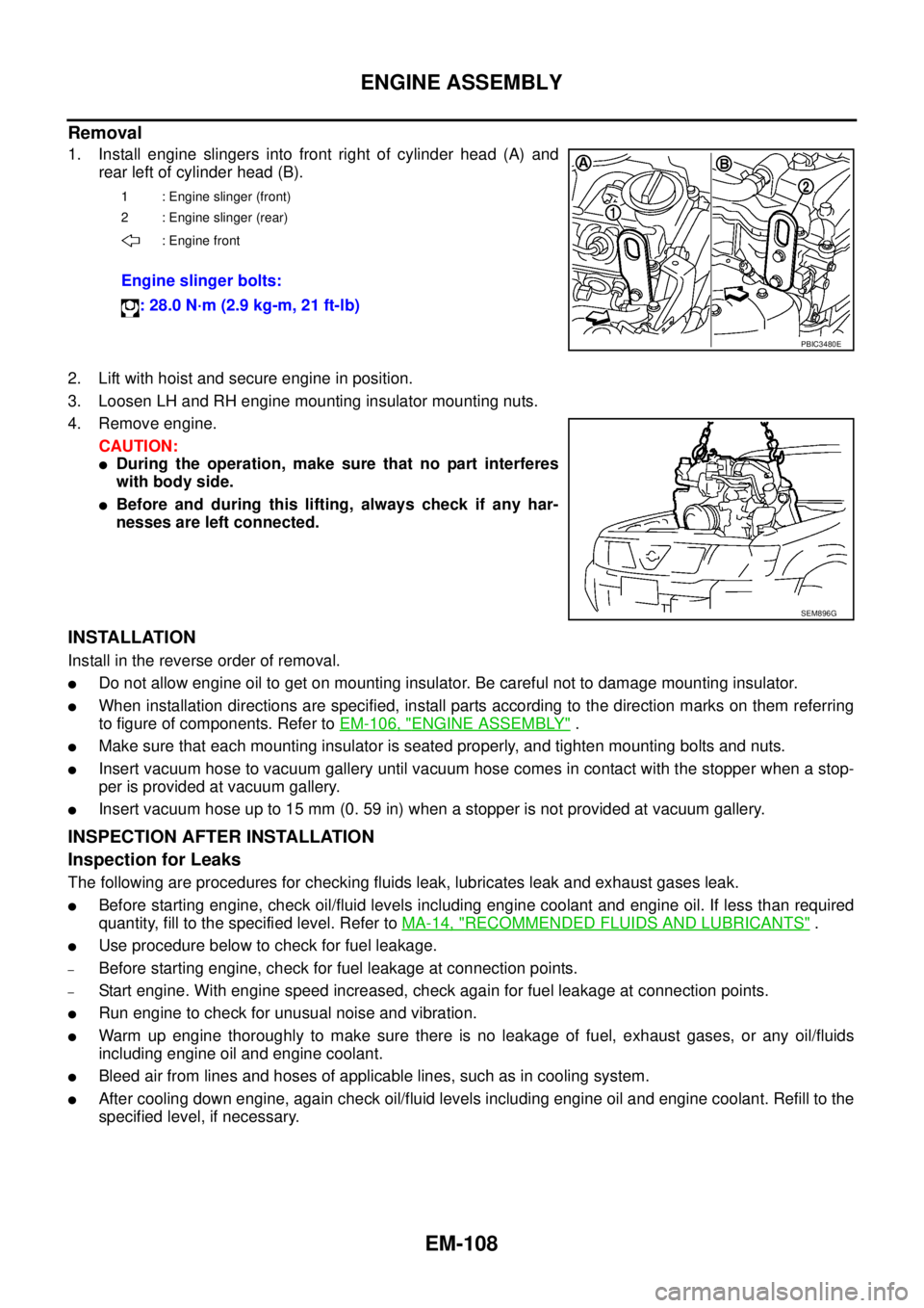
1. Install engine slingers into front right of cylinder head (A) and
rear left of cylinder head (B).
2. Lift with hoist and secure engine in position.
3. Loosen LH and RH engine mounting insulator mounting nuts.
4. Remove engine.
CAUTION:
lDuring the operation, make sure that no part interferes
with body side.
lBefore and during this lifting, always check if any har-
nesses are left connected.
INSTALLATION
Install in the reverse order of removal.
lDo not allow engine oil to get on mounting insulator. Be careful not to damage mounting insulator.
lWhen installation directions are specified, install parts according to the direction marks on them referring
to figure of components. Refer toEM-106, "
ENGINE ASSEMBLY".
lMake sure that each mounting insulator is seated properly, and tighten mounting bolts and nuts.
lInsert vacuum hose to vacuum gallery until vacuum hose comes in contact with the stopper when a stop-
per is provided at vacuum gallery.
lInsert vacuum hose up to 15 mm (0. 59 in) when a stopper is not provided at vacuum gallery.
INSPECTION AFTER INSTALLATION
Inspection for Leaks
The following are procedures for checking fluids leak, lubricates leak and exhaust gases leak.
lBefore starting engine, check oil/fluid levels including engine coolant and engine oil. If less than required
quantity, fill to the specified level. Refer toMA-14, "
RECOMMENDED FLUIDS AND LUBRICANTS".
lUse procedure below to check for fuel leakage.
–Before starting engine, check for fuel leakage at connection points.
–Start engine. With engine speed increased, check again for fuel leakage at connection points.
lRun engine to check for unusual noise and vibration.
lWarm up engine thoroughly to make sure there is no leakage of fuel, exhaust gases, or any oil/fluids
including engine oil and engine coolant.
lBleed air from lines and hoses of applicable lines, such as in cooling system.
lAfter cooling down engine, again check oil/fluid levels including engine oil and engine coolant. Refill to the
specified level, if necessary.
1 : Engine slinger (front)
2 : Engine slinger (rear)
: Engine front
Engine slinger bolts:
: 28.0 N·m (2.9 kg-m, 21 ft-lb)
PBIC3480E
SEM896G
Page 1493 of 3171
CYLINDER BLOCK
EM-111
C
D
E
F
G
H
I
J
K
L
MA
EM
lRefer toGI-10, "Components"for symbol marks in the figure.
Disassembly and AssemblyEBS01E6E
DISASSEMBLY
1. Remove engine from the vehicle. Refer toEM-106, "ENGINE ASSEMBLY".
2. Remove clutch cover and disk. (M/T models) Refer toCL-17,
"CLUTCH DISC, CLUTCH COVER AND FLYWHEEL".
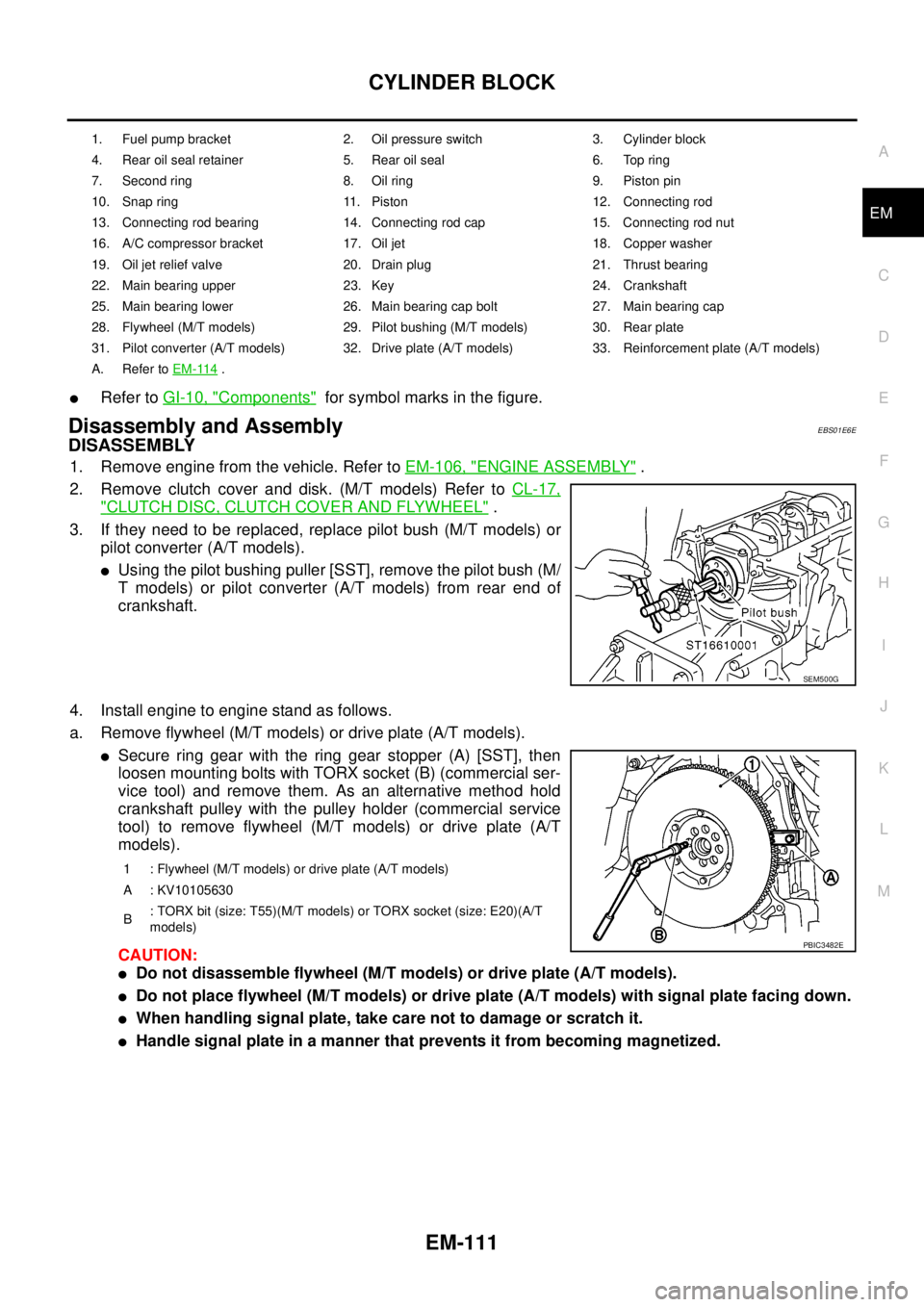
3. If they need to be replaced, replace pilot bush (M/T models) or
pilot converter (A/T models).
lUsing the pilot bushing puller [SST], remove the pilot bush (M/
T models) or pilot converter (A/T models) from rear end of
crankshaft.
4. Install engine to engine stand as follows.
a. Remove flywheel (M/T models) or drive plate (A/T models).
lSecure ring gear with the ring gear stopper (A) [SST], then
loosen mounting bolts with TORX socket (B) (commercial ser-
vice tool) and remove them. As an alternative method hold
crankshaft pulley with the pulley holder (commercial service
tool) to remove flywheel (M/T models) or drive plate (A/T
models).
CAUTION:
lDo not disassemble flywheel (M/T models) or drive plate (A/T models).
lDo not place flywheel (M/T models) or drive plate (A/T models) with signal plate facing down.
lWhen handling signal plate, take care not to damage or scratch it.
lHandle signal plate in a manner that prevents it from becoming magnetized.
1. Fuel pump bracket 2. Oil pressure switch 3. Cylinder block
4. Rear oil seal retainer 5. Rear oil seal 6. Top ring
7. Second ring 8. Oil ring 9. Piston pin
10. Snap ring 11. Piston 12. Connecting rod
13. Connecting rod bearing 14. Connecting rod cap 15. Connecting rod nut
16. A/C compressor bracket 17. Oil jet 18. Copper washer
19. Oil jet relief valve 20. Drain plug 21. Thrust bearing
22. Main bearing upper 23. Key 24. Crankshaft
25. Main bearing lower 26. Main bearing cap bolt 27. Main bearing cap
28. Flywheel (M/T models) 29. Pilot bushing (M/T models) 30. Rear plate
31. Pilot converter (A/T models) 32. Drive plate (A/T models) 33. Reinforcement plate (A/T models)
A. Refer toEM-114
.
SEM500G
1 : Flywheel (M/T models) or drive plate (A/T models)
A : KV10105630
B: TORX bit (size: T55)(M/T models) or TORX socket (size: E20)(A/T
models)
PBIC3482E
Page 1502 of 3171
EM-120
CYLINDER BLOCK
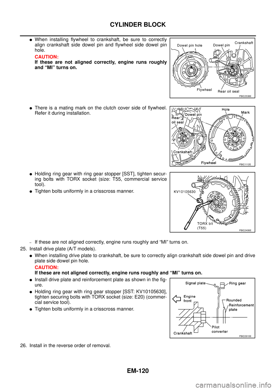
lWhen installing flywheel to crankshaft, be sure to correctly
align crankshaft side dowel pin and flywheel side dowel pin
hole.
CAUTION:
If these are not aligned correctly, engine runs roughly
and “MI” turns on.
lThere is a mating mark on the clutch cover side of flywheel.
Refer it during installation.
lHolding ring gear with ring gear stopper [SST], tighten secur-
ing bolts with TORX socket (size: T55, commercial service
tool).
lTighten bolts uniformly in a crisscross manner.
–If these are not aligned correctly, engine runs roughly and “MI” turns on.
25. Install drive plate (A/T models).
lWhen installing drive plate to crankshaft, be sure to correctly align crankshaft side dowel pin and drive
plate side dowel pin hole.
CAUTION:
If these are not aligned correctly, engine runs roughly and “MI” turns on.
lInstall drive plate and reinforcement plate as shown in the fig-
ure.
lHolding ring gear with ring gear stopper [SST: KV10105630],
tighten securing bolts with TORX socket (size: E20) (commer-
cial service tool).
lTighten bolts uniformly in a crisscross manner.
26. Install in the reverse order of removal.
PBIC2538E
PBIC1112E
PBIC2406E
PBIC0910E
Page 1531 of 3171
EXHAUST SYSTEM
EX-3
C
D
E
F
G
H
I
J
K
L
MA
EX
Removal and InstallationEBS01E7B
CAUTION:
lBe sure to use genuine exhaust system parts or equivalents which are specially designed for heat
resistance, corrosion resistance and shape.
lPerform the operation with the exhaust system fully cooled down because the system will be hot
just after engine stops.
lBe careful not to cut your hand on the insulator edge.
REMOVAL
Separate each connection as necessary.
CAUTION:
Do not disassemble main muffler at the portion “A” shown in the figure.
INSTALLATION
Note the following, and install in the reverse order of removal.
CAUTION:
lAlways replace exhaust gaskets and seal bearings with new ones when reassembling.
lIf insulator is badly deformed, repair or replace it. If deposits such as mud pile up on insulator,
remove them.
lWhen installing insulator avoid large gaps or interference between insulator and each exhaust
pipe.
lRemove deposits from the sealing surface of each connection. Connect them securely to avoid
gas leakage.
lTemporarily tighten mounting nuts on the exhaust manifold side and mounting bolts on the vehi-
cle side. Check each part for unusual interference, and then tighten them to the specified torque.
lWhen installing each mounting rubber, avoid twisting or unusual extension in up/down and right/
left directions.
lInstall tail tube to main muffler as follows.
Ta i l t u b e
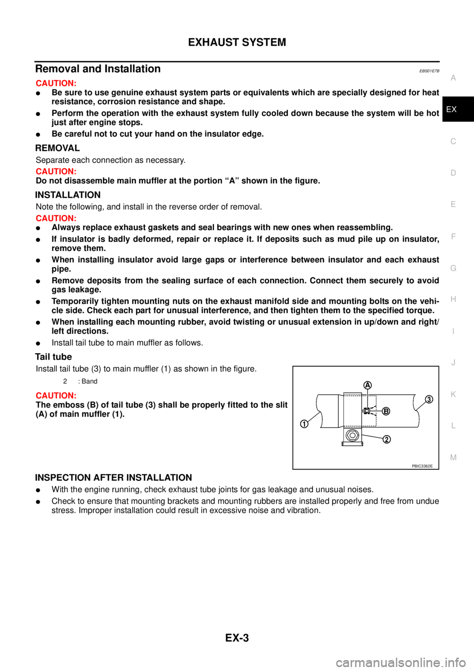
Install tail tube (3) to main muffler (1) as shown in the figure.
CAUTION:
The emboss (B) of tail tube (3) shall be properly fitted to the slit
(A) of main muffler (1).
INSPECTION AFTER INSTALLATION
lWith the engine running, check exhaust tube joints for gas leakage and unusual noises.
lCheck to ensure that mounting brackets and mounting rubbers are installed properly and free from undue
stress. Improper installation could result in excessive noise and vibration.
2:Band
PBIC3362E
Page 1540 of 3171
FAX-8
DRIVE SHAFT
INSTALLATION
Installation is in the reverse order of removal.
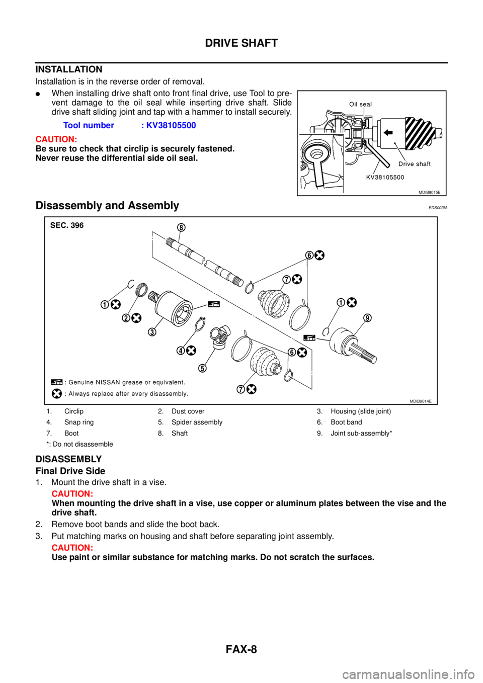
lWhen installing drive shaft onto front final drive, use Tool to pre-
vent damage to the oil seal while inserting drive shaft. Slide
drive shaft sliding joint and tap with a hammer to install securely.
CAUTION:
Be sure to check that circlip is securely fastened.
Never reuse the differential side oil seal.
Disassembly and AssemblyEDS003IA
DISASSEMBLY
Final Drive Side
1. Mount the drive shaft in a vise.
CAUTION:
When mounting the drive shaft in a vise, use copper or aluminum plates between the vise and the
drive shaft.
2. Remove boot bands and slide the boot back.
3. Put matching marks on housing and shaft before separating joint assembly.
CAUTION:
Use paint or similar substance for matching marks. Do not scratch the surfaces.Tool number : KV38105500
MDIB9015E
1. Circlip 2. Dust cover 3. Housing (slide joint)
4. Snap ring 5. Spider assembly 6. Boot band
7. Boot 8. Shaft 9. Joint sub-assembly*
*: Do not disassemble
MDIB9014E