Page 1542 of 3171
FAX-10
DRIVE SHAFT
Inner Race
lCheck the ball sliding surface for any compression scars, cracks, or fractures.
lCheck for any damage to the serrated part.
ASSEMBLY
Final Drive Side
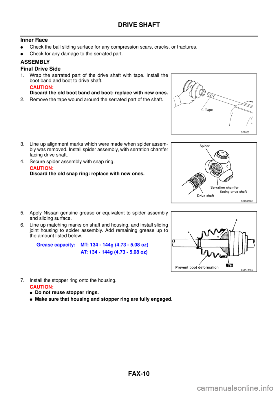
1. Wrap the serrated part of the drive shaft with tape. Install the
boot band and boot to drive shaft.
CAUTION:
Discard the old boot band and boot: replace with new ones.
2. Remove the tape wound around the serrated part of the shaft.
3. Line up alignment marks which were made when spider assem-
bly was removed. Install spider assembly, with serration chamfer
facing drive shaft.
4. Secure spider assembly with snap ring.
CAUTION:
Discard the old snap ring: replace with new ones.
5. Apply Nissan genuine grease or equivalent to spider assembly
and sliding surface.
6. Line up matching marks on shaft and housing, and install sliding
joint housing to spider assembly. Add remaining grease up to
the amount listed below.
7. Install the stopper ring onto the housing.
CAUTION:
lDo not reuse stopper rings.
lMake sure that housing and stopper ring are fully engaged.
SFA800
SDIA0598E
Grease capacity: MT: 134 - 144g (4.73 - 5.08 oz)
AT: 134 - 144g (4.73 - 5.08 oz)
SDIA1446E
Page 1543 of 3171
DRIVE SHAFT
FAX-11
C
E
F
G
H
I
J
K
L
MA
B
FA X
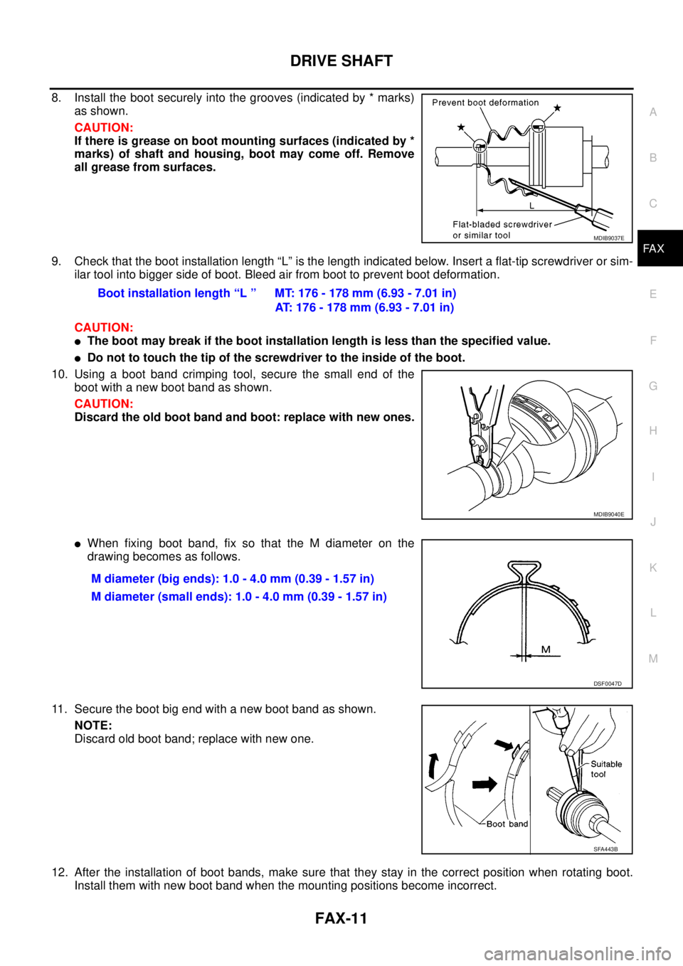
8. Install the boot securely into the grooves (indicated by * marks)
as shown.
CAUTION:
If there is grease on boot mounting surfaces (indicated by *
marks) of shaft and housing, boot may come off. Remove
all grease from surfaces.
9. Check that the boot installation length “L” is the length indicated below. Insert a flat-tip screwdriver or sim-
ilar tool into bigger side of boot. Bleed air from boot to prevent boot deformation.
CAUTION:
lThe boot may break if the boot installation length is less than the specified value.
lDo not to touch the tip of the screwdriver to the inside of the boot.
10. Usingabootbandcrimpingtool,securethesmallendofthe
boot with a new boot band as shown.
CAUTION:
Discard the old boot band and boot: replace with new ones.
lWhen fixing boot band, fix so that the M diameter on the
drawing becomes as follows.
11. Secure the boot big end with a new boot band as shown.
NOTE:
Discard old boot band; replace with new one.
12. After the installation of boot bands, make sure that they stay in the correct position when rotating boot.
Install them with new boot band when the mounting positions become incorrect.
MDIB9037E
Boot installation length “L ” MT: 176 - 178 mm (6.93 - 7.01 in)
AT: 176 - 178 mm (6.93 - 7.01 in)
MDIB9040E
M diameter (big ends): 1.0 - 4.0 mm (0.39 - 1.57 in)
M diameter (small ends): 1.0 - 4.0 mm (0.39 - 1.57 in)
DSF0047D
SFA443B
Page 1544 of 3171
FAX-12
DRIVE SHAFT
13. Install circlip and dust cover to housing.
NOTE:
Do not reuse circlip and dust cover.
Wheel Side
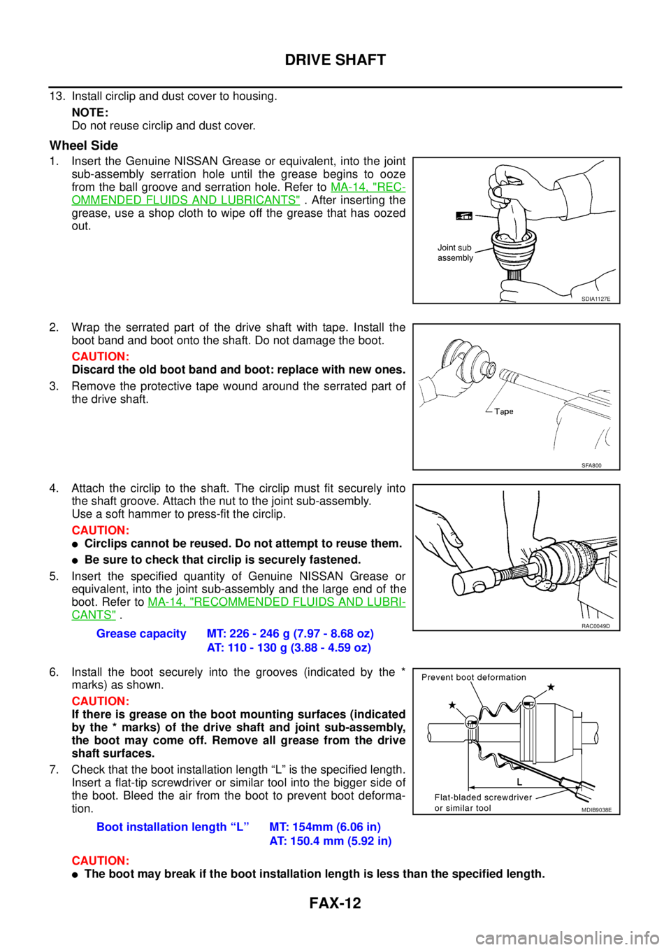
1. Insert the Genuine NISSAN Grease or equivalent, into the joint
sub-assembly serration hole until the grease begins to ooze
from the ball groove and serration hole. Refer toMA-14, "
REC-
OMMENDED FLUIDS AND LUBRICANTS". After inserting the
grease, use a shop cloth to wipe off the grease that has oozed
out.
2. Wrap the serrated part of the drive shaft with tape. Install the
boot band and boot onto the shaft. Do not damage the boot.
CAUTION:
Discard the old boot band and boot: replace with new ones.
3. Remove the protective tape wound around the serrated part of
the drive shaft.
4. Attach the circlip to the shaft. The circlip must fit securely into
the shaft groove. Attach the nut to the joint sub-assembly.
Useasofthammertopress-fitthecirclip.
CAUTION:
lCirclips cannot be reused. Do not attempt to reuse them.
lBe sure to check that circlip is securely fastened.
5. Insert the specified quantity of Genuine NISSAN Grease or
equivalent, into the joint sub-assembly and the large end of the
boot. Refer toMA-14, "
RECOMMENDED FLUIDS AND LUBRI-
CANTS".
6. Install the boot securely into the grooves (indicated by the *
marks) as shown.
CAUTION:
If there is grease on the boot mounting surfaces (indicated
by the * marks) of the drive shaft and joint sub-assembly,
the boot may come off. Remove all grease from the drive
shaft surfaces.
7. Check that the boot installation length “L” is the specified length.
Insert a flat-tip screwdriver or similar tool into the bigger side of
the boot. Bleed the air from the boot to prevent boot deforma-
tion.
CAUTION:
lThe boot may break if the boot installation length is less than the specified length.
SDIA1127E
SFA800
Grease capacity MT: 226 - 246 g (7.97 - 8.68 oz)
AT: 110 - 130 g (3.88 - 4.59 oz)RAC0049D
Boot installation length “L” MT: 154mm (6.06 in)
AT: 150.4 mm (5.92 in)
MDIB9038E
Page 1545 of 3171
DRIVE SHAFT
FAX-13
C
E
F
G
H
I
J
K
L
MA
B
FA X
lDo not contact inside surface of boot with the tip of the screwdriver.
8. Secure small end of the boot using a new boot band and a boot
band crimping tool as shown.
CAUTION:
Discard the old boot band and boot: replace with new ones.
lWhen fixing boot band, fix so that the M diameter on the
drawing becomes as follows.
9. Secure the boot big end with a new boot band as shown.
NOTE:
Discard old boot band; replace with new one.
10. After the installation of boot bands, rotate the boot to check that
it is positioned correctly. If the boot is not positioned correctly,
remove the old boot bands then reposition the boot and secure
the boot with new boot bands.Tool number : KV40107300
MDIB9040E
M diameter (big ends): 1.0 - 4.0 mm (0.39 - 1.57 in)
M diameter (small ends): 1.0 - 4.0 mm (0.39 - 1.57 in)
DSF0047D
SFA443B
Page 1562 of 3171
FFD-16
FRONT FINAL DRIVE ASSEMBLY
CAUTION:
Do not pull on the ABS sensor harness.
4. Support the lower link using a suitable jack.
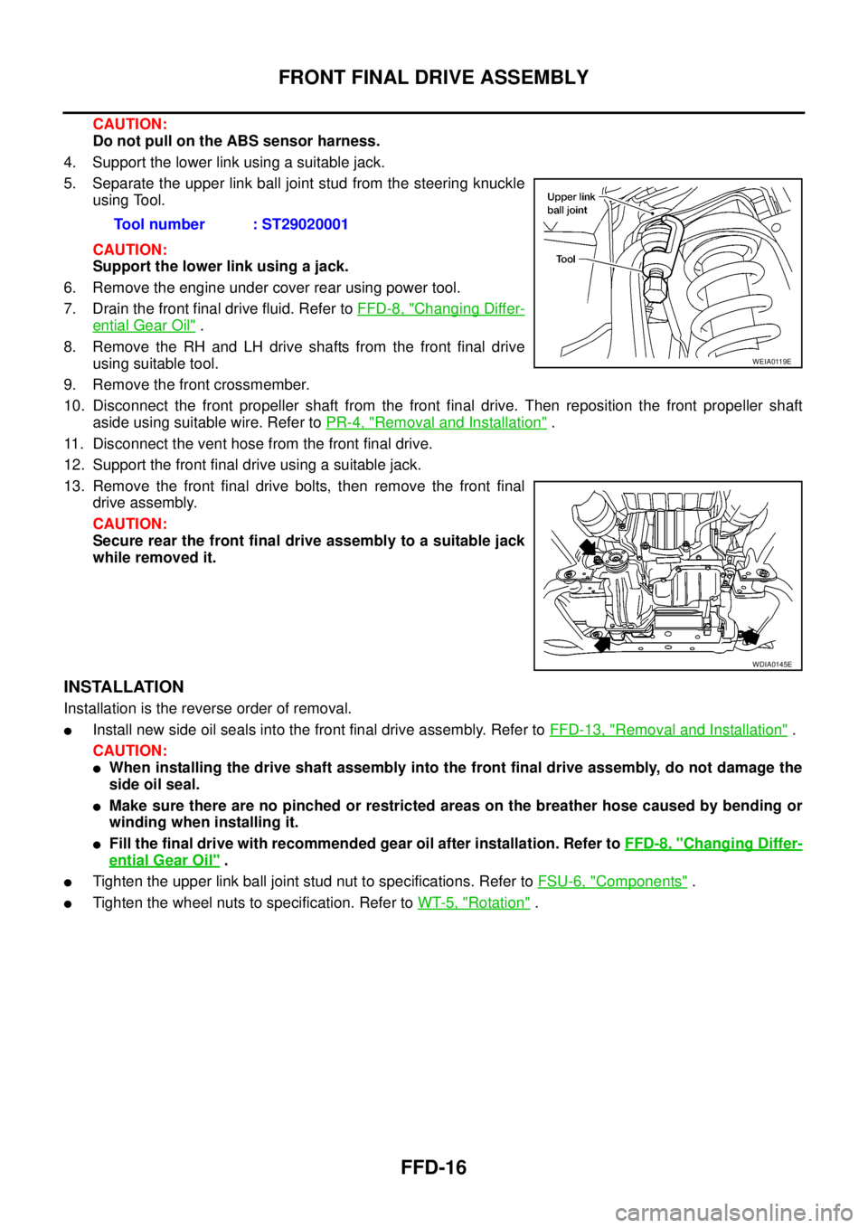
5. Separate the upper link ball joint stud from the steering knuckle
using Tool.
CAUTION:
Support the lower link using a jack.
6. Remove the engine under cover rear using power tool.
7. Drain the front final drive fluid. Refer toFFD-8, "
Changing Differ-
ential Gear Oil".
8. Remove the RH and LH drive shafts from the front final drive
using suitable tool.
9. Remove the front crossmember.
10. Disconnect the front propeller shaft from the front final drive. Then reposition the front propeller shaft
aside using suitable wire. Refer toPR-4, "
Removal and Installation".
11. Disconnect the vent hose from the front final drive.
12. Support the front final drive using a suitable jack.
13. Remove the front final drive bolts, then remove the front final
drive assembly.
CAUTION:
Secure rear the front final drive assembly to a suitable jack
while removed it.
INSTALLATION
Installation is the reverse order of removal.
lInstall new side oil seals into the front final drive assembly. Refer toFFD-13, "Removal and Installation".
CAUTION:
lWhen installing the drive shaft assembly into the front final drive assembly, do not damage the
side oil seal.
lMake sure there are no pinched or restricted areas on the breather hose caused by bending or
winding when installing it.
lFill the final drive with recommended gear oil after installation. Refer toFFD-8, "Changing Differ-
ential Gear Oil".
lTighten the upper link ball joint stud nut to specifications. Refer toFSU-6, "Components".
lTighten the wheel nuts to specification. Refer toWT-5, "Rotation". Tool number : ST29020001
WEIA0119E
WDIA0145E
Page 1587 of 3171
FUEL SYSTEM
FL-3
C
D
E
F
G
H
I
J
K
L
MA
FL
FUEL SYSTEMPFP:17503
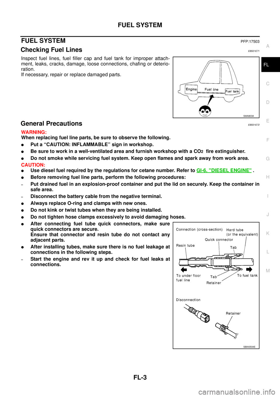
Checking Fuel LinesEBS01E71
Inspect fuel lines, fuel filler cap and fuel tank for improper attach-
ment, leaks, cracks, damage, loose connections, chafing or deterio-
ration.
If necessary, repair or replace damaged parts.
General PrecautionsEBS01E72
WARNING:
When replacing fuel line parts, be sure to observe the following.
lPut a “CAUTION: INFLAMMABLE” sign in workshop.
lBe sure to work in a well-ventilated area and furnish workshop with a CO2fire extinguisher.
lDo not smoke while servicing fuel system. Keep open flames and spark away from work area.
CAUTION:
lUse diesel fuel required by the regulations for cetane number. Refer toGI-6, "DIESEL ENGINE".
lBefore removing fuel line parts, perform the following procedures:
–Put drained fuel in an explosion-proof container and put the lid on securely. Keep the container in
safe area.
–Disconnect the battery cable from the negative terminal.
lAlways replace O-ring and clamps with new ones.
lDo not kink or twist tubes when they are being installed.
lDo not tighten hose clamps excessively to avoid damaging hoses.
lAfter connecting fuel tube quick connectors, make sure
quick connectors are secure.
Ensure that connector and resin tube do not contact any
adjacent parts.
lAfter installing tubes, make sure there is no fuel leakage at
connections in the following steps.
–Start the engine and rev it up and check for fuel leaks at
connections.
SMA803A
SBIA0504E
Page 1596 of 3171
FL-12
FUEL TANK
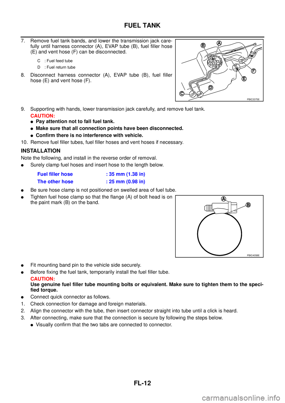
7. Remove fuel tank bands, and lower the transmission jack care-
fully until harness connector (A), EVAP tube (B), fuel filler hose
(E) and vent hose (F) can be disconnected.
8. Disconnect harness connector (A), EVAP tube (B), fuel filler
hose (E) and vent hose (F).
9. Supporting with hands, lower transmission jack carefully, and remove fuel tank.
CAUTION:
lPay attention not to fall fuel tank.
lMake sure that all connection points have been disconnected.
lConfirm there is no interference with vehicle.
10. Remove fuel filler tubes, fuel filler hoses and vent hoses if necessary.
INSTALLATION
Note the following, and install in the reverse order of removal.
lSurely clamp fuel hoses and insert hose to the length below.
lBe sure hose clamp is not positioned on swelled area of fuel tube.
lTighten fuel hose clamp so that the flange (A) of bolt head is on
the paint mark (B) on the band.
lFit mounting band pin to the vehicle side securely.
lBefore fixing the fuel tank, temporarily install the fuel filler tube.
CAUTION:
Use genuine fuel filler tube mounting bolts or equivalent. Make sure to tighten them to the speci-
fied torque.
lConnect quick connector as follows.
1. Check connection for damage and foreign materials.
2. Align the connector with the tube, then insert connector straight into tube until a click is heard.
3. After connecting, make sure that the connection is secure by following the steps below.
lVisually confirm that the two tabs are connected to connector.
C : Fuel feed tube
D : Fuel return tube
PBIC3375E
Fuel filler hose : 35 mm (1.38 in)
The other hose : 25 mm (0.98 in)
PBIC4058E
Page 1597 of 3171
FUEL TANK
FL-13
C
D
E
F
G
H
I
J
K
L
MA
FL
lPull the tube and connector to make sure they are securely
connected.
INSPECTION AFTER INSTALLATION
Make sure there is no fuel leakage at connections in the following step.
lStart engine and rev it up and make sure there is no fuel leakage at connections.
PBIC1653E