2005 NISSAN NAVARA reset sun roof
[x] Cancel search: reset sun roofPage 1687 of 3171

GW-1
GLASSES, WINDOW SYSTEM & MIRRORS
IBODY
CONTENTS
C
D
E
F
G
H
J
K
L
M
SECTIONGW
A
B
GW
GLASSES, WINDOW SYSTEM & MIRRORS
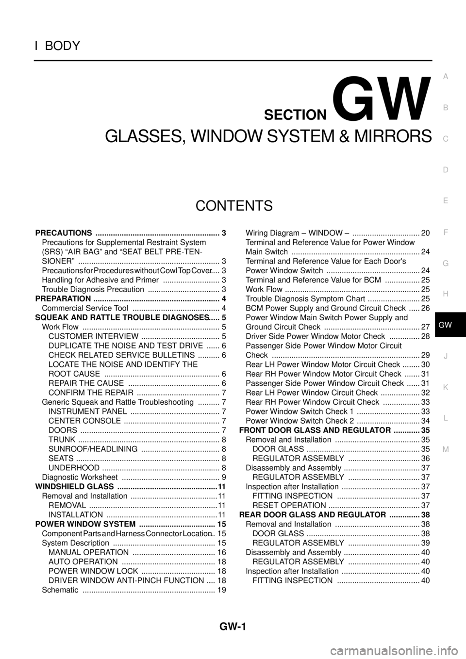
PRECAUTIONS .......................................................... 3
Precautions for Supplemental Restraint System
(SRS)“AIRBAG”and“SEATBELTPRE-TEN-
SIONER” .................................................................. 3
Precautions for Procedures without Cowl Top Cover..... 3
Handling for Adhesive and Primer ........................... 3
Trouble Diagnosis Precaution .................................. 3
PREPARATION ........................................................... 4
Commercial Service Tool ......................................... 4
SQUEAK AND RATTLE TROUBLE DIAGNOSES..... 5
Work Flow ................................................................ 5
CUSTOMER INTERVIEW ..................................... 5
DUPLICATE THE NOISE AND TEST DRIVE ....... 6
CHECK RELATED SERVICE BULLETINS ........... 6
LOCATE THE NOISE AND IDENTIFY THE
ROOT CAUSE ...................................................... 6
REPAIR THE CAUSE ........................................... 6
CONFIRM THE REPAIR ....................................... 7
Generic Squeak and Rattle Troubleshooting ........... 7
INSTRUMENT PANEL .......................................... 7
CENTER CONSOLE ............................................. 7
DOORS ................................................................. 7
TRUNK .................................................................. 8
SUNROOF/HEADLINING ..................................... 8
SEATS ................................................................... 8
UNDERHOOD ....................................................... 8
Diagnostic Worksheet .............................................. 9
WINDSHIELD GLASS ...............................................11
Removal and Installation ......................................... 11
REMOVAL ............................................................ 11
INSTALLATION .................................................... 11
POWER WINDOW SYSTEM .................................... 15
Component Parts and Harness Connector Location... 15
System Description ................................................ 15
MANUAL OPERATION ....................................... 16
AUTO OPERATION ............................................ 18
POWER WINDOW LOCK ................................... 18
DRIVER WINDOW ANTI-PINCH FUNCTION ..... 18
Schematic .............................................................. 19Wiring Diagram – WINDOW – ................................ 20
Terminal and Reference Value for Power Window
Main Switch ............................................................ 24
Terminal and Reference Value for Each Door's
Power Window Switch ............................................ 24
Terminal and Reference Value for BCM ................. 25
Work Flow ............................................................... 25
Trouble Diagnosis Symptom Chart ......................... 25
BCM Power Supply and Ground Circuit Check ...... 26
Power Window Main Switch Power Supply and
Ground Circuit Check ............................................. 27
Driver Side Power Window Motor Check ............... 28
Passenger Side Power Window Motor Circuit
Check ..................................................................... 29
Rear LH Power Window Motor Circuit Check ......... 30
Rear RH Power Window Motor Circuit Check ........ 31
Passenger Side Power Window Circuit Check ....... 31
Rear LH Power Window Circuit Check ................... 32
Rear RH Power Window Circuit Check .................. 33
Power Window Switch Check 1 .............................. 33
Power Window Switch Check 2 .............................. 34
FRONT DOOR GLASS AND REGULATOR ............. 35
Removal and Installation ........................................ 35
DOOR GLASS ..................................................... 35
REGULATOR ASSEMBLY .................................. 36
Disassembly and Assembly .................................... 37
REGULATOR ASSEMBLY .................................. 37
Inspection after Installation ..................................... 37
FITTING INSPECTION ....................................... 37
RESET OPERATION ........................................... 37
REAR DOOR GLASS AND REGULATOR ............... 38
Removal and Installation ........................................ 38
DOOR GLASS ..................................................... 38
REGULATOR ASSEMBLY .................................. 39
Disassembly and Assembly .................................... 40
REGULATOR ASSEMBLY .................................. 40
Inspection after Installation ..................................... 40
FITTING INSPECTION ....................................... 40
Page 2678 of 3171

RF-1
ROOF
IBODY
CONTENTS
C
D
E
F
G
H
J
K
L
M
SECTIONRF
A
B
RF
ROOF
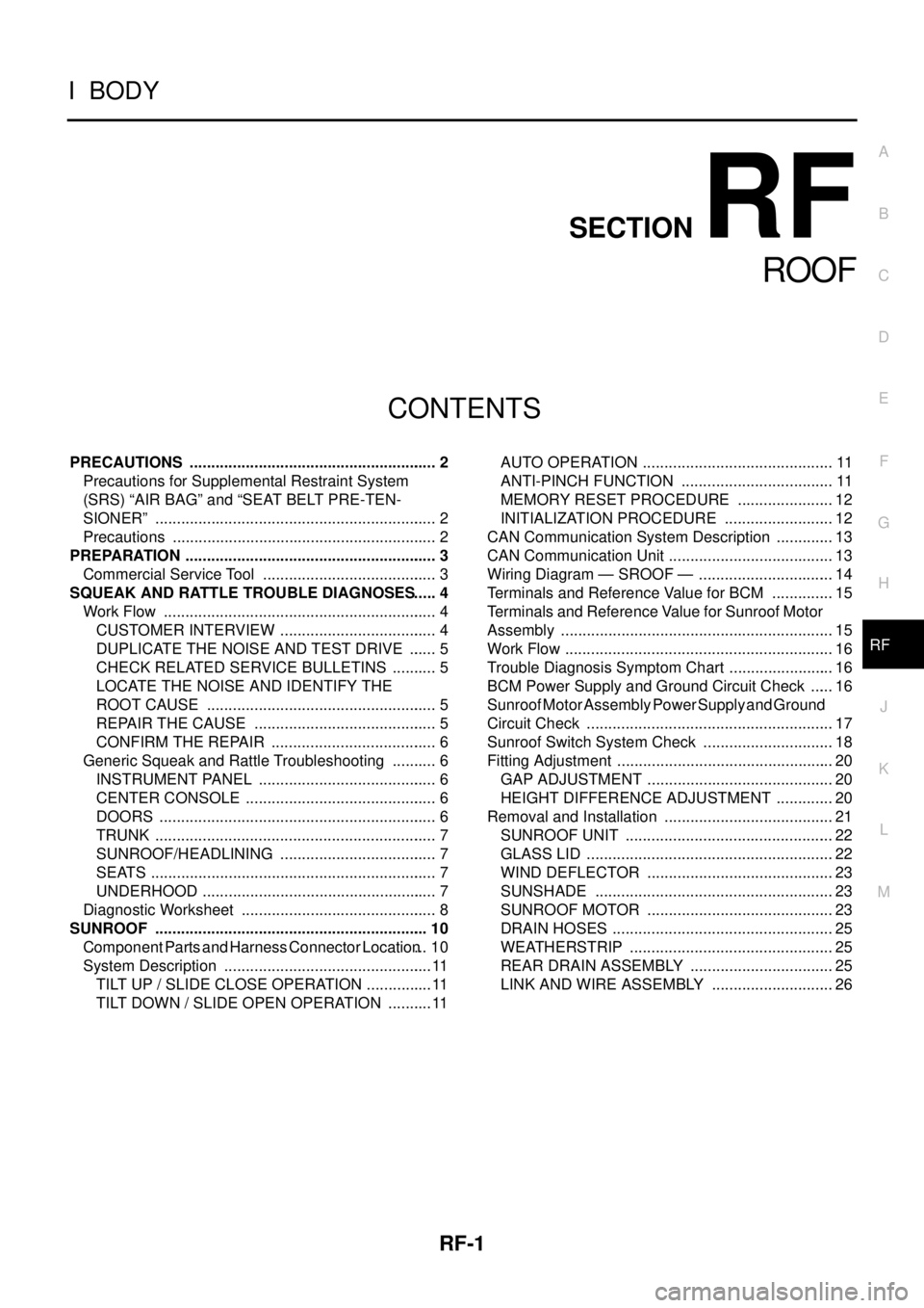
PRECAUTIONS .......................................................... 2
Precautions for Supplemental Restraint System
(SRS)“AIRBAG”and“SEATBELTPRE-TEN-
SIONER” .................................................................. 2
Precautions .............................................................. 2
PREPARATION ........................................................... 3
Commercial Service Tool ......................................... 3
SQUEAK AND RATTLE TROUBLE DIAGNOSES..... 4
Work Flow ................................................................ 4
CUSTOMER INTERVIEW ..................................... 4
DUPLICATE THE NOISE AND TEST DRIVE ....... 5
CHECK RELATED SERVICE BULLETINS ........... 5
LOCATE THE NOISE AND IDENTIFY THE
ROOT CAUSE ...................................................... 5
REPAIR THE CAUSE ........................................... 5
CONFIRM THE REPAIR ....................................... 6
Generic Squeak and Rattle Troubleshooting ........... 6
INSTRUMENT PANEL .......................................... 6
CENTER CONSOLE ............................................. 6
DOORS ................................................................. 6
TRUNK .................................................................. 7
SUNROOF/HEADLINING ..................................... 7
SEATS ................................................................... 7
UNDERHOOD ....................................................... 7
Diagnostic Worksheet .............................................. 8
SUNROOF ................................................................ 10
Component Parts and Harness Connector Location... 10
System Description ................................................. 11
TILT UP / SLIDE CLOSE OPERATION ................ 11
TILT DOWN / SLIDE OPEN OPERATION ........... 11AUTO OPERATION ............................................. 11
ANTI-PINCH FUNCTION .................................... 11
MEMORY RESET PROCEDURE ....................... 12
INITIALIZATION PROCEDURE .......................... 12
CAN Communication System Description .............. 13
CAN Communication Unit ....................................... 13
Wiring Diagram — SROOF — ................................ 14
Terminals and Reference Value for BCM ............... 15
Terminals and Reference Value for Sunroof Motor
Assembly ................................................................ 15
Work Flow ............................................................... 16
Trouble Diagnosis Symptom Chart ......................... 16
BCM Power Supply and Ground Circuit Check ...... 16
Sunroof Motor Assembly Power Supply and Ground
Circuit Check .......................................................... 17
Sunroof Switch System Check ............................... 18
Fitting Adjustment ................................................... 20
GAP ADJUSTMENT ............................................ 20
HEIGHT DIFFERENCE ADJUSTMENT .............. 20
Removal and Installation ........................................ 21
SUNROOF UNIT ................................................. 22
GLASS LID .......................................................... 22
WIND DEFLECTOR ............................................ 23
SUNSHADE ........................................................ 23
SUNROOF MOTOR ............................................ 23
DRAIN HOSES .................................................... 25
WEATHERSTRIP ................................................ 25
REAR DRAIN ASSEMBLY .................................. 25
LINK AND WIRE ASSEMBLY ............................. 26
Page 2689 of 3171

RF-12
SUNROOF
MEMORY RESET PROCEDURE
1. Please observe the following instructions while confirming the sunroof operation.
NOTE:
Do not disconnect the electronic power while the sunroof is operating or within 5 seconds after the sunroof
stops. (to wipe-out the memory of lid position and operating friction.)
2. Initialization of system should be conducted after the following conditions.
lWhen the battery is out or connector is disconnected while sunroof is operating or within 5 seconds
after sunroof stops.
lWhen the sunroof motor is changed.
lWhen an emergency handle is used.
lWhen the sunroof does not operate normally. (Incomplete initialization conditions)
INITIALIZATION PROCEDURE
If sunroof does not close or open normally, use following procedure to return sunroof operation to normal.
1. Close sunroof if it is not in close position. It may be necessary to repeatedly push TILT UP/SLIDE CLOSE
switch to close sunroof.
2. Tilt up sunroof, and release TILT UP/SLIDE CLOSE switch once.
3. Keep pushing TILT UP/SLIDE CLOSE switch. After 10seconds, glass lid will back up a few millimeters.
then will be stopped at normal tilt up position.
(Keep pushing TILT UP/SLIDE CLOSE switch during this operation.)
4. Within first 10 seconds of releasing TILT UP/SLIDE CLOSE switch, keep pushing TILT UP/SLIDE CLOSE
switch again. After 4 seconds, glass lid will be automatically TILT DOWN®SLIDE OPEN®SLIDE
CLOSE.
(Keep pushing TILT UP/SLIDE CLOSE switch during this operation.)
5. After glass lid stops, release TILT UP/SLIDE CLOSE switch later 0.5 seconds.
6. Initializing procedure is completed. Confirm proper operation of sunroof (slide open, slide close, tilt up, tilt
down).