2005 NISSAN NAVARA jump cable
[x] Cancel search: jump cablePage 1183 of 3171
DTC P0563 BATTERY VOLTAGE
EC-203
C
D
E
F
G
H
I
J
K
L
MA
EC
DTC P0563 BATTERY VOLTAGEPFP:24410
On Board Diagnosis LogicEBS01KI1
The MI will not light up for this self-diagnosis.
DTC Confirmation ProcedureEBS01KI2
NOTE:
If DTC Confirmation Procedure has been previously conducted, always turn ignition switch OFF and wait at
least 10 seconds before conducting the next test.
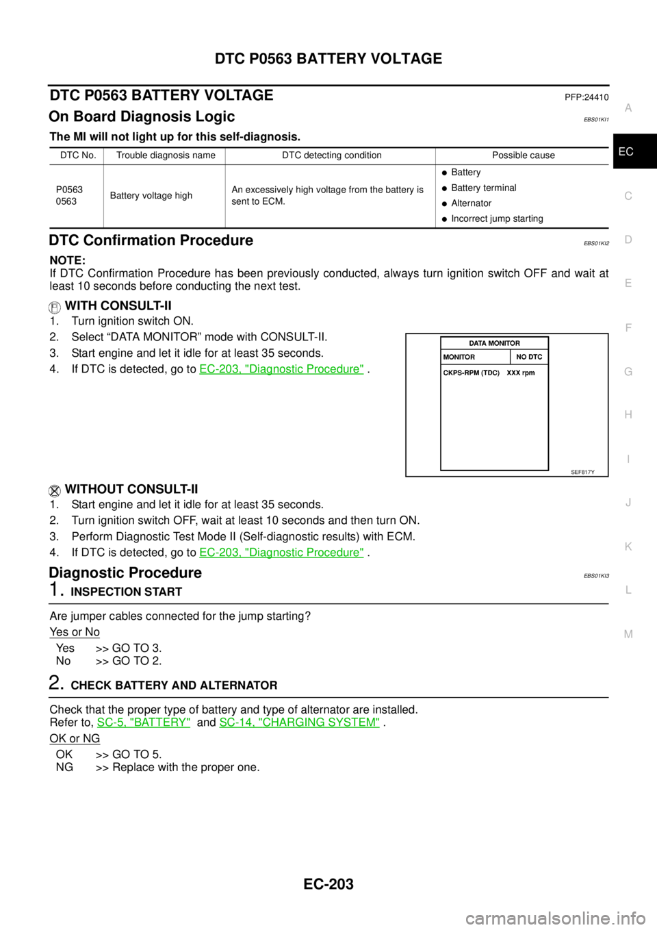
WITH CONSULT-II
1. Turn ignition switch ON.
2. Select “DATA MONITOR” mode with CONSULT-II.
3. Start engine and let it idle for at least 35 seconds.
4. If DTC is detected, go toEC-203, "
Diagnostic Procedure".
WITHOUT CONSULT-II
1. Start engine and let it idle for at least 35 seconds.
2. Turn ignition switch OFF, wait at least 10 seconds and then turn ON.
3. Perform Diagnostic Test Mode II (Self-diagnostic results) with ECM.
4. If DTC is detected, go toEC-203, "
Diagnostic Procedure".
Diagnostic ProcedureEBS01KI3
1.INSPECTION START
Are jumper cables connected for the jump starting?
Ye s o r N o
Ye s > > G O T O 3 .
No >> GO TO 2.
2.CHECK BATTERY AND ALTERNATOR
Check that the proper type of battery and type of alternator are installed.
Refer to,SC-5, "
BATTERY"andSC-14, "CHARGING SYSTEM".
OK or NG
OK >> GO TO 5.
NG >> Replace with the proper one.
DTC No. Trouble diagnosis name DTC detecting condition Possible cause
P0563
0563Battery voltage highAn excessively high voltage from the battery is
sent to ECM.
lBattery
lBattery terminal
lAlternator
lIncorrect jump starting
SEF817Y
Page 1184 of 3171
EC-204
DTC P0563 BATTERY VOLTAGE
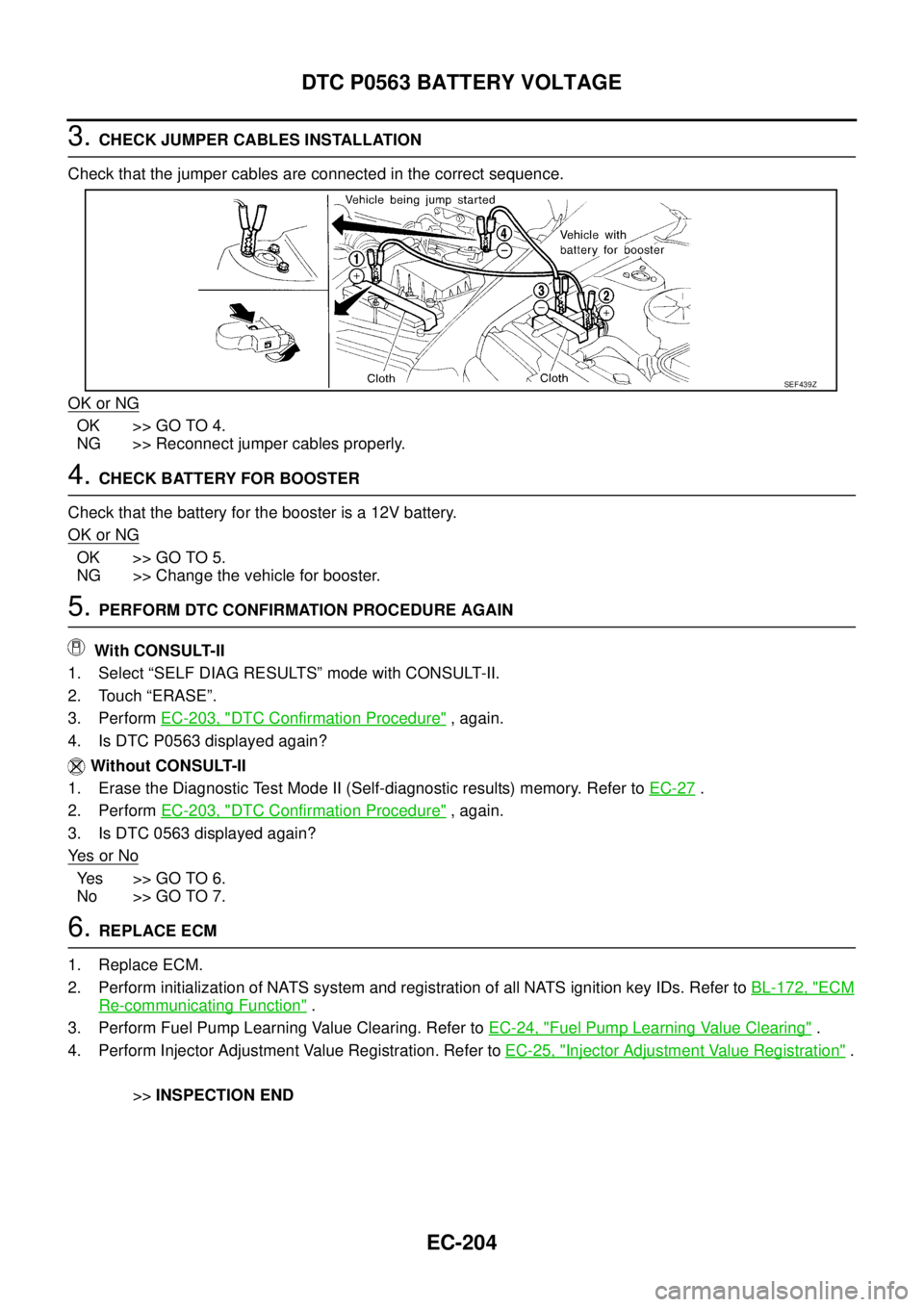
3.CHECK JUMPER CABLES INSTALLATION
Check that the jumper cables are connected in the correct sequence.
OK or NG
OK >> GO TO 4.
NG >> Reconnect jumper cables properly.
4.CHECK BATTERY FOR BOOSTER
Check that the battery for the booster is a 12V battery.
OK or NG
OK >> GO TO 5.
NG >> Change the vehicle for booster.
5.PERFORM DTC CONFIRMATION PROCEDURE AGAIN
With CONSULT-II
1. Select “SELF DIAG RESULTS” mode with CONSULT-II.
2. Touch “ERASE”.
3. PerformEC-203, "
DTC Confirmation Procedure",again.
4. Is DTC P0563 displayed again?
Without CONSULT-II
1. Erase the Diagnostic Test Mode II (Self-diagnostic results) memory. Refer toEC-27
.
2. PerformEC-203, "
DTC Confirmation Procedure",again.
3. Is DTC 0563 displayed again?
Ye s o r N o
Yes >>GOTO6.
No >> GO TO 7.
6.REPLACE ECM
1. Replace ECM.
2. Perform initialization of NATS system and registration of all NATS ignition key IDs. Refer toBL-172, "
ECM
Re-communicating Function".
3. Perform Fuel Pump Learning Value Clearing. Refer toEC-24, "
Fuel Pump Learning Value Clearing".
4. Perform Injector Adjustment Value Registration. Refer toEC-25, "
Injector Adjustment Value Registration".
>>INSPECTION END
SEF439Z
Page 1626 of 3171
GI-4
PRECAUTIONS
For this reason, if the battery is disconnected or if the battery is discharged, the steering wheel will lock and
steering wheel rotation will become impossible.
If steering wheel rotation is required when battery power is interrupted, follow the procedure below before
starting the repair operation.
OPERATION PROCEDURE
1. Connect both battery cables.
NOTE:
Supply power using jumper cables if battery is discharged.
2. Use the Intelligent Key or mechanical key to turn the ignition switch to the²ACC²position. At this time, the
steering lock will be released.
3. Disconnect both battery cables. The steering lock will remain released and the steering wheel can be
rotated.
4. Perform the necessary repair operation.
5. When the repair work is completed, return the ignition switch to the²LOCK²position before connecting
the battery cables. (At this time, the steering lock mechanism will engage.)
6. Perform a self-diagnosis check of all control units using CONSULT-II.
General PrecautionsEAS001GJ
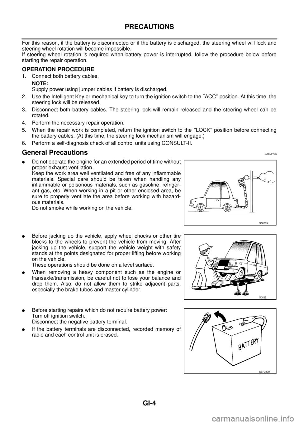
lDo not operate the engine for an extended period of time without
proper exhaust ventilation.
Keep the work area well ventilated and free of any inflammable
materials. Special care should be taken when handling any
inflammable or poisonous materials, such as gasoline, refriger-
ant gas, etc. When working in a pit or other enclosed area, be
sure to properly ventilate the area before working with hazard-
ous materials.
Do not smoke while working on the vehicle.
lBefore jacking up the vehicle, apply wheel chocks or other tire
blocks to the wheels to prevent the vehicle from moving. After
jacking up the vehicle, support the vehicle weight with safety
stands at the points designated for proper lifting before working
on the vehicle.
These operations should be done on a level surface.
lWhen removing a heavy component such as the engine or
transaxle/transmission, be careful not to lose your balance and
drop them. Also, do not allow them to strike adjacent parts,
especially the brake tubes and master cylinder.
lBefore starting repairs which do not require battery power:
Turn off ignition switch.
Disconnect the negative battery terminal.
lIf the battery terminals are disconnected, recorded memory of
radio and each control unit is erased.
SGI285
SGI231
SEF289H
Page 1650 of 3171
GI-28
SERVICE INFORMATION FOR ELECTRICAL INCIDENT
VOLTAGE CHECK METHOD
To help in understanding the diagnosis of open circuits please refer to the previous schematic.
In any powered circuit, an open can be found by methodically checking the system for the presence of voltage.
This is done by switching the DMM to the voltage function.
lConnect one probe of the DMM to a known good ground.
lBegin probing at one end of the circuit and work your way to the other end.
lWith SW1 open, probe at SW1 to check for voltage.
voltage; open is further down the circuit than SW1.
no voltage; open is between fuse block and SW1 (point A).
lClose SW1 and probe at relay.
voltage; open is further down the circuit than the relay.
no voltage; open is between SW1 and relay (point B).
lClose the relay and probe at the solenoid.
voltage; open is further down the circuit than the solenoid.
no voltage; open is between relay and solenoid (point C).
Any powered circuit can be diagnosed using the approach in the previous example.
Testing for “Shorts” in the Circuit
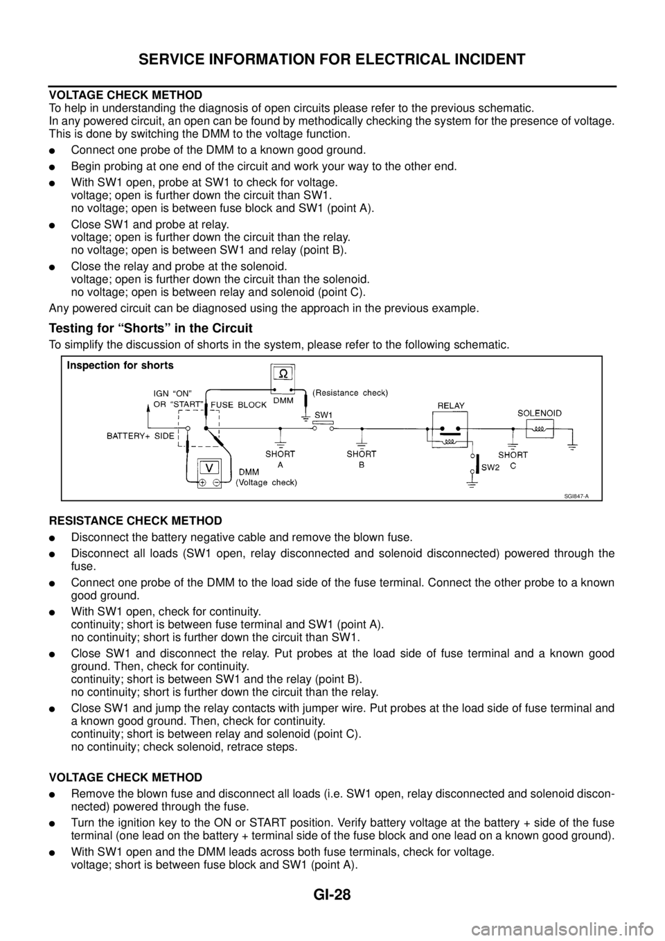
To simplify the discussion of shorts in the system, please refer to the following schematic.
RESISTANCE CHECK METHOD
lDisconnect the battery negative cable and remove the blown fuse.
lDisconnect all loads (SW1 open, relay disconnected and solenoid disconnected) powered through the
fuse.
lConnect one probe of the DMM to the load side of the fuse terminal. Connect the other probe to a known
good ground.
lWith SW1 open, check for continuity.
continuity; short is between fuse terminal and SW1 (point A).
no continuity; short is further down the circuit than SW1.
lClose SW1 and disconnect the relay. Put probes at the load side of fuse terminal and a known good
ground. Then, check for continuity.
continuity; short is between SW1 and the relay (point B).
no continuity; short is further down the circuit than the relay.
lClose SW1 and jump the relay contacts with jumper wire. Put probes at the load side of fuse terminal and
a known good ground. Then, check for continuity.
continuity; short is between relay and solenoid (point C).
no continuity; check solenoid, retrace steps.
VOLTAGE CHECK METHOD
lRemove the blown fuse and disconnect all loads (i.e. SW1 open, relay disconnected and solenoid discon-
nected) powered through the fuse.
lTurn the ignition key to the ON or START position. Verify battery voltage at the battery + side of the fuse
terminal (one lead on the battery + terminal side of the fuse block and one lead on a known good ground).
lWith SW1 open and the DMM leads across both fuse terminals, check for voltage.
voltage; short is between fuse block and SW1 (point A).
SGI847-A
Page 2838 of 3171
BATTERY
SC-5
C
D
E
F
G
H
I
J
L
MA
B
SC
BATTERYPFP:00011
How to Handle BatteryEKS00MZ7
CAUTION:
lIf it becomes necessary to start the engine with a booster battery and jumper cables, use a 12-volt
booster battery.
lAfter connecting battery cables, ensure that they are tightly clamped to battery terminals for good
contact.
lNever add distilled water through the hole used to check specific gravity.
METHODS OF PREVENTING OVER-DISCHARGE
The following precautions must be taken to prevent over-discharging a battery.
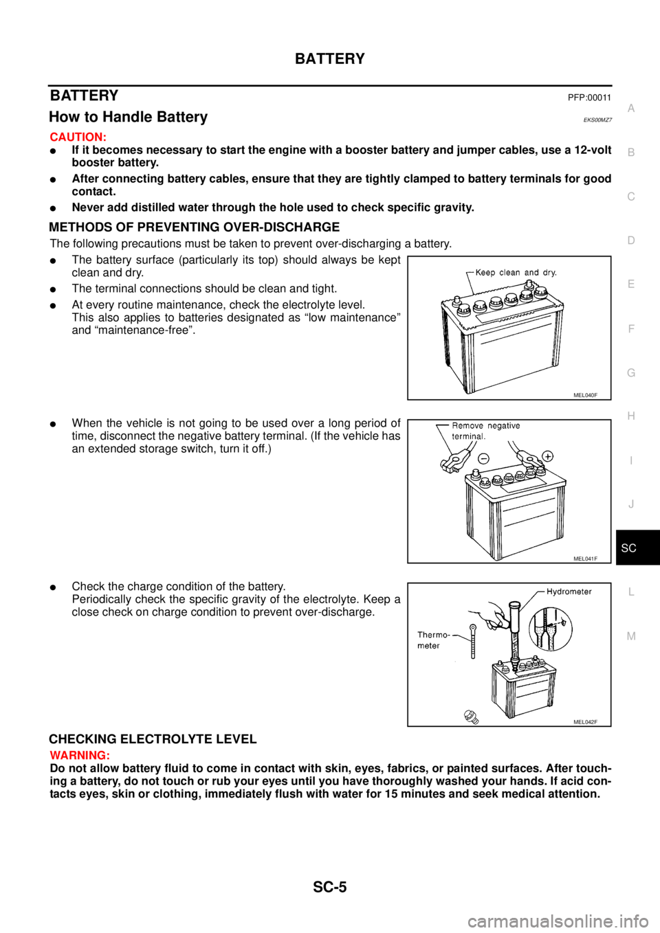
lThe battery surface (particularly its top) should always be kept
clean and dry.
lThe terminal connections should be clean and tight.
lAt every routine maintenance, check the electrolyte level.
This also applies to batteries designated as “low maintenance”
and “maintenance-free”.
lWhen the vehicle is not going to be used over a long period of
time, disconnect the negative battery terminal. (If the vehicle has
an extended storage switch, turn it off.)
lCheck the charge condition of the battery.
Periodically check the specific gravity of the electrolyte. Keep a
close check on charge condition to prevent over-discharge.
CHECKING ELECTROLYTE LEVEL
WARNING:
Do not allow battery fluid to come in contact with skin, eyes, fabrics, or painted surfaces. After touch-
ing a battery, do not touch or rub your eyes until you have thoroughly washed your hands. If acid con-
tacts eyes, skin or clothing, immediately flush with water for 15 minutes and seek medical attention.
MEL040F
MEL041F
MEL042F