2005 NISSAN NAVARA P1272
[x] Cancel search: P1272Page 984 of 3171

EC-4
Wiring Diagram .....................................................234
Diagnostic Procedure ...........................................235
DTC P1268 - P1271 FUEL INJECTOR ...................237
Component Description ........................................237
CONSULT-II Reference Value in Data Monitor Mode
.237
ECM Terminals and Reference Value ...................237
On Board Diagnosis Logic ....................................238
DTC Confirmation Procedure ...............................239
Wiring Diagram .....................................................240
Diagnostic Procedure ...........................................241
Component Inspection ..........................................243
Removal and Installation ......................................244
DTC P1272 FUEL PUMP ........................................245
Description ............................................................245
CONSULT-II Reference Value in Data Monitor Mode
.245
ECM Terminals and Reference Value ...................245
On Board Diagnosis Logic ....................................246
DTC Confirmation Procedure ...............................246
Wiring Diagram .....................................................248
Diagnostic Procedure ...........................................249
Component Inspection ..........................................250
Removal and Installation ......................................250
DTC P1273 FUEL PUMP ........................................251
Description ............................................................251
CONSULT-II Reference Value in Data Monitor Mode
.251
ECM Terminals and Reference Value ...................251
On Board Diagnosis Logic ....................................252
DTC Confirmation Procedure ...............................252
Wiring Diagram .....................................................254
Diagnostic Procedure ...........................................255
Component Inspection ..........................................257
Removal and Installation ......................................257
DTC P1274 FUEL PUMP ........................................258
Description ............................................................258
CONSULT-II Reference Value in Data Monitor Mode
.258
ECM Terminals and Reference Value ...................258
On Board Diagnosis Logic ....................................259
DTC Confirmation Procedure ...............................259
Wiring Diagram .....................................................260
Diagnostic Procedure ...........................................261
Component Inspection ..........................................262
Removal and Installation ......................................262
DTC P1275 FUEL PUMP ........................................263
Description ............................................................263
CONSULT-II Reference Value in Data Monitor Mode
.263
ECM Terminals and Reference Value ...................263
On Board Diagnosis Logic ....................................264
DTC Confirmation Procedure ...............................264
Wiring Diagram .....................................................266
Diagnostic Procedure ...........................................267
Component Inspection ..........................................268
Removal and Installation ......................................268
DTC P1616 ECM .....................................................269
Description ............................................................269On Board Diagnosis Logic ....................................269
DTC Confirmation Procedure ................................269
Diagnostic Procedure ............................................270
DTC P1622 INJECTOR ADJUSTMENT VALUE .....271
Description ............................................................271
On Board Diagnosis Logic ....................................271
DTC Confirmation Procedure ................................271
Diagnostic Procedure ............................................272
DTC P1623 INJECTOR ADJUSTMENT VALUE .....273
Description ............................................................273
On Board Diagnosis Logic ....................................273
DTC Confirmation Procedure ................................273
Diagnostic Procedure ............................................274
DTC P2135 APP SENSOR ......................................275
Description ............................................................275
CONSULT-II Reference Value in Data Monitor Mode
.275
ECM Terminals and Reference Value ...................275
On Board Diagnosis Logic ....................................276
DTC Confirmation Procedure ................................276
Wiring Diagram .....................................................277
Diagnostic Procedure ............................................278
Component Inspection ..........................................279
Removal and Installation .......................................280
DTC P2146, P2149 FUEL INJECTOR POWER SUP-
PLY ..........................................................................281
Component Description ........................................281
CONSULT-II Reference Value in Data Monitor Mode
.281
ECM Terminals and Reference Value ...................281
On Board Diagnosis Logic ....................................282
DTC Confirmation Procedure ................................283
Wiring Diagram .....................................................284
Diagnostic Procedure ............................................285
DTC P2147, P2148 FUEL INJECTOR CIRCUIT .....286
Component Description ........................................286
CONSULT-II Reference Value in Data Monitor Mode
.286
ECM Terminals and Reference Value ...................286
On Board Diagnosis Logic ....................................287
DTC Confirmation Procedure ................................288
Wiring Diagram .....................................................289
Diagnostic Procedure ............................................290
Component Inspection ..........................................292
Removal and Installation .......................................292
DTC P2228, P2229 BARO SENSOR ......................293
Description ............................................................293
On Board Diagnosis Logic ....................................293
DTC Confirmation Procedure ................................293
Diagnostic Procedure ............................................294
GLOW CONTROL SYSTEM ...................................295
Description ............................................................295
Wiring Diagram .....................................................296
Diagnostic Procedure ............................................297
Component Inspection ..........................................301
Removal and Installation .......................................301
EGR VOLUME CONTROL SYSTEM ......................302
Description ............................................................302
CONSULT-II Reference Value in Data Monitor Mode
Page 987 of 3171
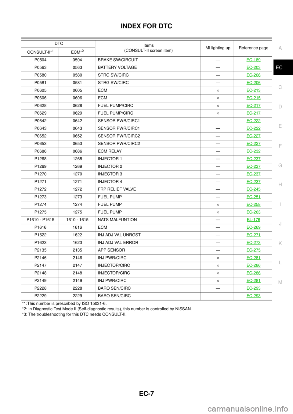
INDEX FOR DTC
EC-7
C
D
E
F
G
H
I
J
K
L
MA
EC
*1:This number is prescribed by ISO 15031-6.
*2: In Diagnostic Test Mode II (Self-diagnostic results), this number is controlled by NISSAN.
*3: The troubleshooting for this DTC needs CONSULT-II.P0504 0504 BRAKE SW/CIRCUIT —EC-189
P0563 0563 BATTERY VOLTAGE —EC-203
P0580 0580 STRG SW/CIRC —EC-206
P0581 0581 STRG SW/CIRC —EC-206
P0605 0605 ECM´EC-213
P0606 0606 ECM´EC-215
P0628 0628 FUEL PUMP/CIRC´EC-217
P0629 0629 FUEL PUMP/CIRC´EC-217
P0642 0642 SENSOR PWR/CIRC1 —EC-222
P0643 0643 SENSOR PWR/CIRC1 —EC-222
P0652 0652 SENSOR PWR/CIRC2 —EC-227
P0653 0653 SENSOR PWR/CIRC2 —EC-227
P0686 0686 ECM RELAY —EC-232
P1268 1268 INJECTOR 1 —EC-237
P1269 1269 INJECTOR 2 —EC-237
P1270 1270 INJECTOR 3 —EC-237
P1271 1271 INJECTOR 4 —EC-237
P1272 1272 FRP RELIEF VALVE —EC-245
P1273 1273 FUEL PUMP —EC-251
P1274 1274 FUEL PUMP´EC-258
P1275 1275 FUEL PUMP´EC-263
P1610 - P1615 1610 - 1615 NATS MALFUNTION —BL-176
P1616 1616 ECM —EC-269
P1622 1622 INJ ADJ VAL UNRGST —EC-271
P1623 1623 INJ ADJ VAL ERROR —EC-273
P2135 2135 APP SENSOR —EC-275
P2146 2146 INJ PWR/CIRC´EC-281
P2147 2147 INJECTOR/CIRC´EC-286
P2148 2148 INJECTOR/CIRC´EC-286
P2149 2149 INJ PWR/CIRC´EC-281
P2228 2228 BARO SEN/CIRC —EC-293
P2229 2229 BARO SEN/CIRC —EC-293
DTC
Items
(CONSULT-II screen item)MI lighting up Reference page
CONSULT-II*
1ECM*2
Page 988 of 3171
EC-8
INDEX FOR DTC
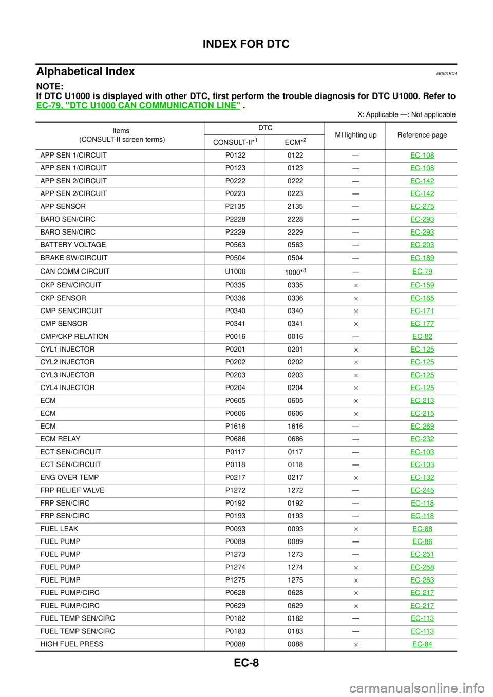
Alphabetical Index
EBS01KC4
NOTE:
If DTC U1000 is displayed with other DTC, first perform the trouble diagnosis for DTC U1000. Refer to
EC-79, "
DTC U1000 CAN COMMUNICATION LINE".
X: Applicable —: Not applicable
Items
(CONSULT-II screen terms)DTC
MI lighting up Reference page
CONSULT-II*
1ECM*2
APP SEN 1/CIRCUIT P0122 0122 —EC-108
APP SEN 1/CIRCUIT P0123 0123 —EC-108
APP SEN 2/CIRCUIT P0222 0222 —EC-142
APP SEN 2/CIRCUIT P0223 0223 —EC-142
APP SENSOR P2135 2135 —EC-275
BARO SEN/CIRC P2228 2228 —EC-293
BARO SEN/CIRC P2229 2229 —EC-293
BATTERY VOLTAGE P0563 0563 —EC-203
BRAKE SW/CIRCUIT P0504 0504 —EC-189
CAN COMM CIRCUIT U1000
1000*3—EC-79
CKP SEN/CIRCUIT P0335 0335´EC-159
CKP SENSOR P0336 0336´EC-165
CMP SEN/CIRCUIT P0340 0340´EC-171
CMP SENSOR P0341 0341´EC-177
CMP/CKP RELATION P0016 0016 —EC-82
CYL1 INJECTOR P0201 0201´EC-125
CYL2 INJECTOR P0202 0202´EC-125
CYL3 INJECTOR P0203 0203´EC-125
CYL4 INJECTOR P0204 0204´EC-125
ECM P0605 0605´EC-213
ECM P0606 0606´EC-215
ECM P1616 1616 —EC-269
ECM RELAY P0686 0686 —EC-232
ECT SEN/CIRCUIT P0117 0117 —EC-103
ECT SEN/CIRCUIT P0118 0118 —EC-103
ENG OVER TEMP P0217 0217´EC-132
FRP RELIEF VALVE P1272 1272 —EC-245
FRP SEN/CIRC P0192 0192 —EC-118
FRP SEN/CIRC P0193 0193 —EC-118
FUEL LEAK P0093 0093´EC-88
FUEL PUMP P0089 0089 —EC-86
FUEL PUMP P1273 1273 —EC-251
FUEL PUMP P1274 1274´EC-258
FUEL PUMP P1275 1275´EC-263
FUEL PUMP/CIRC P0628 0628´EC-217
FUEL PUMP/CIRC P0629 0629´EC-217
FUEL TEMP SEN/CIRC P0182 0182 —EC-113
FUEL TEMP SEN/CIRC P0183 0183 —EC-113
HIGH FUEL PRESS P0088 0088´EC-84
Page 1017 of 3171
TROUBLE DIAGNOSIS
EC-37
C
D
E
F
G
H
I
J
K
L
MA
EC
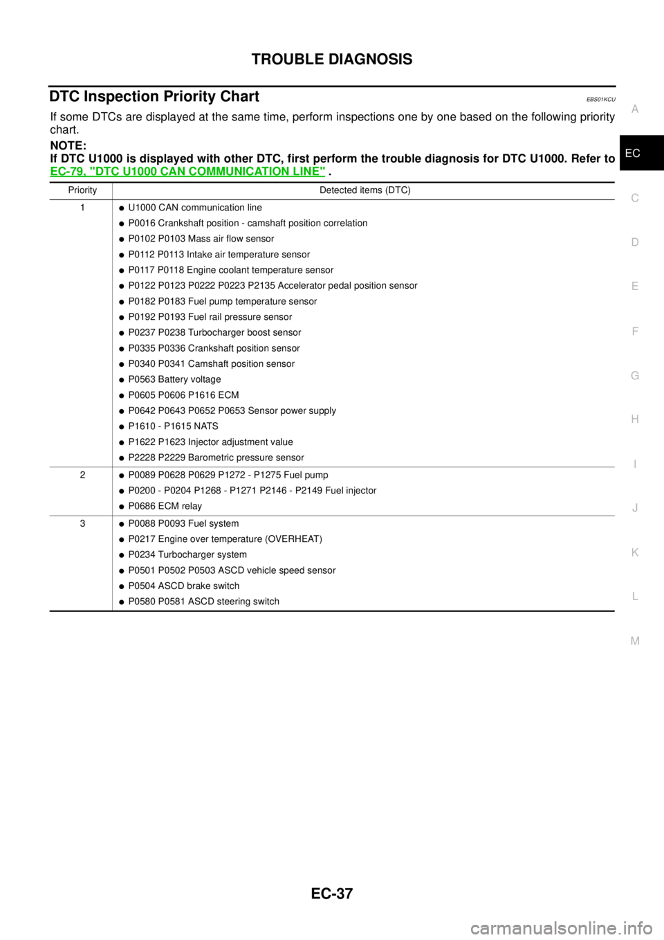
DTC Inspection Priority ChartEBS01KCU
If some DTCs are displayed at the same time, perform inspections one by one based on the following priority
chart.
NOTE:
If DTC U1000 is displayed with other DTC, first perform the trouble diagnosis for DTC U1000. Refer to
EC-79, "
DTC U1000 CAN COMMUNICATION LINE".
Priority Detected items (DTC)
1
lU1000 CAN communication line
lP0016 Crankshaft position - camshaft position correlation
lP0102 P0103 Mass air flow sensor
lP0112 P0113 Intake air temperature sensor
lP0117 P0118 Engine coolant temperature sensor
lP0122 P0123 P0222 P0223 P2135 Accelerator pedal position sensor
lP0182 P0183 Fuel pump temperature sensor
lP0192 P0193 Fuel rail pressure sensor
lP0237 P0238 Turbocharger boost sensor
lP0335 P0336 Crankshaft position sensor
lP0340 P0341 Camshaft position sensor
lP0563 Battery voltage
lP0605 P0606 P1616 ECM
lP0642 P0643 P0652 P0653 Sensor power supply
lP1610 - P1615 NATS
lP1622 P1623 Injector adjustment value
lP2228 P2229 Barometric pressure sensor
2
lP0089 P0628 P0629 P1272 - P1275 Fuel pump
lP0200 - P0204 P1268 - P1271 P2146 - P2149 Fuel injector
lP0686 ECM relay
3
lP0088 P0093 Fuel system
lP0217 Engine over temperature (OVERHEAT)
lP0234 Turbocharger system
lP0501 P0502 P0503 ASCD vehicle speed sensor
lP0504 ASCD brake switch
lP0580 P0581 ASCD steering switch
Page 1225 of 3171
DTC P1272 FUEL PUMP
EC-245
C
D
E
F
G
H
I
J
K
L
MA
EC
DTC P1272 FUEL PUMPPFP:16700
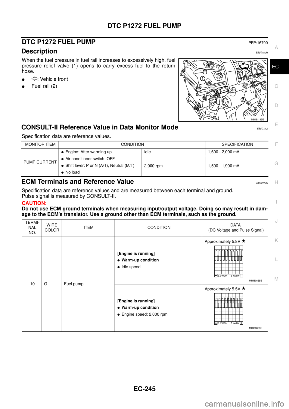
DescriptionEBS01KJH
When the fuel pressure in fuel rail increases to excessively high, fuel
pressure relief valve (1) opens to carry excess fuel to the return
hose.
l: Vehicle front
lFuel rail (2)
CONSULT-II Reference Value in Data Monitor ModeEBS01KJI
Specification data are reference values.
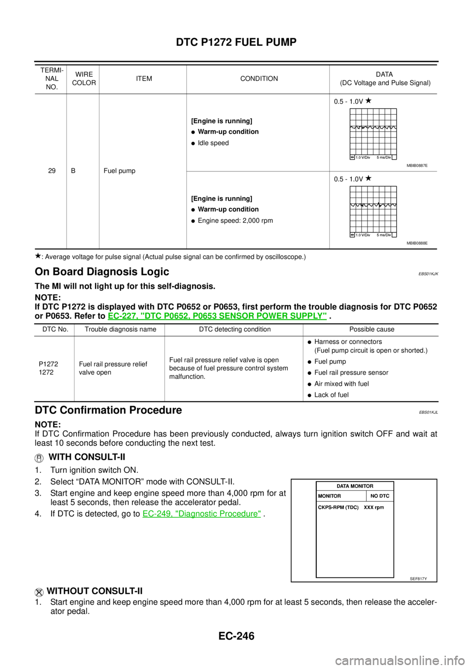
ECM Terminals and Reference ValueEBS01KJJ
Specification data are reference values and are measured between each terminal and ground.
Pulse signal is measured by CONSULT-II.
CAUTION:
Do not use ECM ground terminals when measuring input/output voltage. Doing so may result in dam-
age to the ECM's transistor. Use a ground other than ECM terminals, such as the ground.
MBIB1199E
MONITOR ITEM CONDITION SPECIFICATION
PUMP CURRENT
lEngine: After warming up
lAir conditioner switch: OFF
lShift lever: P or N (A/T), Neutral (M/T)
lNo loadIdle 1,600 - 2,000 mA
2,000 rpm 1,500 - 1,900 mA
TERMI-
NAL
NO.WIRE
COLORITEM CONDITIONDATA
(DC Voltage and Pulse Signal)
10 G Fuel pump[Engine is running]
lWarm-up condition
lIdle speedApproximately 5.8V
[Engine is running]
lWarm-up condition
lEngine speed: 2,000 rpmApproximately 5.5V
MBIB0885E
MBIB0886E
Page 1226 of 3171
EC-246
DTC P1272 FUEL PUMP
: Average voltage for pulse signal (Actual pulse signal can be confirmed by oscilloscope.)
On Board Diagnosis LogicEBS01KJK
The MI will not light up for this self-diagnosis.
NOTE:
If DTC P1272 is displayed with DTC P0652 or P0653, first perform the trouble diagnosis for DTC P0652
or P0653. Refer toEC-227, "
DTC P0652, P0653 SENSOR POWER SUPPLY".
DTC Confirmation ProcedureEBS01KJL
NOTE:
If DTC Confirmation Procedure has been previously conducted, always turn ignition switch OFF and wait at
least 10 seconds before conducting the next test.
WITH CONSULT-II
1. Turn ignition switch ON.
2. Select “DATA MONITOR” mode with CONSULT-II.
3. Start engine and keep engine speed more than 4,000 rpm for at
least 5 seconds, then release the accelerator pedal.
4. If DTC is detected, go toEC-249, "
Diagnostic Procedure".
WITHOUT CONSULT-II
1. Start engine and keep engine speed more than 4,000 rpm for at least 5 seconds, then release the acceler-
ator pedal.
29 B Fuel pump[Engine is running]
lWarm-up condition
lIdle speed0.5 - 1.0V
[Engine is running]
lWarm-up condition
lEngine speed: 2,000 rpm0.5 - 1.0V TERMI-
NAL
NO.WIRE
COLORITEM CONDITIONDATA
(DC Voltage and Pulse Signal)
MBIB0887E
MBIB0888E
DTC No. Trouble diagnosis name DTC detecting condition Possible cause
P1272
1272Fuel rail pressure relief
valve openFuel rail pressure relief valve is open
because of fuel pressure control system
malfunction.
lHarness or connectors
(Fuel pump circuit is open or shorted.)
lFuel pump
lFuel rail pressure sensor
lAir mixed with fuel
lLack of fuel
SEF817Y
Page 1227 of 3171
DTC P1272 FUEL PUMP
EC-247
C
D
E
F
G
H
I
J
K
L
MA
EC
2. Turn ignition switch OFF, wait at least 10 seconds and then turn ON.
3. Perform Diagnostic Test Mode II (Self-diagnostic results) with ECM.
4. If DTC is detected, go toEC-249, "
Diagnostic Procedure".
Page 1228 of 3171
EC-248
DTC P1272 FUEL PUMP
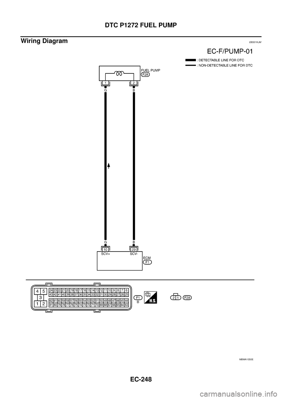
Wiring Diagram
EBS01KJM
MBWA1050E