2005 NISSAN NAVARA tyre pressure
[x] Cancel search: tyre pressurePage 790 of 3171

BR-4
PREPARATION
PREPARATION
PFP:00002
Special Service ToolsEFS005SE
Commercial Service ToolsEFS005TE
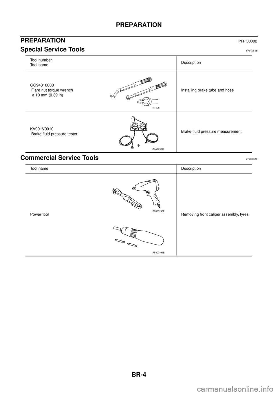
Tool number
Tool nameDescription
GG94310000
Flare nut torque wrench
a:10 mm (0.39 in)Installing brake tube and hose
KV991V0010
Brake fluid pressure testerBrake fluid pressure measurement
NT406
ZZA0752D
Tool nameDescription
Power toolRemoving front caliper assembly, tyres
PBIC0190E
PBIC0191E
Page 802 of 3171

BR-16
LOAD SENSING VALVE
Inspection
EFS006A8
INSPECTION
1. With the vehicle in unladen condition, a person should sit in driver's seat at the rear. Then he/she should
get out of car gently. (This is to stabilize suspension deflection.)
NOTE:
“Unladen condition”: with full coolant, lubricant, 6 to 8 litters of fuel, spare tyre, jack, and hand tools
loaded.
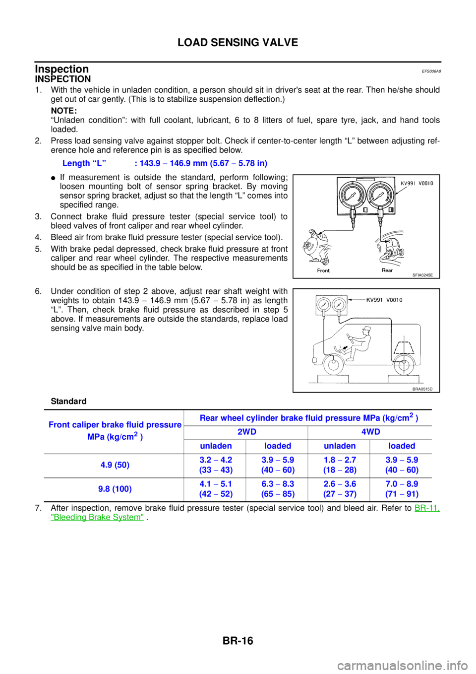
2. Press load sensing valve against stopper bolt. Check if center-to-center length “L” between adjusting ref-
erence hole and reference pin is as specified below.
lIf measurement is outside the standard, perform following;
loosen mounting bolt of sensor spring bracket. By moving
sensor spring bracket, adjust so that the length “L” comes into
specified range.
3. Connect brake fluid pressure tester (special service tool) to
bleed valves of front caliper and rear wheel cylinder.
4. Bleed air from brake fluid pressure tester (special service tool).
5. With brake pedal depressed, check brake fluid pressure at front
caliper and rear wheel cylinder. The respective measurements
should be as specified in the table below.
6. Under condition of step 2 above, adjust rear shaft weight with
weights to obtain 143.9-146.9 mm (5.67-5.78 in) as length
“L”. Then, check brake fluid pressure as described in step 5
above. If measurements are outside the standards, replace load
sensing valve main body.
Standard
7. After inspection, remove brake fluid pressure tester (special service tool) and bleed air. Refer toBR-11,
"Bleeding Brake System". Length “L” : 143.9-146.9 mm (5.67-5.78 in)
SFIA0245E
BRA0515D
Front caliper brake fluid pressure
MPa (kg/cm
2)Rear wheel cylinder brake fluid pressure MPa (kg/cm
2)
2WD 4WD
unladen loaded unladen loaded
4.9 (50)3.2-4.2
(33-43)3.9-5.9
(40-60)1.8-2.7
(18-28)3.9-5.9
(40-60)
9.8 (100)4.1-5.1
(42-52)6.3-8.3
(65-85)2.6-3.6
(27-37)7.0-8.9
(71-91)
Page 827 of 3171
![NISSAN NAVARA 2005 Repair Workshop Manual SYSTEM DESCRIPTION
BRC-5
[ABS]
C
D
E
G
H
I
J
K
L
MA
B
BRC
SYSTEM DESCRIPTIONPFP:00000
System DiagramEFS005TJ
FunctionsEFS005TK
ABS
lThe Anti-Lock Brake System is a function that detects wheel revoluti NISSAN NAVARA 2005 Repair Workshop Manual SYSTEM DESCRIPTION
BRC-5
[ABS]
C
D
E
G
H
I
J
K
L
MA
B
BRC
SYSTEM DESCRIPTIONPFP:00000
System DiagramEFS005TJ
FunctionsEFS005TK
ABS
lThe Anti-Lock Brake System is a function that detects wheel revoluti](/manual-img/5/57362/w960_57362-826.png)
SYSTEM DESCRIPTION
BRC-5
[ABS]
C
D
E
G
H
I
J
K
L
MA
B
BRC
SYSTEM DESCRIPTIONPFP:00000
System DiagramEFS005TJ
FunctionsEFS005TK
ABS
lThe Anti-Lock Brake System is a function that detects wheel revolution while braking, and it improves
handling stability during sudden braking by electrically preventing 4 wheels lock. Maneuverability is also
improved for avoiding obstacles.
lElectrical system diagnosis by CONSULT-II is available.
EBD
lElectronic Brake Distributor is a function that detects subtle slippages between the front and rear tyre dur-
ing braking, and it improves handling stability by electrically controlling the brake fluid pressure which
results in reduced rear tyre slippage.
lElectrical system diagnosis by CONSULT-II is available.
Operation That Is Not “System Error”EFS005TL
ABS
lWhen starting engine or just after starting vehicle, brake pedal may vibrate or the motor operating noise
may be heard from engine room. This is a normal states of the operation check.
lDuring ABS operation, brake pedal lightly vibrates and a mechanical noise may be heard. This is normal.
lStopping distance may be longer than that of vehicles without ABS when vehicle drives on rough, gravel,
or snow-covered (fresh, deep snow) roads.
Fail-Safe FunctionEFS005TM
ABS, EBD SYSTEM
In case of electrical malfunction with ABS, ABS warning lamp will turn on. In case of electrical incidents with
EBD, brake warning lamp and ABS warning lamp will turn on. Simultaneously, ABS become one of following
conditions of Fail-Safe function.
1. For ABS malfunction, only EBD is activated and condition of vehicle is same condition of vehicles without
ABS system.
NOTE:
ABS self-diagnosis sound may be heard.That is a normal condition because a self-diagnosis for “Ignition
switch ON” and “The first starting” are being performed.
2. For EBD malfunction, EBD and ABS become inoperative, and condition of vehicle is same as condition of
vehicles without ABS, EBD system.
SFIA3001E
Page 843 of 3171
![NISSAN NAVARA 2005 Repair Workshop Manual TROUBLE DIAGNOSIS
BRC-21
[ABS]
C
D
E
G
H
I
J
K
L
MA
B
BRC
Note 1:Confirm tyre pressure is normal.
Note 2:On and off timing for warning lamp and indicator lamp. Refer toBRC-24, "
BASIC INSPECTION 3 ABS NISSAN NAVARA 2005 Repair Workshop Manual TROUBLE DIAGNOSIS
BRC-21
[ABS]
C
D
E
G
H
I
J
K
L
MA
B
BRC
Note 1:Confirm tyre pressure is normal.
Note 2:On and off timing for warning lamp and indicator lamp. Refer toBRC-24, "
BASIC INSPECTION 3 ABS](/manual-img/5/57362/w960_57362-842.png)
TROUBLE DIAGNOSIS
BRC-21
[ABS]
C
D
E
G
H
I
J
K
L
MA
B
BRC
Note 1:Confirm tyre pressure is normal.
Note 2:On and off timing for warning lamp and indicator lamp. Refer toBRC-24, "
BASIC INSPECTION 3 ABS WARNING LAMP AND
BRAKE WARNING LAMP INSPECTION".
Active TestEFS005TW
CAUTION:
lDo not perform active test while driving vehicle.
lMake sure to completely bleed air from brake system.
lActive test cannot be performed when ABS warning lamp is on.
lABS and brake warming lamps turn on during active test.
OPERATION PROCEDURE
1. Touch START (NISSAN BASED VHCL), “ABS”, “ACTIVE TEST” in order on CONSULT-II screen.
If “ABS” is not indicated, go toGI-50, "
CONSULT-II Data Link Connector (DLC) Circuit".
CAUTION:
When “START (NISSAN BASED VHCL)” is touched immediately after starting engine or turning on
ignition switch, “ABS” might not be displayed in the “SELECT SYSTEM” screen. In this case,
repeat the operation from step 1.
2. Touch “SELECT TEST ITEM” is displayed.
3. Touch necessary test item.
4. While “MAIN SIGNALS” indication is inverted, touch “START”.
5. “ACTIVE TEST” screen will be displayed so perform the following test.
lSolenoid valve
lABS motor
NOTE:
lWhen active test is performed while depressing the pedal, the pedal depression amount will
change.This is normal.
l“TEST IS STOPPED” is displayed 10 seconds after operation start.
lAfter “TEST IS STOPPED” is displayed, to perform test again, touch “BACK” and repeat step 3.
S ABS SIGNAL ABS operationABS active ON
ABS not active OFF
SEBD FAIL SIG
ABS FAIL SIGSystem error signal statusMalfunctions condition
(When system is malfunc-
tioning)OFF
S CRANKING SIG CRANKING statusCranking ON
Not cranking OFF E:ECU INPUT SIGNALS M:MAIN SIGNALS S:SELECTION FROM MENU
SELECT
MONITOR
ITEMMonitor item Display contentData monitor
ConditionReference value in
normal operation
SFIA1802E
Page 846 of 3171
![NISSAN NAVARA 2005 Repair Workshop Manual BRC-24
[ABS]
TROUBLE DIAGNOSIS
BASIC INSPECTION 3 ABS WARNING LAMP AND BRAKE WARNING LAMP INSPECTION
ON and OFF Timing for ABS Warning Lamp, Brake Warning Lamp
´:ON –:OFF
Note 1:Brake warning lamp NISSAN NAVARA 2005 Repair Workshop Manual BRC-24
[ABS]
TROUBLE DIAGNOSIS
BASIC INSPECTION 3 ABS WARNING LAMP AND BRAKE WARNING LAMP INSPECTION
ON and OFF Timing for ABS Warning Lamp, Brake Warning Lamp
´:ON –:OFF
Note 1:Brake warning lamp](/manual-img/5/57362/w960_57362-845.png)
BRC-24
[ABS]
TROUBLE DIAGNOSIS
BASIC INSPECTION 3 ABS WARNING LAMP AND BRAKE WARNING LAMP INSPECTION
ON and OFF Timing for ABS Warning Lamp, Brake Warning Lamp
´:ON –:OFF
Note 1:Brake warning lamp will turn on in case of operating parking brake (switch turned on) or of a actuating brake fluid level switch
(brake fluid is insufficient).
Note 2:After starting engine, turn OFF.
Check the following items when unsuitable for an above condition.
lABS warning lamp: Refer toBRC-28, "Inspection 4 CAN Communication Circuit".
lBrake waning lamp: Refer toBRC-28, "Inspection 4 CAN Communication Circuit",BRC-30, "Inspection 6
Brake Fluid Level Switch Circuit",BRC-32, "Inspection 7 Parking Brake Switch Circuit".
If malfunction is not found, refer toBRC-33, "
Inspection 8 Warning lamp system".
Inspection 1 Wheel Sensor SystemEFS005TZ
Check each part according to CONSULT-II self-diagnostic results, and then identify the parts to be replaced.
CAUTION:
Check each part between wheel sensor terminals.
INSPECTION PROCEDURE
1.CHECK SELF-DIAGNOSTIC RESULTS
Check self-diagnostic results.
Is above displayed in self-diagnosis display items?
YES >> GO TO 2.
NO >> INSPECTION END
2.CHECK TYRE
Check air pressure, wear and size.
Are air pressure, wear and size within standard values?
YES >> GO TO 3.
NO >> Adjust air pressure, or replace tyre.
Condition ABS warning lampBrake warning lamp
[Note 1]Remarks
Ignition SW OFF – — —
Approx. 2 seconds after ignition
switch is turned ON´´[Note 2] —
Approx. 2 seconds later after ignition
switch ON–´[Note 2]Go out 2 seconds after ignition
switch is turned ON.
ABS error´—There is an ABS actuator and
electric unit (control unit) error.
(Power, ground or system mal-
function)
EBD error´´—
Self-diagnostic results
FR RH SENSOR-1,-2
FR LH SENSOR- 1,-2
RR RH SENSOR-1,-2
RR LH SENSOR-1,- 2
ABS SENSOR [MALFUNCTION SIGNAL]
Page 2280 of 3171

DESCRIPTION
MA-5
C
D
E
F
G
H
I
J
K
MA
B
MA
DESCRIPTIONPFP:00000
Pre-Delivery Inspection ItemsELS001K2
Shown below are Pre-delivery Inspection Items required for the new vehicle. It is recommended that
necessary items other than those listed here be added, paying due regard to the conditions in each
country.
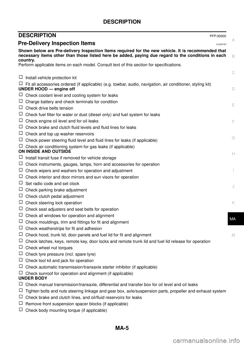
Perform applicable items on each model. Consult text of this section for specifications.
Install vehicle protection kit
Fit all accessories ordered (if applicable) (e.g. towbar, audio, navigation, air conditioner, styling kit)
UNDER HOOD — engine off
Check coolant level and cooling system for leaks
Charge battery and check terminals for condition
Check drive belts tension
Check fuel filter for water or dust (diesel only) and fuel system for leaks
Check engine oil level and for oil leaks
Check brake and clutch fluid levels and fluid lines for leaks
Check and top up washer reservoirs
Check power steering fluid level and fluid lines for leaks (if applicable)
Check air conditioning system for gas leaks (if applicable)
ON INSIDE AND OUTSIDE
Install transit fuse if removed for vehicle storage
Check instruments, gauges, lamps, horn and accessories for operation
Check wipers and washers for operation and adjustment
Check interior and door mirrors and sun visors for operation
Set radio code and set clock
Check parking brake adjustment
Check clutch pedal adjustment
Check steering lock operation
Check seat adjusters and seat belts for operation
Check all windows for operation and alignment
Check mouldings, trim and fittings for fit and alignment
Check weatherstrips for fit and adhesion
Check hood, trunk lid, door panels and fuel lid for fit and alignment
Check latches, keys, remote key, door locks and remote trunk lid and fuel lid release for operation
Check wheel nut torques
Check tyre pressure (incl. spare tyre)
Check tool kit and jack for operation
Check automatic transmission/transaxle starter inhibitor (if applicable)
Check sunroof for operation and alignment (if applicable)
UNDER BODY
Check manual transmission/transaxle, differential and transfer box for oil level and oil leaks
Tighten bolts and nuts steering linkage and gear box, axle/suspension parts, propeller and exhaust system
Check brake and clutch lines, and oil/fluid reservoirs for leaks
Remove front suspension spacer blocks (if applicable)
Check body mounting torque (if applicable)
Page 2642 of 3171

POWER STEERING GEAR AND LINKAGE
PS-15
C
D
E
F
H
I
J
K
L
MA
B
PS
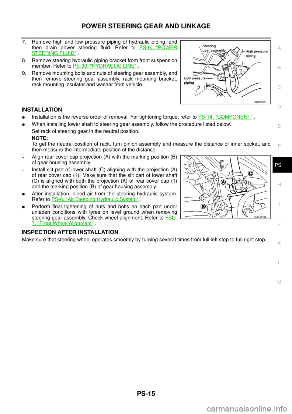
7. Remove high and low pressure piping of hydraulic piping, and
then drain power steering fluid. Refer toPS-6, "
POWER
STEERING FLUID".
8. Remove steering hydraulic piping bracket from front suspension
member. Refer toPS-30, "
HYDRAULIC LINE".
9. Remove mounting bolts and nuts of steering gear assembly, and
then remove steering gear assembly, rack mounting bracket,
rack mounting insulator and washer from vehicle.
INSTALLATION
lInstallation is the reverse order of removal. For tightening torque, refer toPS-14, "COMPONENT".
lWhen installing lower shaft to steering gear assembly, follow the procedure listed below.
–Set rack of steering gear in the neutral position.
NOTE:
To get the neutral position of rack, turn pinion assembly and measure the distance of inner socket, and
then measure the intermediate position of the distance.
–Align rear cover cap projection (A) with the marking position (B)
of gear housing assembly.
–Install slit part of lower shaft (C) aligning with the projection (A)
of rear cover cap (1). Make sure that the slit part of lower shaft
(C) is aligned with both the projection (A) of rear cover cap (1)
and the marking position (B) of gear housing assembly.
lAfter installation, bleed air from the steering hydraulic system.
Refer toPS-6, "
Air Bleeding Hydraulic System".
lPerform final tightening of nuts and bolts on each part under
unladen conditions with tyres on level ground when removing
steering gear assembly. Check wheel alignment. Refer toFSU-
7, "Front Wheel Alignment".
INSPECTION AFTER INSTALLATION
Make sure that steering wheel operates smoothly by turning several times from full left stop to full right stop.
LGIA0032E
SGIA1140E