2005 NISSAN NAVARA cruise control
[x] Cancel search: cruise controlPage 1 of 3171
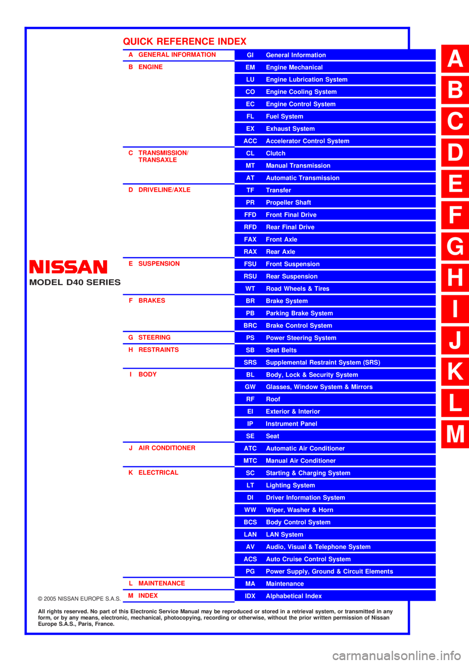
MODELD40 SERIES
2005 NISSAN EUROPE S.A.S.
All rights reserved. No part of this Electronic Service Manual may be reproduced or stored in a retrieval system, or transmitted in any
form, or by any means, electronic, mechanical, photocopying, recording or otherwise, without the prior written permission of Nissan
Europe S.A.S., Paris, France.
A GENERAL INFORMATION
B ENGINE
C TRANSMISSION/TRANSAXLE
D DRIVELINE/AXLE
E SUSPENSION F BRAKES
G STEERING H RESTRAINTS
I BODY
J AIR CONDITIONER
K ELECTRICAL
L MAINTENANCE
M INDEXGI General Information
EM Engine Mechanical
LU Engine Lubrication System
CO Engine Cooling System
EC Engine Control System
FL Fuel System
EX Exhaust System
ACC Accelerator Control System
CL Clutch
MTManualTransmission
AT Automatic Transmission
TF Transfer
PR Propeller Shaft
FFD Front Final Drive
RFD Rear Final Drive
FAX Front Axle
RAX Rear Axle
FSU Front Suspension
RSU Rear Suspension
WT Road Wheels & Tires
BR Brake System
PB Parking Brake System
BRC Brake Control System
PS Power Steering System
SB Seat Belts
SRS Supplemental Restraint System (SRS)
BL Body, Lock & Security System
GW Glasses, Window System & Mirrors
RF Roof
EI Exterior & Interior
IP Instrument Panel
SE Seat
ATC Automatic Air Conditioner
MTC Manual Air Conditioner
SC Starting & Charging System
LT Lighting System
DI Driver Information System
WW Wiper, Washer & Horn
BCS Body Control System
LAN LAN System
AV Audio, Visual & Telephone System
ACS Auto Cruise Control System
PG Power Supply, Ground & Circuit Elements
MA Maintenance
IDX Alphabetical Index
QUICK REFERENCE INDEX
A
B
C
D
E
F
G
H
I
J
K
L
M
Page 7 of 3171

ACS-1
AUTO CRUISE CONTROL SYSTEM
K ELECTRICAL
CONTENTS
C
D
E
F
G
H
I
J
L
M
SECTIONACS
A
B
ACS
AUTO CRUISE CONTROL SYSTEM
ASCD
AUTOMATIC SPEED CONTROL DEVICE (ASCD)..... 2
Description ............................................................... 2
Page 9 of 3171
AT-1
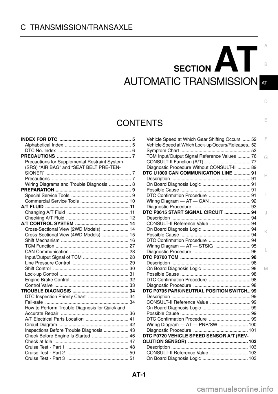
AUTOMATIC TRANSMISSION
C TRANSMISSION/TRANSAXLE
CONTENTS
D
E
F
G
H
I
J
K
L
M
SECTIONAT
A
B
AT
AUTOMATIC TRANSMISSION
INDEX FOR DTC ........................................................ 5
Alphabetical Index .................................................... 5
DTC No. Index ......................................................... 6
PRECAUTIONS .......................................................... 7
Precautions for Supplemental Restraint System
(SRS)“AIRBAG”and“SEATBELTPRE-TEN-
SIONER” .................................................................. 7
Precautions .............................................................. 7
Wiring Diagrams and Trouble Diagnosis .................. 8
PREPARATION ........................................................... 9
Special Service Tools ............................................... 9
Commercial Service Tools ...................................... 10
A/T FLUID ..................................................................11
Changing A/T Fluid ................................................. 11
Checking A/T Fluid ................................................. 12
A/T CONTROL SYSTEM .......................................... 14
Cross-Sectional View (2WD Models) ..................... 14
Cross-Sectional View (4WD Models) ..................... 15
Shift Mechanism ..................................................... 16
TCM Function ......................................................... 27
CAN Communication .............................................. 28
Input/Output Signal of TCM .................................... 28
Line Pressure Control ............................................ 29
Shift Control ........................................................... 30
Lock-up Control ...................................................... 31
Engine Brake Control ............................................. 32
Control Valve .......................................................... 33
TROUBLE DIAGNOSIS ............................................ 34
DTC Inspection Priority Chart ................................ 34
Fail-safe ................................................................. 34
How to Perform Trouble Diagnosis for Quick and
Accurate Repair ..................................................... 36
A/T Electrical Parts Location .................................. 41
Circuit Diagram ...................................................... 42
Inspections Before Trouble Diagnosis .................... 43
Check Before Engine Is Started ............................. 46
Check at Idle .......................................................... 47
Cruise Test - Part 1 ................................................ 48
Cruise Test - Part 2 ................................................ 50
Cruise Test - Part 3 ................................................ 51Vehicle Speed at Which Gear Shifting Occurs ....... 52
Vehicle Speed at Which Lock-up Occurs/Releases... 52
Symptom Chart ....................................................... 53
TCM Input/Output Signal Reference Values ........... 76
CONSULT-II Function (A/T) .................................... 77
Diagnostic Procedure Without CONSULT-II ........... 89
DTC U1000 CAN COMMUNICATION LINE .............. 91
Description .............................................................. 91
On Board Diagnosis Logic ...................................... 91
Possible Cause ....................................................... 91
DTC Confirmation Procedure ................................. 91
Wiring Diagram — AT — CAN ................................ 92
Diagnostic Procedure ............................................. 93
DTC P0615 START SIGNAL CIRCUIT ..................... 94
Description .............................................................. 94
CONSULT-II Reference Value ................................ 94
On Board Diagnosis Logic ...................................... 94
Possible Cause ....................................................... 94
DTC Confirmation Procedure ................................. 94
Wiring Diagram — AT — STSIG ............................ 95
Diagnostic Procedure ............................................. 96
DTC P0700 TCM ....................................................... 98
Description .............................................................. 98
On Board Diagnosis Logic ...................................... 98
Possible Cause ....................................................... 98
DTC Confirmation Procedure ................................. 98
Diagnostic Procedure ............................................. 98
DTC P0705 PARK/NEUTRAL POSITION SWITCH... 99
Description .............................................................. 99
CONSULT-II Reference Value ................................ 99
On Board Diagnosis Logic ...................................... 99
Possible Cause ....................................................... 99
DTC Confirmation Procedure ................................. 99
Wiring Diagram — AT — PNP/SW .......................100
Diagnostic Procedure ...........................................101
DTC P0720 VEHICLE SPEED SENSOR A/T (REV-
OLUTION SENSOR) ...............................................103
Description ............................................................103
CONSULT-II Reference Value ..............................103
On Board Diagnosis Logic ....................................103
Page 59 of 3171

TROUBLE DIAGNOSIS
AT-51
D
E
F
G
H
I
J
K
L
MA
B
AT
4.CHECK SHIFT-UP D3®D4AND ENGINE BRAKE
When the A/T changes speed D
3®D4, return accelerator pedal.
With CONSULT-II
Read the gear position. Refer toAT-83, "
DATA MONITOR MODE".
Does the A/T shift-up D
3®D4and apply the engine brake?
YES >> 1. Stop the vehicle.
2. Go toAT-51, "
Cruise Test - Part 3".
NO >> Enter a check mark at “A/T Does Not Shift: D
3®D4”onAT-38, "DIAGNOSTIC WORKSHEET",
then continue the road test. Go toAT-51, "
Cruise Test - Part 3".
Cruise Test - Part 3ECS00FX5
1.CHECK SHIFT-DOWN
1. Confirm overdrive control switch is ON position.
2. Confirm gear selector lever is in “D” position.
3. Accelerate vehicle using half-throttle to D
5.
4. Release accelerator pedal.
5. Set overdrive control switch to OFF position while driving in D
5.
With CONSULT-II
Read the gear position. Refer toAT-83, "
DATA MONITOR MODE".
Does A/T shift from D
5to D4(OD OFF)?
YES >> GO TO 2.
NO >> Enter a check mark at “A/T does not shift: 5th gear®4th gear” on theAT-38, "
DIAGNOSTIC
WORKSHEET", then continue the road test.
2.CHECK SHIFT-DOWN
During D
4driving, is downshift from “D”®“3”®“2”®“1” performed?
With CONSULT-II
Read the gear position. Refer toAT-83, "
DATA MONITOR MODE".
Is downshifting correctly performed?
YES >> GO TO 3.
NO >> Enter a check mark at “A/T does not shift” at the corresponding position (4th®3rd, 3rd®2nd,
2nd®1st) on theAT-38, "
DIAGNOSTIC WORKSHEET", then continue the road test.
3.CHECK ENGINE BRAKE
Check engine brake.
Does engine braking effectively reduce speed in 1
1position?
YES >> 1. Stop the vehicle.
2. Perform self-diagnosis. Refer toAT-80, "
SELF-DIAGNOSTIC RESULT MODE",AT-89, "Diag-
nostic Procedure Without CONSULT-II".
NO >> Enter a check mark at “Vehicle Does Not Decelerate by Engine Brake” on theAT-38, "
DIAGNOS-
TIC WORKSHEET", then continue trouble diagnosis.
Page 92 of 3171
AT-84
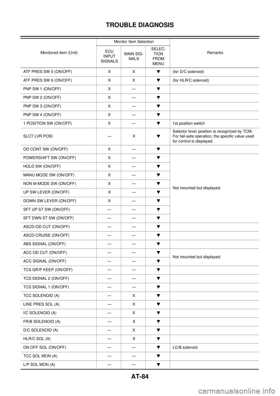
TROUBLE DIAGNOSIS
ATF PRES SW 5 (ON/OFF) X X (for D/C solenoid)
ATF PRES SW 6 (ON/OFF) X X (for HLR/C solenoid)
PNP SW 1 (ON/OFF) X —
PNP SW 2 (ON/OFF) X —
PNP SW 3 (ON/OFF) X —
PNP SW 4 (ON/OFF) X —
1 POSITION SW (ON/OFF) X — 1st position switch
SLCT LVR POSI — XSelector lever position is recognized by TCM.
For fail-safe operation, the specific value used
for control is displayed.
OD CONT SW (ON/OFF) X —
POWERSHIFT SW (ON/OFF) X —
Not mounted but displayed. HOLD SW (ON/OFF) X —
MANU MODE SW (ON/OFF) X —
NON M-MODE SW (ON/OFF) X —
UP SW LEVER (ON/OFF) X —
DOWN SW LEVER (ON/OFF) X —
SFTUPSTSW(ON/OFF) — —
SFT DWN ST SW (ON/OFF) — —
ASCD-OD CUT (ON/OFF) — —
ASCD-CRUISE (ON/OFF) — —
ABS SIGNAL (ON/OFF) — —
ACC OD CUT (ON/OFF) — —
Not mounted but displayed.
ACC SIGNAL (ON/OFF) — —
TCS GR/P KEEP (ON/OFF) — —
TCS SIGNAL 2 (ON/OFF) — —
TCS SIGNAL 1 (ON/OFF) — —
TCC SOLENOID (A) — X
LINE PRES SOL (A) — X
I/C SOLENOID (A) — X
FR/B SOLENOID (A) — X
D/C SOLENOID (A) — X
HLR/C SOL (A) — X
ON OFF SOL (ON/OFF) — — LC/B solenoid
TCC SOL MON (A) — —
L/P SOL MON (A) — —Monitored item (Unit)Monitor Item Selection
Remarks ECU
INPUT
SIGNALSMAIN SIG-
NALSSELEC-
TION
FROM
MENU
Page 195 of 3171
TROUBLE DIAGNOSIS FOR SYMPTOMS
AT-187
D
E
F
G
H
I
J
K
L
MA
B
AT
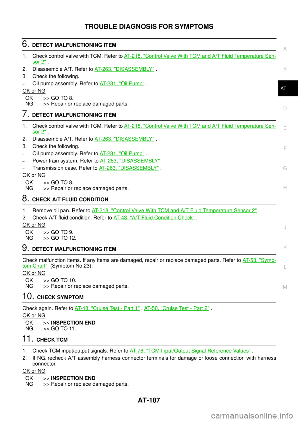
6.DETECT MALFUNCTIONING ITEM
1. Check control valve with TCM. Refer toAT- 2 1 8 , "
Control Valve With TCM and A/T Fluid Temperature Sen-
sor 2".
2. Disassemble A/T. Refer toAT- 2 6 3 , "
DISASSEMBLY".
3. Check the following.
–Oil pump assembly. Refer toAT- 2 8 1 , "Oil Pump".
OK or NG
OK >> GO TO 8.
NG >> Repair or replace damaged parts.
7.DETECT MALFUNCTIONING ITEM
1. Check control valve with TCM. Refer toAT- 2 1 8 , "
Control Valve With TCM and A/T Fluid Temperature Sen-
sor 2".
2. Disassemble A/T. Refer toAT- 2 6 3 , "
DISASSEMBLY".
3. Check the following.
–Oil pump assembly. Refer toAT- 2 8 1 , "Oil Pump".
–Power train system. Refer toAT- 2 6 3 , "DISASSEMBLY".
–Transmission case. Refer toAT- 2 6 3 , "DISASSEMBLY".
OK or NG
OK >> GO TO 8.
NG >> Repair or replace damaged parts.
8.CHECK A/T FLUID CONDITION
1. Remove oil pan. Refer toAT- 2 1 8 , "
Control Valve With TCM and A/T Fluid Temperature Sensor 2".
2. Check A/T fluid condition. Refer toAT-43, "
A/T Fluid Condition Check".
OK or NG
OK >> GO TO 9.
NG >> GO TO 12.
9.DETECT MALFUNCTIONING ITEM
Check malfunction items. If any items are damaged, repair or replace damaged parts. Refer toAT-53, "
Symp-
tom Chart"(Symptom No.23).
OK or NG
OK >> GO TO 10.
NG >> Repair or replace damaged parts.
10.CHECK SYMPTOM
Check again. Refer toAT-48, "
Cruise Test - Part 1",AT-50, "Cruise Test - Part 2".
OK or NG
OK >>INSPECTION END
NG >> GO TO 11.
11 .CHECK TCM
1. Check TCM input/output signals. Refer toAT-76, "
TCM Input/Output Signal Reference Values".
2. If NG, recheck A/T assembly harness connector terminals for damage or loose connection with harness
connector.
OK or NG
OK >>INSPECTION END
NG >> Repair or replace damaged parts.
Page 197 of 3171
TROUBLE DIAGNOSIS FOR SYMPTOMS
AT-189
D
E
F
G
H
I
J
K
L
MA
B
AT
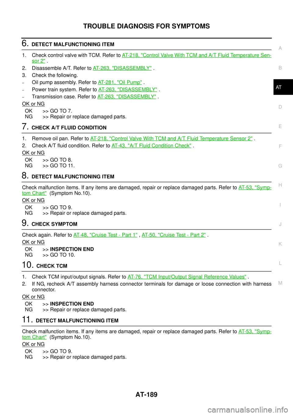
6.DETECT MALFUNCTIONING ITEM
1. Check control valve with TCM. Refer toAT- 2 1 8 , "
Control Valve With TCM and A/T Fluid Temperature Sen-
sor 2".
2. Disassemble A/T. Refer toAT- 2 6 3 , "
DISASSEMBLY".
3. Check the following.
–Oil pump assembly. Refer toAT- 2 8 1 , "Oil Pump".
–Power train system. Refer toAT- 2 6 3 , "DISASSEMBLY".
–Transmission case. Refer toAT- 2 6 3 , "DISASSEMBLY".
OK or NG
OK >> GO TO 7.
NG >> Repair or replace damaged parts.
7.CHECK A/T FLUID CONDITION
1. Remove oil pan. Refer toAT- 2 1 8 , "
Control Valve With TCM and A/T Fluid Temperature Sensor 2".
2. Check A/T fluid condition. Refer toAT-43, "
A/T Fluid Condition Check".
OK or NG
OK >> GO TO 8.
NG >> GO TO 11.
8.DETECT MALFUNCTIONING ITEM
Check malfunction items. If any items are damaged, repair or replace damaged parts. Refer toAT-53, "
Symp-
tom Chart"(Symptom No.10).
OK or NG
OK >> GO TO 9.
NG >> Repair or replace damaged parts.
9.CHECK SYMPTOM
Check again. Refer toAT-48, "
Cruise Test - Part 1",AT-50, "Cruise Test - Part 2".
OK or NG
OK >>INSPECTION END
NG >> GO TO 10.
10.CHECK TCM
1. Check TCM input/output signals. Refer toAT-76, "
TCM Input/Output Signal Reference Values".
2. If NG, recheck A/T assembly harness connector terminals for damage or loose connection with harness
connector.
OK or NG
OK >>INSPECTION END
NG >> Repair or replace damaged parts.
11 .DETECT MALFUNCTIONING ITEM
Check malfunction items. If any items are damaged, repair or replace damaged parts. Refer toAT-53, "
Symp-
tom Chart"(Symptom No.10).
OK or NG
OK >> GO TO 9.
NG >> Repair or replace damaged parts.
Page 199 of 3171
TROUBLE DIAGNOSIS FOR SYMPTOMS
AT-191
D
E
F
G
H
I
J
K
L
MA
B
AT
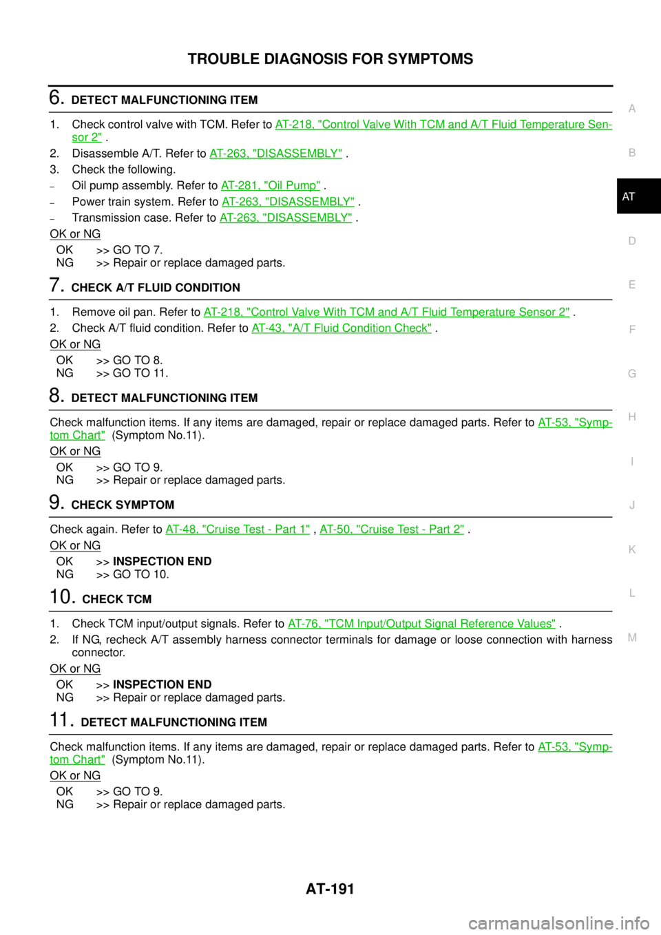
6.DETECT MALFUNCTIONING ITEM
1. Check control valve with TCM. Refer toAT- 2 1 8 , "
Control Valve With TCM and A/T Fluid Temperature Sen-
sor 2".
2. Disassemble A/T. Refer toAT- 2 6 3 , "
DISASSEMBLY".
3. Check the following.
–Oil pump assembly. Refer toAT- 2 8 1 , "Oil Pump".
–Power train system. Refer toAT- 2 6 3 , "DISASSEMBLY".
–Transmission case. Refer toAT- 2 6 3 , "DISASSEMBLY".
OK or NG
OK >> GO TO 7.
NG >> Repair or replace damaged parts.
7.CHECK A/T FLUID CONDITION
1. Remove oil pan. Refer toAT- 2 1 8 , "
Control Valve With TCM and A/T Fluid Temperature Sensor 2".
2. Check A/T fluid condition. Refer toAT-43, "
A/T Fluid Condition Check".
OK or NG
OK >> GO TO 8.
NG >> GO TO 11.
8.DETECT MALFUNCTIONING ITEM
Check malfunction items. If any items are damaged, repair or replace damaged parts. Refer toAT-53, "
Symp-
tom Chart"(Symptom No.11).
OK or NG
OK >> GO TO 9.
NG >> Repair or replace damaged parts.
9.CHECK SYMPTOM
Check again. Refer toAT-48, "
Cruise Test - Part 1",AT-50, "Cruise Test - Part 2".
OK or NG
OK >>INSPECTION END
NG >> GO TO 10.
10.CHECK TCM
1. Check TCM input/output signals. Refer toAT-76, "
TCM Input/Output Signal Reference Values".
2. If NG, recheck A/T assembly harness connector terminals for damage or loose connection with harness
connector.
OK or NG
OK >>INSPECTION END
NG >> Repair or replace damaged parts.
11 .DETECT MALFUNCTIONING ITEM
Check malfunction items. If any items are damaged, repair or replace damaged parts. Refer toAT-53, "
Symp-
tom Chart"(Symptom No.11).
OK or NG
OK >> GO TO 9.
NG >> Repair or replace damaged parts.