2005 NISSAN NAVARA timing belt
[x] Cancel search: timing beltPage 337 of 3171
ATC-3
C
D
E
F
G
H
I
K
L
MA
B
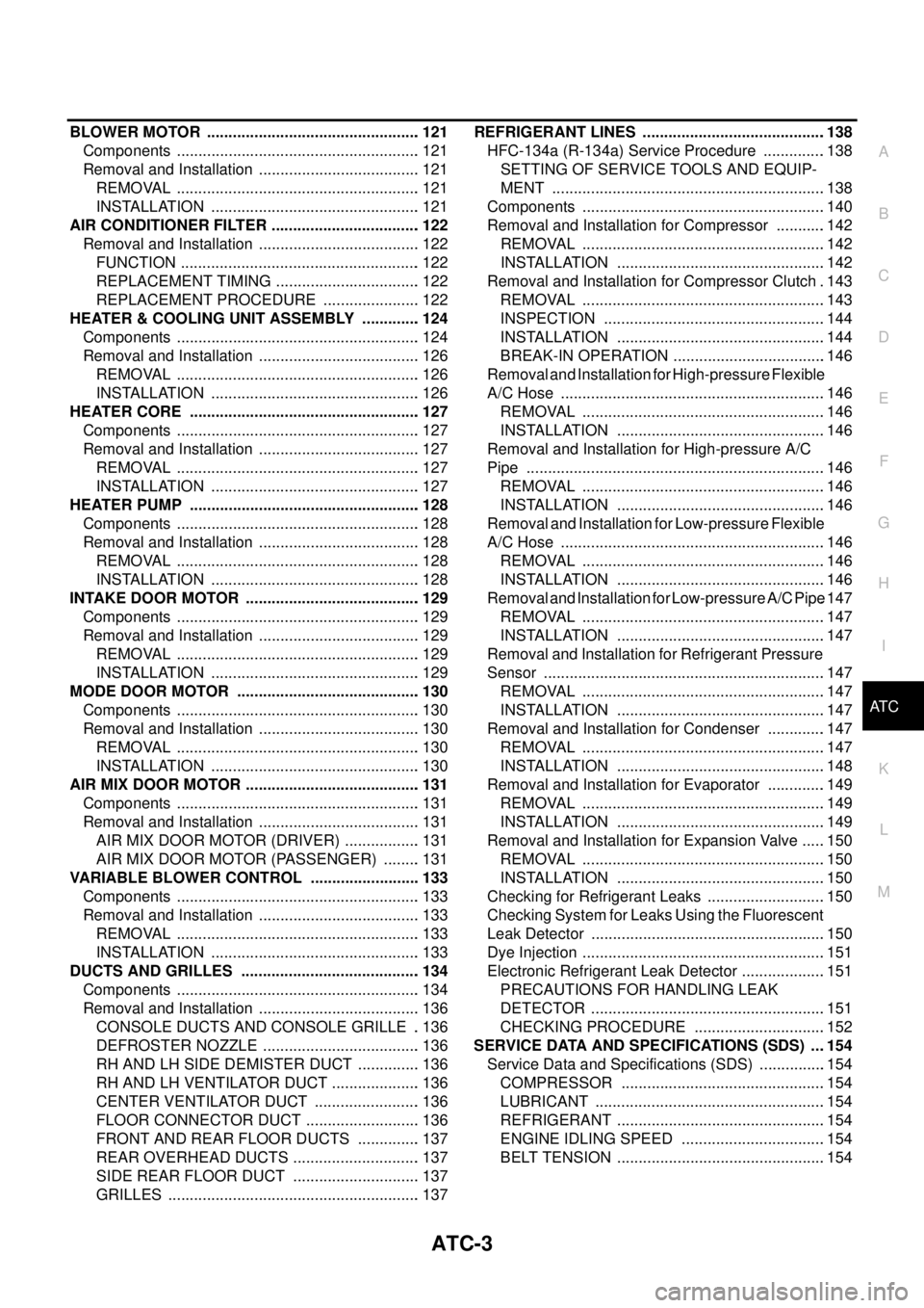
AT C BLOWER MOTOR .................................................. 121
Components ......................................................... 121
Removal and Installation ...................................... 121
REMOVAL ......................................................... 121
INSTALLATION ................................................. 121
AIR CONDITIONER FILTER ................................... 122
Removal and Installation ...................................... 122
FUNCTION ........................................................ 122
REPLACEMENT TIMING .................................. 122
REPLACEMENT PROCEDURE ....................... 122
HEATER & COOLING UNIT ASSEMBLY .............. 124
Components ......................................................... 124
Removal and Installation ...................................... 126
REMOVAL ......................................................... 126
INSTALLATION ................................................. 126
HEATER CORE ...................................................... 127
Components ......................................................... 127
Removal and Installation ...................................... 127
REMOVAL ......................................................... 127
INSTALLATION ................................................. 127
HEATER PUMP ...................................................... 128
Components ......................................................... 128
Removal and Installation ...................................... 128
REMOVAL ......................................................... 128
INSTALLATION ................................................. 128
INTAKE DOOR MOTOR ......................................... 129
Components ......................................................... 129
Removal and Installation ...................................... 129
REMOVAL ......................................................... 129
INSTALLATION ................................................. 129
MODE DOOR MOTOR ........................................... 130
Components ......................................................... 130
Removal and Installation ...................................... 130
REMOVAL ......................................................... 130
INSTALLATION ................................................. 130
AIR MIX DOOR MOTOR ......................................... 131
Components ......................................................... 131
Removal and Installation ...................................... 131
AIR MIX DOOR MOTOR (DRIVER) .................. 131
AIR MIX DOOR MOTOR (PASSENGER) ......... 131
VARIABLE BLOWER CONTROL .......................... 133
Components ......................................................... 133
Removal and Installation ...................................... 133
REMOVAL ......................................................... 133
INSTALLATION ................................................. 133
DUCTS AND GRILLES .......................................... 134
Components ......................................................... 134
Removal and Installation ...................................... 136
CONSOLE DUCTS AND CONSOLE GRILLE .. 136
DEFROSTER NOZZLE ..................................... 136
RH AND LH SIDE DEMISTER DUCT ............... 136
RH AND LH VENTILATOR DUCT ..................... 136
CENTER VENTILATOR DUCT ......................... 136
FLOOR CONNECTOR DUCT ........................... 136
FRONT AND REAR FLOOR DUCTS ............... 137
REAR OVERHEAD DUCTS .............................. 137
SIDE REAR FLOOR DUCT .............................. 137
GRILLES ........................................................... 137REFRIGERANT LINES ...........................................138
HFC-134a (R-134a) Service Procedure ...............138
SETTING OF SERVICE TOOLS AND EQUIP-
MENT ................................................................138
Components .........................................................140
Removal and Installation for Compressor ............142
REMOVAL .........................................................142
INSTALLATION .................................................142
Removal and Installation for Compressor Clutch . 143
REMOVAL .........................................................143
INSPECTION ....................................................144
INSTALLATION .................................................144
BREAK-IN OPERATION ....................................146
Removal and Installation for High-pressure Flexible
A/C Hose ..............................................................146
REMOVAL .........................................................146
INSTALLATION .................................................146
Removal and Installation for High-pressure A/C
Pipe ......................................................................146
REMOVAL .........................................................146
INSTALLATION .................................................146
Removal and Installation for Low-pressure Flexible
A/C Hose ..............................................................146
REMOVAL .........................................................146
INSTALLATION .................................................146
Removal and Installation for Low-pressure A/C Pipe.147
REMOVAL .........................................................147
INSTALLATION .................................................147
Removal and Installation for Refrigerant Pressure
Sensor ..................................................................147
REMOVAL .........................................................147
INSTALLATION .................................................147
Removal and Installation for Condenser ..............147
REMOVAL .........................................................147
INSTALLATION .................................................148
Removal and Installation for Evaporator ..............149
REMOVAL .........................................................149
INSTALLATION .................................................149
Removal and Installation for Expansion Valve ......150
REMOVAL .........................................................150
INSTALLATION .................................................150
Checking for Refrigerant Leaks ............................150
Checking System for Leaks Using the Fluorescent
Leak Detector .......................................................150
Dye Injection .........................................................151
Electronic Refrigerant Leak Detector ....................151
PRECAUTIONS FOR HANDLING LEAK
DETECTOR .......................................................151
CHECKING PROCEDURE ...............................152
SERVICE DATA AND SPECIFICATIONS (SDS) ....154
Service Data and Specifications (SDS) ................154
COMPRESSOR ................................................154
LUBRICANT ......................................................154
REFRIGERANT .................................................154
ENGINE IDLING SPEED ..................................154
BELT TENSION .................................................154
Page 476 of 3171
ATC-142
REFRIGERANT LINES
Removal and Installation for Compressor
EJS006CN
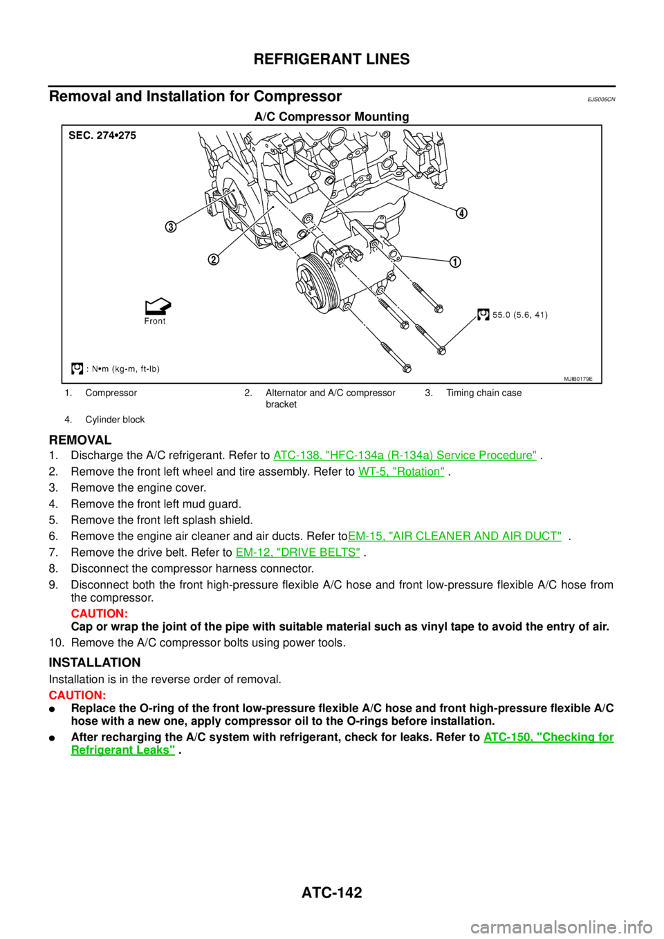
A/C Compressor Mounting
REMOVAL
1. Discharge the A/C refrigerant. Refer toATC-138, "HFC-134a (R-134a) Service Procedure".
2. Remove the front left wheel and tire assembly. Refer toWT-5, "
Rotation".
3. Remove the engine cover.
4. Remove the front left mud guard.
5. Remove the front left splash shield.
6. Remove the engine air cleaner and air ducts. Refer toEM-15, "
AIR CLEANER AND AIR DUCT".
7. Remove the drive belt. Refer toEM-12, "
DRIVE BELTS".
8. Disconnect the compressor harness connector.
9. Disconnect both the front high-pressure flexible A/C hose and front low-pressure flexible A/C hose from
the compressor.
CAUTION:
Cap or wrap the joint of the pipe with suitable material such as vinyl tape to avoid the entry of air.
10. Remove the A/C compressor bolts using power tools.
INSTALLATION
Installation is in the reverse order of removal.
CAUTION:
lReplace the O-ring of the front low-pressure flexible A/C hose and front high-pressure flexible A/C
hose with a new one, apply compressor oil to the O-rings before installation.
lAfter recharging the A/C system with refrigerant, check for leaks. Refer toATC-150, "Checking for
Refrigerant Leaks".
MJIB0179E
1. Compressor 2. Alternator and A/C compressor
bracket3. Timing chain case
4. Cylinder block
Page 981 of 3171
EC-1
ENGINE CONTROL SYSTEM
B ENGINE
CONTENTS
C
D
E
F
G
H
I
J
K
L
M
SECTIONEC
A
EC
ENGINE CONTROL SYSTEM
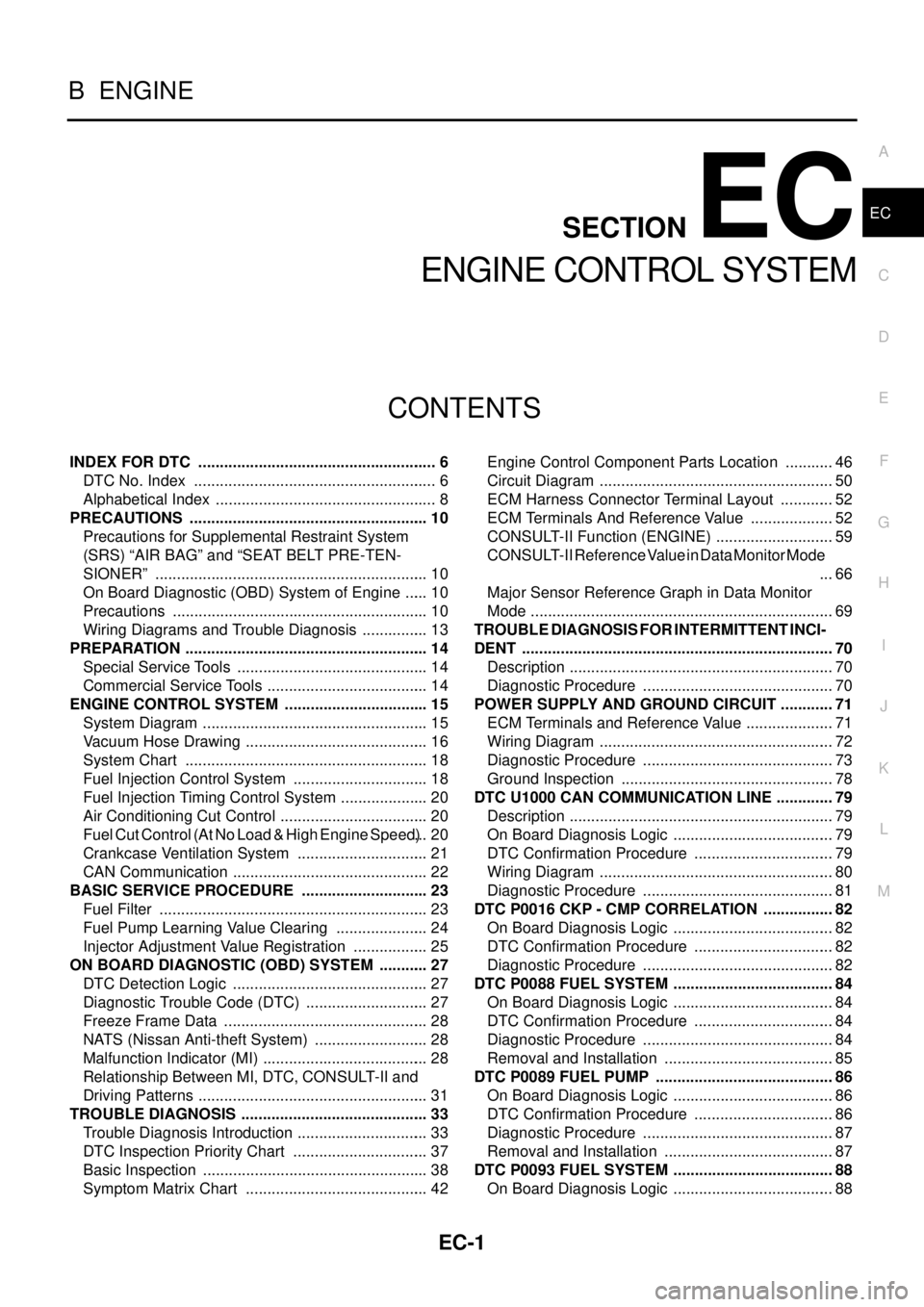
INDEX FOR DTC ........................................................ 6
DTC No. Index ......................................................... 6
Alphabetical Index .................................................... 8
PRECAUTIONS ........................................................ 10
Precautions for Supplemental Restraint System
(SRS)“AIRBAG”and“SEATBELTPRE-TEN-
SIONER” ................................................................ 10
On Board Diagnostic (OBD) System of Engine ...... 10
Precautions ............................................................ 10
Wiring Diagrams and Trouble Diagnosis ................ 13
PREPARATION ......................................................... 14
Special Service Tools ............................................. 14
Commercial Service Tools ...................................... 14
ENGINE CONTROL SYSTEM .................................. 15
System Diagram ..................................................... 15
Vacuum Hose Drawing ........................................... 16
System Chart ......................................................... 18
Fuel Injection Control System ................................ 18
Fuel Injection Timing Control System ..................... 20
Air Conditioning Cut Control ................................... 20
Fuel Cut Control (At No Load & High Engine Speed)... 20
Crankcase Ventilation System ............................... 21
CAN Communication .............................................. 22
BASIC SERVICE PROCEDURE .............................. 23
Fuel Filter ............................................................... 23
Fuel Pump Learning Value Clearing ...................... 24
Injector Adjustment Value Registration .................. 25
ON BOARD DIAGNOSTIC (OBD) SYSTEM ............ 27
DTC Detection Logic .............................................. 27
Diagnostic Trouble Code (DTC) ............................. 27
Freeze Frame Data ................................................ 28
NATS (Nissan Anti-theft System) ........................... 28
Malfunction Indicator (MI) ....................................... 28
Relationship Between MI, DTC, CONSULT-II and
Driving Patterns ...................................................... 31
TROUBLE DIAGNOSIS ............................................ 33
Trouble Diagnosis Introduction ............................... 33
DTC Inspection Priority Chart ................................ 37
Basic Inspection ..................................................... 38
Symptom Matrix Chart ........................................... 42Engine Control Component Parts Location ............ 46
Circuit Diagram ....................................................... 50
ECM Harness Connector Terminal Layout ............. 52
ECM Terminals And Reference Value .................... 52
CONSULT-II Function (ENGINE) ............................ 59
CONSULT-II Reference Value in Data Monitor Mode
... 66
Major Sensor Reference Graph in Data Monitor
Mode ....................................................................... 69
TROUBLE DIAGNOSIS FOR INTERMITTENT INCI-
DENT ......................................................................... 70
Description .............................................................. 70
Diagnostic Procedure ............................................. 70
POWER SUPPLY AND GROUND CIRCUIT ............. 71
ECM Terminals and Reference Value ..................... 71
Wiring Diagram ....................................................... 72
Diagnostic Procedure ............................................. 73
Ground Inspection .................................................. 78
DTC U1000 CAN COMMUNICATION LINE .............. 79
Description .............................................................. 79
On Board Diagnosis Logic ...................................... 79
DTC Confirmation Procedure ................................. 79
Wiring Diagram ....................................................... 80
Diagnostic Procedure ............................................. 81
DTC P0016 CKP - CMP CORRELATION ................. 82
On Board Diagnosis Logic ...................................... 82
DTC Confirmation Procedure ................................. 82
Diagnostic Procedure ............................................. 82
DTC P0088 FUEL SYSTEM ...................................... 84
On Board Diagnosis Logic ...................................... 84
DTC Confirmation Procedure ................................. 84
Diagnostic Procedure ............................................. 84
Removal and Installation ........................................ 85
DTC P0089 FUEL PUMP .......................................... 86
On Board Diagnosis Logic ...................................... 86
DTC Confirmation Procedure ................................. 86
Diagnostic Procedure ............................................. 87
Removal and Installation ........................................ 87
DTC P0093 FUEL SYSTEM ...................................... 88
On Board Diagnosis Logic ...................................... 88
Page 1393 of 3171
NOISE, VIBRATION AND HARSHNESS (NVH) TROUBLESHOOTING
EM-11
C
D
E
F
G
H
I
J
K
L
MA
EM
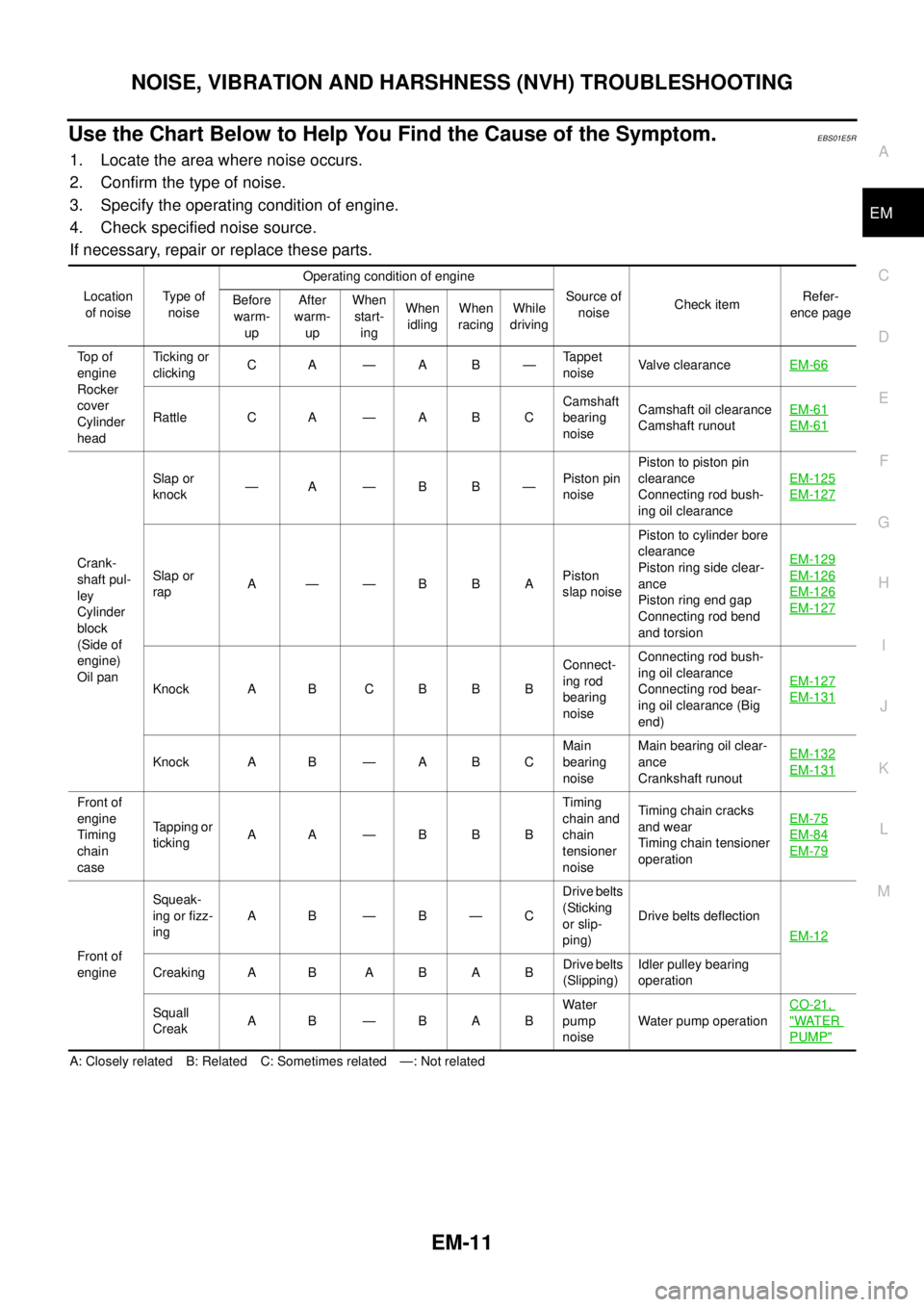
Use the Chart Below to Help You Find the Cause of the Symptom.EBS01E5R
1. Locate the area where noise occurs.
2. Confirm the type of noise.
3. Specify the operating condition of engine.
4. Check specified noise source.
If necessary, repair or replace these parts.
A: Closely related B: Related C: Sometimes related —: Not relatedLocation
of noiseType of
noiseOperating condition of engine
Source of
noiseCheck itemRefer-
ence page Before
warm-
upAfter
warm-
upWhen
start-
ingWhen
idlingWhen
racingWhile
driving
To p o f
engine
Rocker
cover
Cylinder
headTicking or
clickingCA—AB—Tappet
noiseValve clearanceEM-66
Rattle C A — A B CCamshaft
bearing
noiseCamshaft oil clearance
Camshaft runoutEM-61EM-61
Crank-
shaft pul-
ley
Cylinder
block
(Side of
engine)
Oil panSlap or
knock—A—BB—Piston pin
noisePiston to piston pin
clearance
Connecting rod bush-
ing oil clearanceEM-125
EM-127
Slap or
rapA ——BBAPiston
slap noisePiston to cylinder bore
clearance
Piston ring side clear-
ance
Piston ring end gap
Connecting rod bend
and torsionEM-129EM-126
EM-126
EM-127
Knock A B C B B BConnect-
ing rod
bearing
noiseConnecting rod bush-
ing oil clearance
Connecting rod bear-
ing oil clearance (Big
end)EM-127EM-131
Knock A B — A B CMain
bearing
noiseMain bearing oil clear-
ance
Crankshaft runoutEM-132EM-131
Front of
engine
Timing
chain
caseTapping or
tickingA A —BBBTiming
chain and
chain
tensioner
noiseTiming chain cracks
and wear
Timing chain tensioner
operationEM-75
EM-84
EM-79
Front of
engineSqueak-
ing or fizz-
ingAB—B—CDrive belts
(Sticking
or slip-
ping)Drive belts deflection
EM-12
CreakingA B ABABDrive belts
(Slipping)Idler pulley bearing
operation
Squall
CreakA B —BABWater
pump
noiseWater pump operationCO-21,
"WATER
PUMP"
Page 1453 of 3171
OIL SEAL
EM-71
C
D
E
F
G
H
I
J
K
L
MA
EM
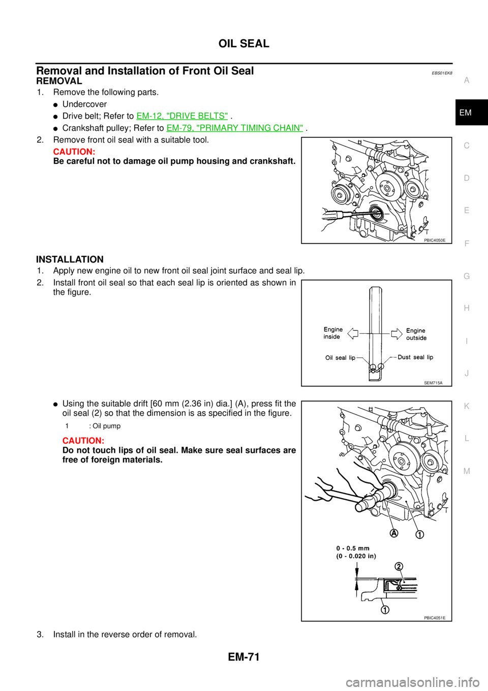
Removal and Installation of Front Oil SealEBS01EK8
REMOVAL
1. Remove the following parts.
lUndercover
lDrive belt; Refer toEM-12, "DRIVE BELTS".
lCrankshaft pulley; Refer toEM-79, "PRIMARY TIMING CHAIN".
2. Remove front oil seal with a suitable tool.
CAUTION:
Be careful not to damage oil pump housing and crankshaft.
INSTALLATION
1. Apply new engine oil to new front oil seal joint surface and seal lip.
2. Install front oil seal so that each seal lip is oriented as shown in
the figure.
lUsing the suitable drift [60 mm (2.36 in) dia.] (A), press fit the
oil seal (2) so that the dimension is as specified in the figure.
CAUTION:
Do not touch lips of oil seal. Make sure seal surfaces are
free of foreign materials.
3. Install in the reverse order of removal.
PBIC4050E
SEM715A
1 : Oil pump
PBIC4051E
Page 1455 of 3171
SECONDARY TIMING CHAIN
EM-73
C
D
E
F
G
H
I
J
K
L
MA
EM
SECONDARY TIMING CHAINPFP:13028
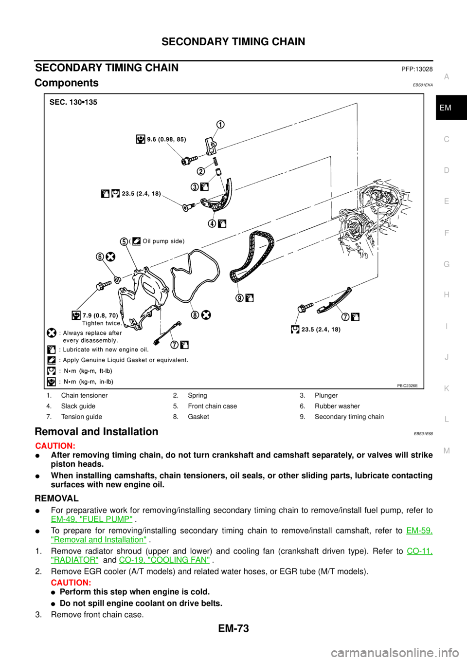
ComponentsEBS01EKA
Removal and InstallationEBS01E68
CAUTION:
lAfter removing timing chain, do not turn crankshaft and camshaft separately, or valves will strike
piston heads.
lWhen installing camshafts, chain tensioners, oil seals, or other sliding parts, lubricate contacting
surfaces with new engine oil.
REMOVAL
lFor preparative work for removing/installing secondary timing chain to remove/install fuel pump, refer to
EM-49, "
FUEL PUMP".
lTo prepare for removing/installing secondary timing chain to remove/install camshaft, refer toEM-59,
"Removal and Installation".
1. Remove radiator shroud (upper and lower) and cooling fan (crankshaft driven type). Refer toCO-11,
"RADIATOR"andCO-19, "COOLING FAN".
2. Remove EGR cooler (A/T models) and related water hoses, or EGR tube (M/T models).
CAUTION:
lPerform this step when engine is cold.
lDo not spill engine coolant on drive belts.
3. Remove front chain case.
1. Chain tensioner 2. Spring 3. Plunger
4. Slack guide 5. Front chain case 6. Rubber washer
7. Tension guide 8. Gasket 9. Secondary timing chain
PBIC2326E
Page 1517 of 3171
SERVICE DATA AND SPECIFICATIONS (SDS)
EM-135
C
D
E
F
G
H
I
J
K
L
MA
EM
SERVICE DATA AND SPECIFICATIONS (SDS)PFP:00030
Standard and LimitEBS01E6H
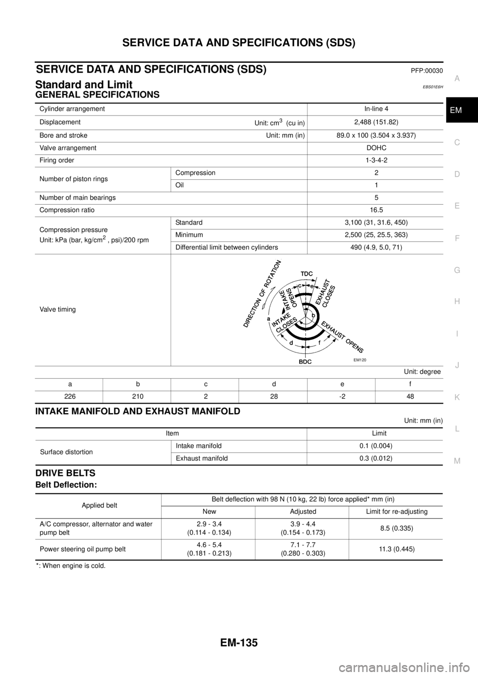
GENERAL SPECIFICATIONS
INTAKE MANIFOLD AND EXHAUST MANIFOLD
Unit: mm (in)
DRIVE BELTS
Belt Deflection:
*: When engine is cold.Cylinder arrangementIn-line 4
Displacement
Unit: cm
3(cu in)2,488 (151.82)
Bore and stroke Unit: mm (in) 89.0 x 100 (3.504 x 3.937)
Valve arrangementDOHC
Firing order1-3-4-2
Number of piston ringsCompression 2
Oil 1
Number of main bearings5
Compression ratio16.5
Compression pressure
Unit: kPa (bar, kg/cm
2, psi)/200 rpmStandard 3,100 (31, 31.6, 450)
Minimum 2,500 (25, 25.5, 363)
Differential limit between cylinders 490 (4.9, 5.0, 71)
Valve timing
Unit: degree
abc de f
226 210 2 28 -2 48
EM120
Item Limit
Surface distortionIntake manifold 0.1 (0.004)
Exhaust manifold 0.3 (0.012)
Applied beltBelt deflection with 98 N (10 kg, 22 lb) force applied* mm (in)
New Adjusted Limit for re-adjusting
A/C compressor, alternator and water
pump belt2.9 - 3.4
(0.114 - 0.134)3.9 - 4.4
(0.154 - 0.173)8.5 (0.335)
Power steering oil pump belt4.6 - 5.4
(0.181 - 0.213)7.1 - 7.7
(0.280 - 0.303)11.3 (0.445)
Page 2509 of 3171
MTC-122
REFRIGERANT LINES
Removal and Installation for Compressor
EJS005HC
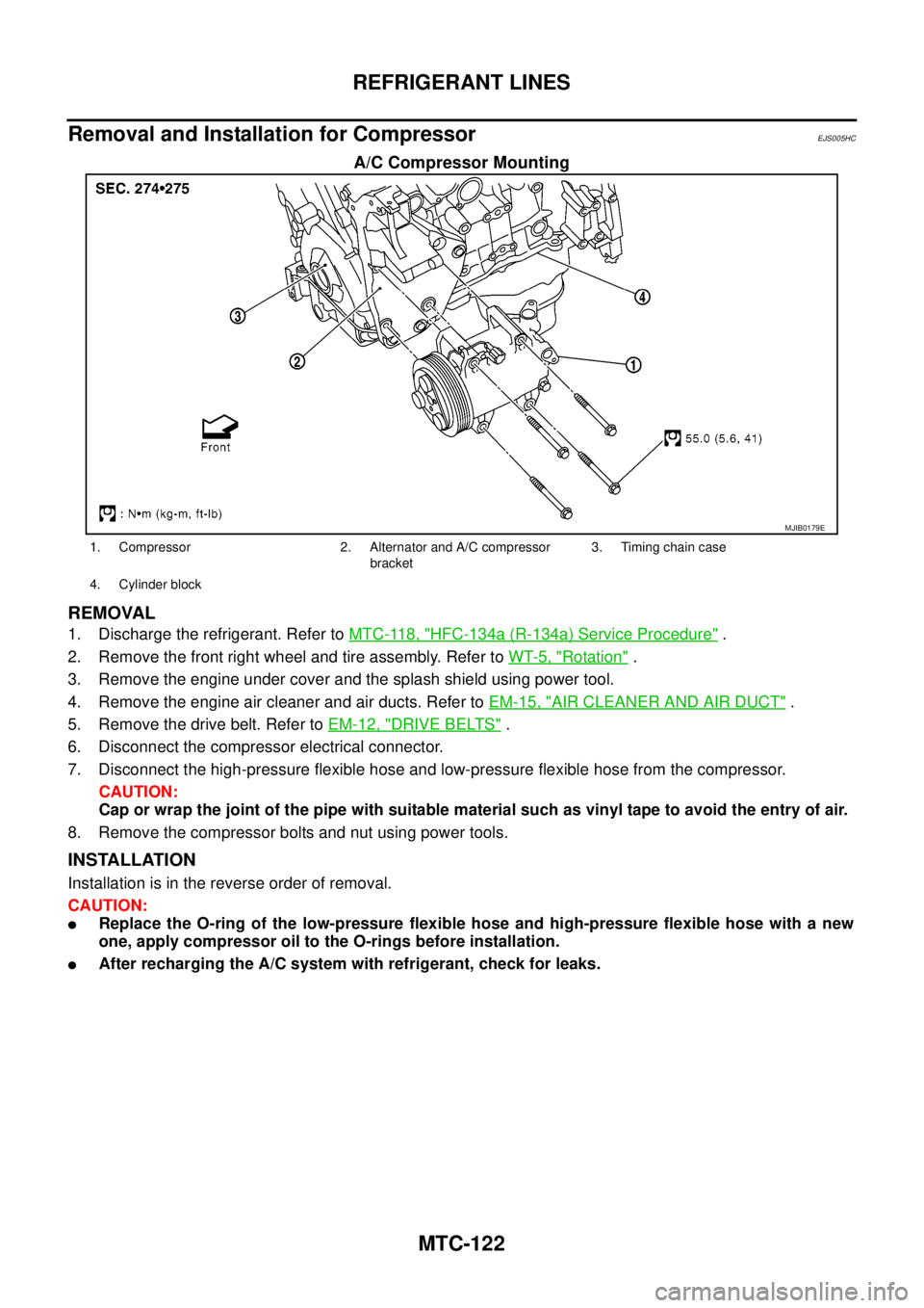
A/C Compressor Mounting
REMOVAL
1. Discharge the refrigerant. Refer toMTC-118, "HFC-134a (R-134a) Service Procedure".
2. Remove the front right wheel and tire assembly. Refer toWT-5, "
Rotation".
3. Remove the engine under cover and the splash shield using power tool.
4. Remove the engine air cleaner and air ducts. Refer toEM-15, "
AIR CLEANER AND AIR DUCT".
5. Remove the drive belt. Refer toEM-12, "
DRIVE BELTS".
6. Disconnect the compressor electrical connector.
7. Disconnect the high-pressure flexible hose and low-pressure flexible hose from the compressor.
CAUTION:
Cap or wrap the joint of the pipe with suitable material such as vinyl tape to avoid the entry of air.
8. Remove the compressor bolts and nut using power tools.
INSTALLATION
Installation is in the reverse order of removal.
CAUTION:
lReplace the O-ring of the low-pressure flexible hose and high-pressure flexible hose with a new
one, apply compressor oil to the O-rings before installation.
lAfter recharging the A/C system with refrigerant, check for leaks.
MJIB0179E
1. Compressor 2. Alternator and A/C compressor
bracket3. Timing chain case
4. Cylinder block