2005 NISSAN NAVARA mirror
[x] Cancel search: mirrorPage 1 of 3171
MODELD40 SERIES
2005 NISSAN EUROPE S.A.S.
All rights reserved. No part of this Electronic Service Manual may be reproduced or stored in a retrieval system, or transmitted in any
form, or by any means, electronic, mechanical, photocopying, recording or otherwise, without the prior written permission of Nissan
Europe S.A.S., Paris, France.
A GENERAL INFORMATION
B ENGINE
C TRANSMISSION/TRANSAXLE
D DRIVELINE/AXLE
E SUSPENSION F BRAKES
G STEERING H RESTRAINTS
I BODY
J AIR CONDITIONER
K ELECTRICAL
L MAINTENANCE
M INDEXGI General Information
EM Engine Mechanical
LU Engine Lubrication System
CO Engine Cooling System
EC Engine Control System
FL Fuel System
EX Exhaust System
ACC Accelerator Control System
CL Clutch
MTManualTransmission
AT Automatic Transmission
TF Transfer
PR Propeller Shaft
FFD Front Final Drive
RFD Rear Final Drive
FAX Front Axle
RAX Rear Axle
FSU Front Suspension
RSU Rear Suspension
WT Road Wheels & Tires
BR Brake System
PB Parking Brake System
BRC Brake Control System
PS Power Steering System
SB Seat Belts
SRS Supplemental Restraint System (SRS)
BL Body, Lock & Security System
GW Glasses, Window System & Mirrors
RF Roof
EI Exterior & Interior
IP Instrument Panel
SE Seat
ATC Automatic Air Conditioner
MTC Manual Air Conditioner
SC Starting & Charging System
LT Lighting System
DI Driver Information System
WW Wiper, Washer & Horn
BCS Body Control System
LAN LAN System
AV Audio, Visual & Telephone System
ACS Auto Cruise Control System
PG Power Supply, Ground & Circuit Elements
MA Maintenance
IDX Alphabetical Index
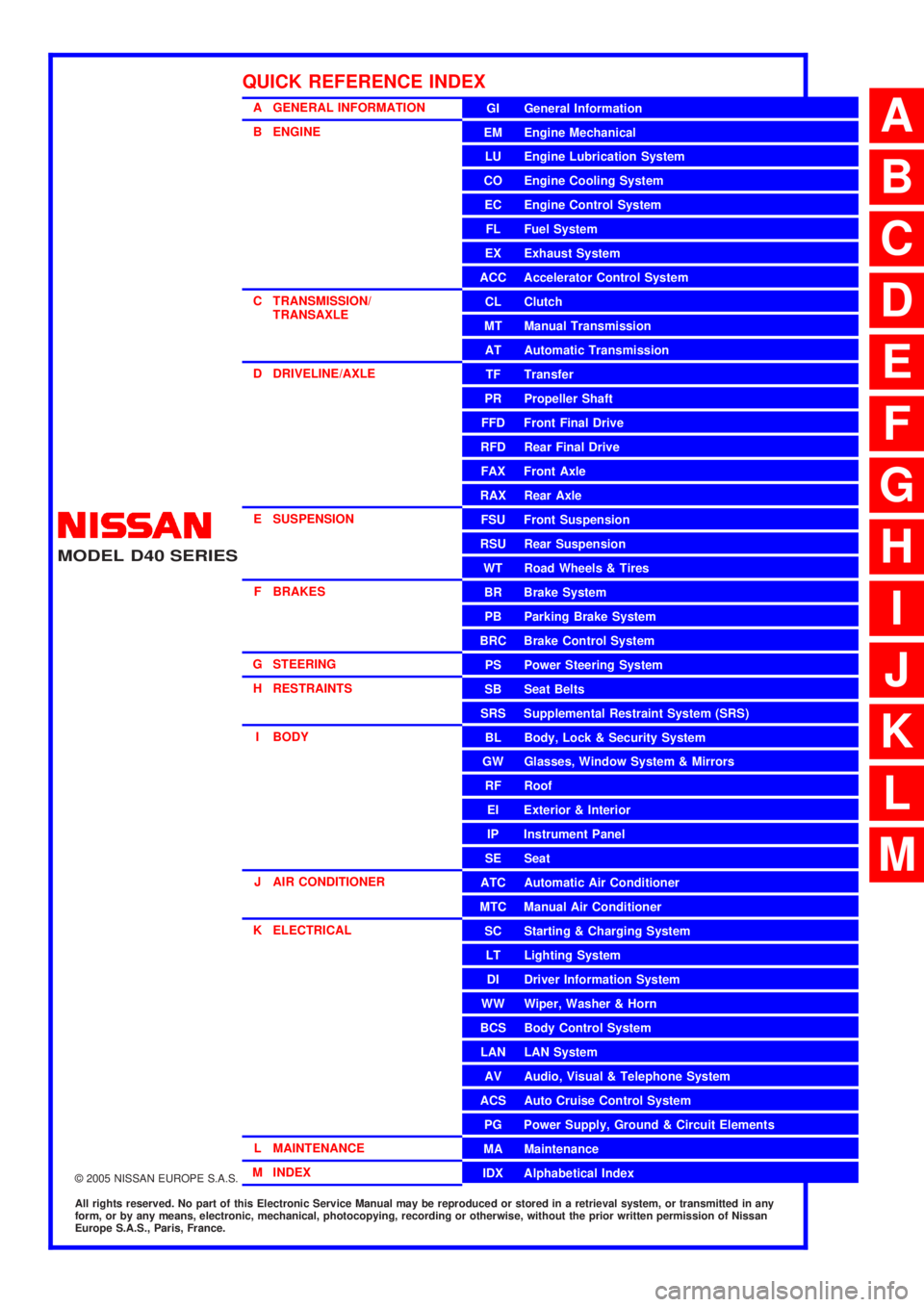
QUICK REFERENCE INDEX
A
B
C
D
E
F
G
H
I
J
K
L
M
Page 388 of 3171

ATC-54
TROUBLE DIAGNOSIS
19 GR Power supply for BAT - - Battery voltage
20 B Ground - - 0V
21 V Mode door motor feedback ON - 0 - 5V
22 SB Air mix door motor (Driver) feedback ON - 0 - 5V
23 G Sensor power ON - 5V
26 P Sensor return ON - 0V
27 R In-vehicle sensor signal ON - 0 - 5V
28 W Ambient sensor ON - 0 - 5V
29 G Optical sensor (Driver) ON - 0 - 5V
31 PPTC heater relay 1
(LHD models)ONRelay ON Battery voltage
Relay OFF 0V
32 V Variable blower control ON - 0 - 5V
33 BR In-vehicle sensor motor (+) ON - Battery voltage
34 O In-vehicle sensor motor (-) ON - 0V
35 LG Fan ON signalON Blower switch OFF 5V
ON Blower switch ON 0V
36 SBAir mix door motor (Passenger)
feedbackON - 0 - 5V
37 GR Optical sensor (Passenger) ON - 0 - 5V
38 B Blower request ONBlower motor OFF Battery voltage
Blower motor ON 0V
40 LGPTC heater relay 2
(LHD models)ONRelay ON Battery voltage
Relay OFF 0V
41 L CAN-H ON - 0 - 5V
42 P CAN-L ON - 0 - 5V
43 BRPTC heater relay 3
(LHD models)ONRelay ON Battery voltage
Relay OFF 0V
44 R Mirror heater (LHD models) ONHeater OFF 0V
Heater ON Battery voltage Te r m i -
nal No.Wire
colorItemIgnition
switchConditionVoltage (V)
(Approx.)
Page 484 of 3171
ATC-150
REFRIGERANT LINES
CAUTION:
Replace the O-rings on the A/C low-pressure flexible A/C hose and the high-pressure A/C pipe with
new ones. Apply compressor oil to the O-rings for installation.
Removal and Installation for Expansion ValveEJS006CZ
REMOVAL
1. Discharge the refrigerant. Refer toATC-138, "HFC-134a (R-134a) Service Procedure".
2. Remove the heater and cooling unit assembly. Refer toATC-126, "
REMOVAL".
3. Remove the heater core and evaporator pipes grommet.
4. Remove the expansion valve.
INSTALLATION
Installation is in the reverse order of removal.
CAUTION:
lReplace the O-rings on then expansion valve and the A/C refrigerant pipes with new ones, then
apply compressor oil to them for installation.
lAfter charging refrigerant, check for leaks.
Checking for Refrigerant LeaksEJS006D1
Perform a visual inspection of all refrigeration parts, fittings, hoses and components for signs of A/C lubricant
leakage, damage and corrosion. A/C lubricant leakage may indicate an area of refrigerant leakage. Allow
extra inspection time in these areas when using either an electronic refrigerant leak detector or fluorescent
dye leak detector.
If dye is observed, confirm the leak with an electronic refrigerant leak detector. It is possible a prior leak was
repaired and not properly cleaned.
When searching for leaks, do not stop when one leak is found but continue to check for additional leaks at all
system components and connections.
When searching for refrigerant leaks using an electronic leak detector, move the probe along the suspected
leak area at 1 to 2 inches per second and no further than 1/4 inch from the component.
CAUTION:
Moving the electronic leak detector probe slower and closer to the suspected leak area will improve
the chances of finding a leak.
Checking System for Leaks Using the Fluorescent Leak DetectorEJS006D2
1. Check A/C system for leaks using the UV lamp and safety goggles [SST: J-42220] in a low sunlight area
(area without windows preferable). Illuminate all components, fittings and lines. The dye will appear as a
bright green/yellow area at the point of leakage. Fluorescent dye observed at the evaporator drain open-
ing indicates an evaporator core assembly (tubes, core or expansion valve) leak.
2. If the suspected area is difficult to see, use an adjustable mirror or wipe the area with a clean shop rag or
cloth, with the UV lamp for dye residue.
3. After the leak is repaired, remove any residual dye using dye cleaner [SST: J-43872] to prevent future mis-
diagnosis.
4. Perform a system performance check and verify the leak repair with an approved electronic refrigerant
leak detector.
NOTE:
Other gases in the work area or substances on the A/C components, for example, anti-freeze, windshield
washer fluid, solvents and lubricants, may falsely trigger the leak detector. Make sure the surfaces to be
checked are clean.
Cleanwithadryclothorblowoffwithshopair.
Do not allow the sensor tip of the detector to contact with any substance. This can also cause false readings
and may damage the detector.Expansion valve bolts : 4 N·m (0.41 kg-m, 35 in-lb)
A/C refrigerant pipe to expansion valve bolt : Refer toATC-140, "
Components"
.
Page 976 of 3171
DI-66
COMPASS
COMPASS
PFP:24835
System DescriptionEKS00M4Z
This unit displays earth magnetism and heading direction of vehicle.
DIRECTION DISPLAY
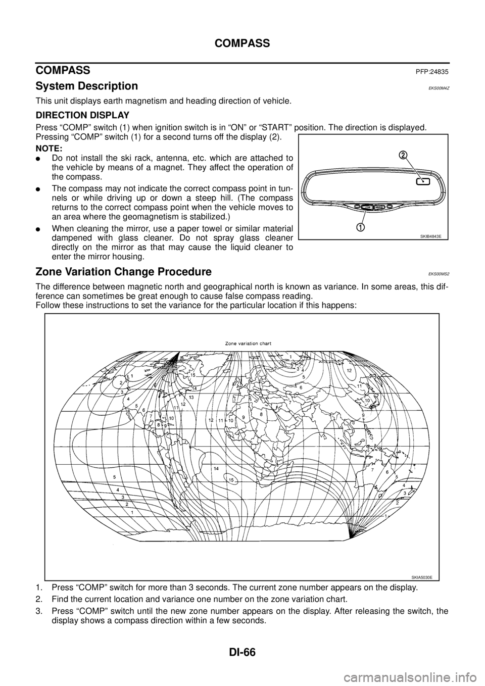
Press “COMP” switch (1) when ignition switch is in “ON” or “START” position. The direction is displayed.
Pressing “COMP” switch (1) for a second turns off the display (2).
NOTE:
lDo not install the ski rack, antenna, etc. which are attached to
the vehicle by means of a magnet. They affect the operation of
the compass.
lThe compass may not indicate the correct compass point in tun-
nels or while driving up or down a steep hill. (The compass
returns to the correct compass point when the vehicle moves to
an area where the geomagnetism is stabilized.)
lWhen cleaning the mirror, use a paper towel or similar material
dampened with glass cleaner. Do not spray glass cleaner
directly on the mirror as that may cause the liquid cleaner to
enter the mirror housing.
Zone Variation Change ProcedureEKS00MS2
The difference between magnetic north and geographical north is known as variance. In some areas, this dif-
ference can sometimes be great enough to cause false compass reading.
Follow these instructions to set the variance for the particular location if this happens:
1. Press “COMP” switch for more than 3 seconds. The current zone number appears on the display.
2. Find the current location and variance one number on the zone variation chart.
3. Press “COMP” switch until the new zone number appears on the display. After releasing the switch, the
display shows a compass direction within a few seconds.
SKIB4843E
SKIA5030E
Page 1365 of 3171
DOOR OUTSIDE MOLDING
EI-27
C
D
E
F
G
H
J
K
L
MA
B
EI
DOOR OUTSIDE MOLDINGPFP:82820
Removal and InstallationEIS00DYK
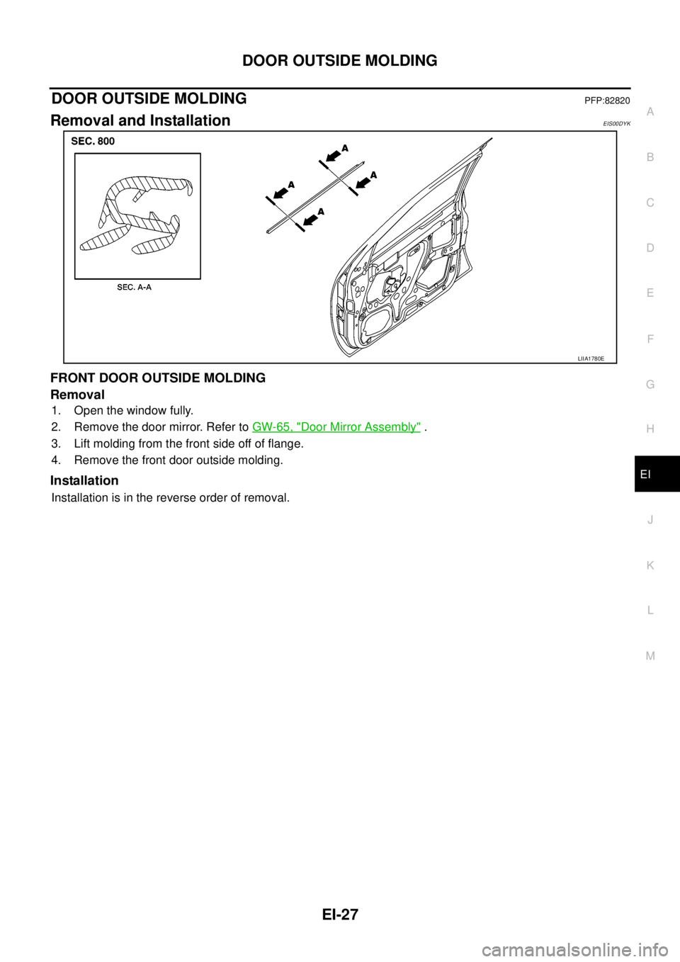
FRONT DOOR OUTSIDE MOLDING
Removal
1. Open the window fully.
2. Remove the door mirror. Refer toGW-65, "
Door Mirror Assembly".
3. Lift molding from the front side off of flange.
4. Remove the front door outside molding.
Installation
Installation is in the reverse order of removal.
LIIA1780E
Page 1379 of 3171
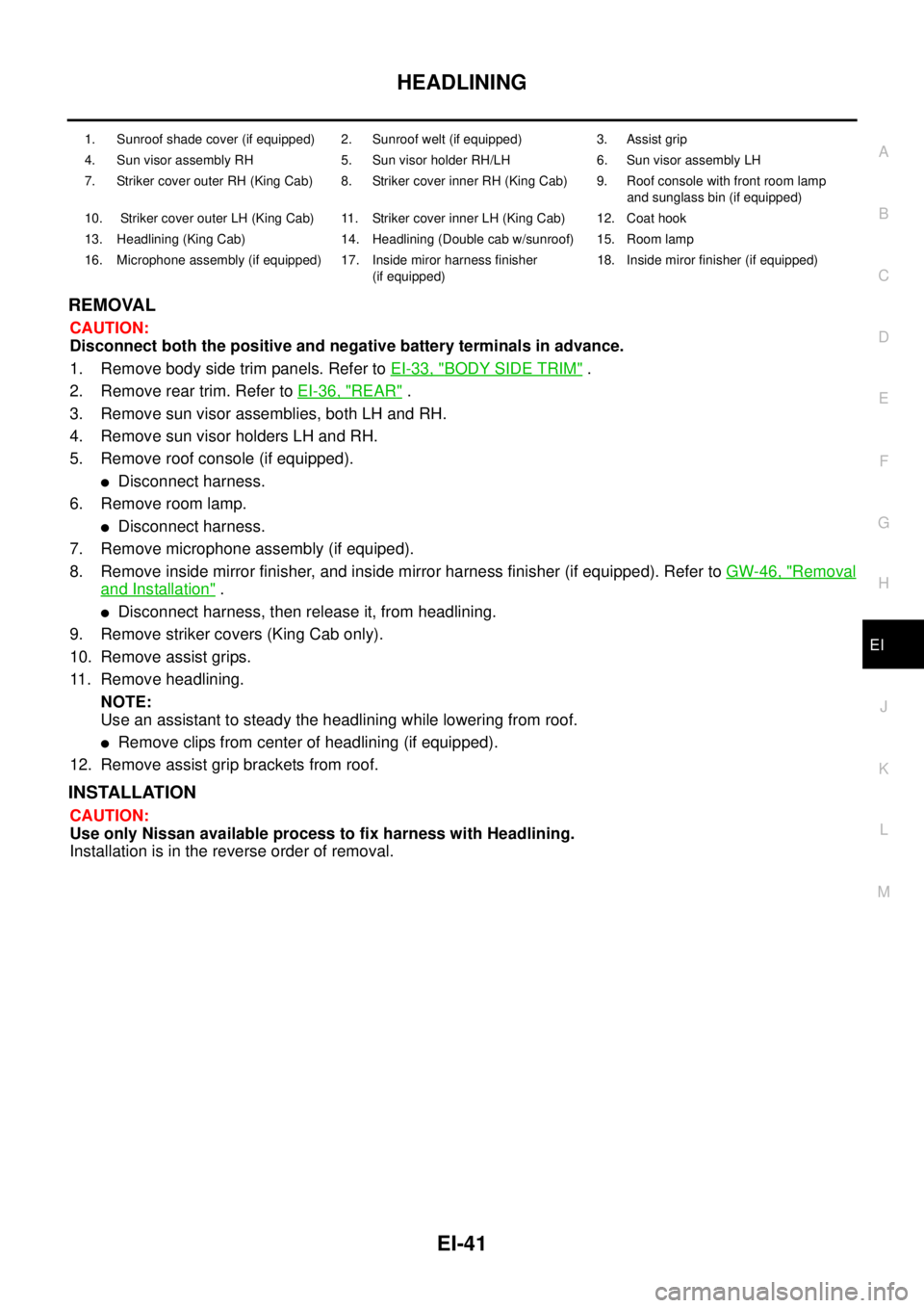
HEADLINING
EI-41
C
D
E
F
G
H
J
K
L
MA
B
EI
REMOVAL
CAUTION:
Disconnect both the positive and negative battery terminals in advance.
1. Remove body side trim panels. Refer toEI-33, "
BODY SIDE TRIM".
2. Remove rear trim. Refer toEI-36, "
REAR".
3. Remove sun visor assemblies, both LH and RH.
4. Remove sun visor holders LH and RH.
5. Remove roof console (if equipped).
lDisconnect harness.
6. Remove room lamp.
lDisconnect harness.
7. Remove microphone assembly (if equiped).
8. Remove inside mirror finisher, and inside mirror harness finisher (if equipped). Refer toGW-46, "
Removal
and Installation".
lDisconnect harness, then release it, from headlining.
9. Remove striker covers (King Cab only).
10. Remove assist grips.
11. Remove headlining.
NOTE:
Use an assistant to steady the headlining while lowering from roof.
lRemove clips from center of headlining (if equipped).
12. Remove assist grip brackets from roof.
INSTALLATION
CAUTION:
Use only Nissan available process to fix harness with Headlining.
Installation is in the reverse order of removal.
1. Sunroof shade cover (if equipped) 2. Sunroof welt (if equipped) 3. Assist grip
4. Sun visor assembly RH 5. Sun visor holder RH/LH 6. Sun visor assembly LH
7. Striker cover outer RH (King Cab) 8. Striker cover inner RH (King Cab) 9. Roof console with front room lamp
and sunglass bin (if equipped)
10. Striker cover outer LH (King Cab) 11. Striker cover inner LH (King Cab) 12. Coat hook
13. Headlining (King Cab) 14. Headlining (Double cab w/sunroof) 15. Room lamp
16. Microphone assembly (if equipped) 17. Inside miror harness finisher
(if equipped)18. Inside miror finisher (if equipped)
Page 1407 of 3171

INTAKE MANIFOLD
EM-25
C
D
E
F
G
H
I
J
K
L
MA
EM
–When an insert stopper is not provided with the pipe, insert the hose up to dimension A. When the pipe is
shorter than dimension A, insert hose fully until it reaches the end.
–When an insert stopper is provided on the pipe side, insert the hose until it reaches the stopper.
lBefore starting engine, bleed air from fuel piping. Refer toFL-5, "Air Bleeding".
INSPECTION AFTER INSTALLATION
Start engine and increase engine speed to check for fuel leak.
CAUTION:
Do not touch the engine immediately after stopped as engine becomes extremely hot.
NOTE:
Use mirrors for checking at points out of clear sight.Dimension A : 15 – 20 mm (0.591 – 0.787 in)
Page 1478 of 3171
EM-96
CYLINDER HEAD
INSTALLATION
Before installation, remove old liquid gasket from mating surface of all liquid gasket applied parts.
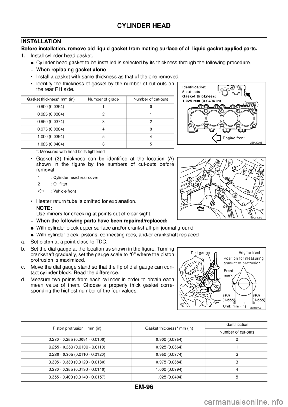
1. Install cylinder head gasket.
lCylinder head gasket to be installed is selected by its thickness through the following procedure.
–When replacing gasket alone
• Install a gasket with same thickness as that of the one removed.
• Identify the thickness of gasket by the number of cut-outs on
the rear RH side.
*: Measured with head bolts tightened
• Gasket (3) thickness can be identified at the location (A)
shown in the figure by the numbers of cut-outs before
removal.
• Heater return tube is omitted for explanation.
NOTE:
Use mirrors for checking at points out of clear sight.
–When the following parts have been repaired/replaced:
lWith cylinder block upper surface and/or crankshaft pin journal ground
lWith cylinder block, pistons, connecting rods, and/or crankshaft replaced
a. Set piston at a point close to TDC.
b. Set the dial gauge at the location as shown in the figure. Turning
crankshaft gradually, set the gauge scale to “0” where the piston
protrusion is maximized.
c. Movethedialgaugestandsothatthetipofdialgaugecancon-
tact cylinder block. Read the difference.
d. Measure two points from each cylinder in order to obtain each
mean value of them. Choose a properly thick gasket corre-
sponding the highest number of the four values.
Gasket thickness* mm (in) Number of grade Number of cut-outs
0.900 (0.0354) 1 0
0.925 (0.0364) 2 1
0.950 (0.0374) 3 2
0.975 (0.0384) 4 3
1.000 (0.0394) 5 4
1.025 (0.0404) 6 5
1 : Cylinder head rear cover
2:Oilfilter
: Vehicle front
MBIA0020E
PBIC3478E
SEM507G
Piston protrusion mm (in) Gasket thickness* mm (in)Identification
Number of cut-outs
0.230 - 0.255 (0.0091 - 0.0100) 0.900 (0.0354) 0
0.255 - 0.280 (0.0100 - 0.0110) 0.925 (0.0364) 1
0.280 - 0.305 (0.0110 - 0.0120) 0.950 (0.0374) 2
0.305 - 0.330 (0.0120 - 0.0130) 0.975 (0.0384) 3
0.330 - 0.355 (0.0130 - 0.0140) 1.000 (0.0394) 4
0.355 - 0.400 (0.0140 - 0.0157) 1.025 (0.0404) 5