2005 NISSAN NAVARA Em-42
[x] Cancel search: Em-42Page 1131 of 3171
DTC P0234 TC SYSTEM
EC-151
C
D
E
F
G
H
I
J
K
L
MA
EC
4.DETECT MALFUNCTIONING PART
Check the following.
lHarness connectors E9, F4
lHarness for open or short between IPDM E/R and turbocharger boost control solenoid valve
lHarness for open or short between ECM and turbocharger boost control solenoid valve
>> Repair open circuit or short to ground or short to power in harness or connectors.
5.CHECK TURBOCHARGER BOOST CONTROL SOLENOID VALVE OUTPUT SIGNAL CIRCUIT FOR
OPEN AND SHORT
1. Turn ignition switch OFF.
2. Disconnect ECM harness connector.
3. Check harness continuity between ECM terminals 6 and turbocharger boost control solenoid valve termi-
nal 2.
Refer to Wiring Diagram.
4. Also check harness for short to ground and short to power.
OK or NG
OK >> GO TO 6.
NG >> Repair open circuit or short to ground or short to power in harness or connectors.
6.CHECK TURBOCHARGE BOOST CONTROL SOLENOID VALVE
Refer toEC-152, "
Component Inspection".
OK or NG
OK >> GO TO 7.
NG >> Replace turbocharger boost control solenoid valve.
7.CHECK VACUUM PUMP
Refer toEM-42, "
VACUUM PUMP".
OK or NG
OK >> GO TO 8.
NG >> Replace vacuum pump assembly.
8.CHECK TURBOCHARGER BOOST CONTROL ACTUATOR
1. Turn ignition switch OFF.
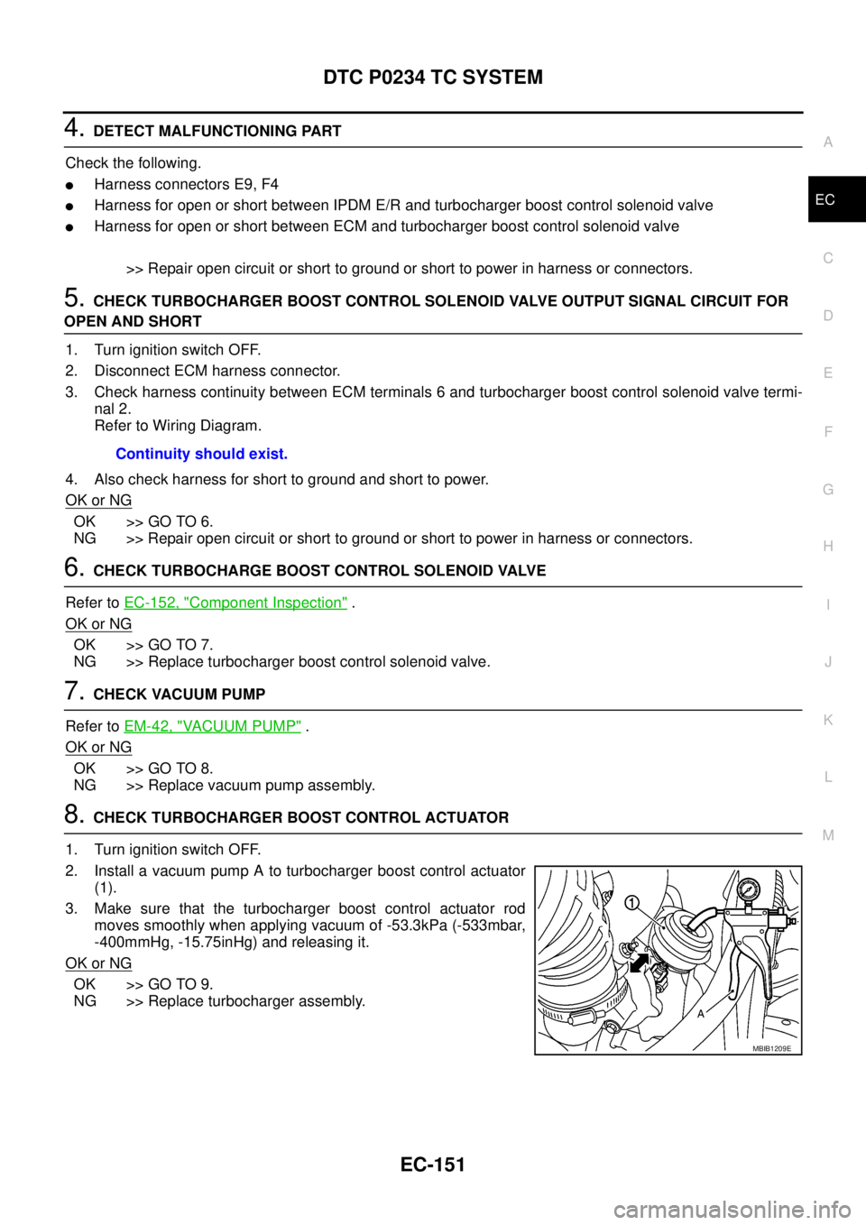
2. Install a vacuum pump A to turbocharger boost control actuator
(1).
3. Make sure that the turbocharger boost control actuator rod
moves smoothly when applying vacuum of -53.3kPa (-533mbar,
-400mmHg, -15.75inHg) and releasing it.
OK or NG
OK >> GO TO 9.
NG >> Replace turbocharger assembly.Continuity should exist.
MBIB1209E
Page 1298 of 3171
EC-318
INTAKE AIR CONTROL VALVE CONTROL SOLENOID VALVE
8.CHECK VACUUM PUMP
Refer toEM-42, "
VACUUM PUMP".
OK or NG
OK >> GO TO 9.
NG >> Replace vacuum pump assembly.
9.CHECK INTAKE AIR CONTROL VALVE ACTUATOR
1. Turn ignition switch OFF.
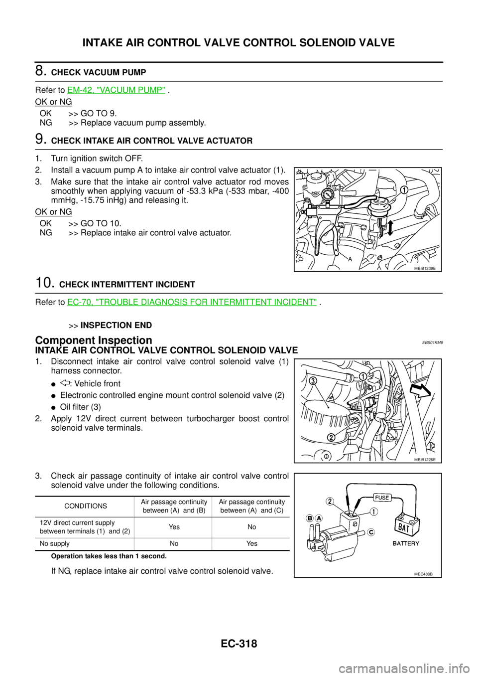
2. Install a vacuum pump A to intake air control valve actuator (1).
3. Make sure that the intake air control valve actuator rod moves
smoothly when applying vacuum of -53.3 kPa (-533 mbar, -400
mmHg, -15.75 inHg) and releasing it.
OK or NG
OK >> GO TO 10.
NG >> Replace intake air control valve actuator.
10.CHECK INTERMITTENT INCIDENT
Refer toEC-70, "
TROUBLE DIAGNOSIS FOR INTERMITTENT INCIDENT".
>>INSPECTION END
Component InspectionEBS01KM9
INTAKE AIR CONTROL VALVE CONTROL SOLENOID VALVE
1. Disconnect intake air control valve control solenoid valve (1)
harness connector.
l: Vehicle front
lElectronic controlled engine mount control solenoid valve (2)
lOil filter (3)
2. Apply 12V direct current between turbocharger boost control
solenoid valve terminals.
3. Check air passage continuity of intake air control valve control
solenoid valve under the following conditions.
Operation takes less than 1 second.
If NG, replace intake air control valve control solenoid valve.
MBIB1239E
MBIB1226E
CONDITIONSAir passage continuity
between (A) and (B)Air passage continuity
between (A) and (C)
12V direct current supply
between terminals (1) and (2)Ye s N o
No supply No Yes
MEC488B
Page 1419 of 3171
OIL PAN AND OIL STRAINER
EM-37
C
D
E
F
G
H
I
J
K
L
MA
EM
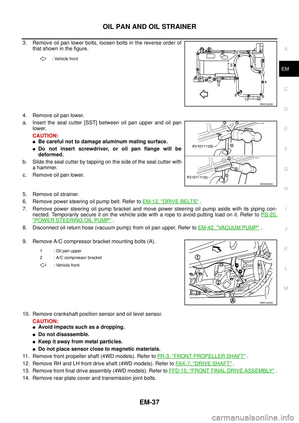
3. Remove oil pan lower bolts, loosen bolts in the reverse order of
that shown in the figure.
4. Remove oil pan lower.
a. Insert the seal cutter [SST] between oil pan upper and oil pan
lower.
CAUTION:
lBe careful not to damage aluminum mating surface.
lDo not insert screwdriver, or oil pan flange will be
deformed.
b. Slide the seal cutter by tapping on the side of the seal cutter with
a hammer.
c. Remove oil pan lower.
5. Remove oil strainer.
6. Remove power steering oil pump belt. Refer toEM-12, "
DRIVE BELTS".
7. Remove power steering oil pump bracket and move power steering oil pump aside with its piping con-
nected. Temporarily secure it on the vehicle side with a rope to avoid putting load on it. Refer toPS-25,
"POWER STEERING OIL PUMP".
8. Disconnect oil return hose (vacuum pump) from oil pan upper. Refer toEM-42, "
VACUUM PUMP".
9. Remove A/C compressor bracket mounting bolts (A).
10. Remove crankshaft position sensor and oil level sensor.
CAUTION:
lAvoid impacts such as a dropping.
lDo not disassemble.
lKeep it away from metal particles.
lDo not place sensor close to magnetic materials.
11. Remove front propeller shaft (4WD models). Refer toPR-3, "
FRONT PROPELLER SHAFT".
12. Remove RH and LH front drive shaft (4WD models). Refer toFAX-7, "
DRIVE SHAFT".
13. Remove front final drive assembly (4WD models). Refer toFFD-15, "
FRONT FINAL DRIVE ASSEMBLY".
14. Remove rear plate cover and transmission joint bolts.
: Vehicle front
PBIC3425E
SEM365EA
1 : Oil pan upper
2 : A/C compressor bracket
: Vehicle front
PBIC3426E
Page 1424 of 3171
EM-42
VACUUM PUMP
VACUUM PUMP
PFP:41920
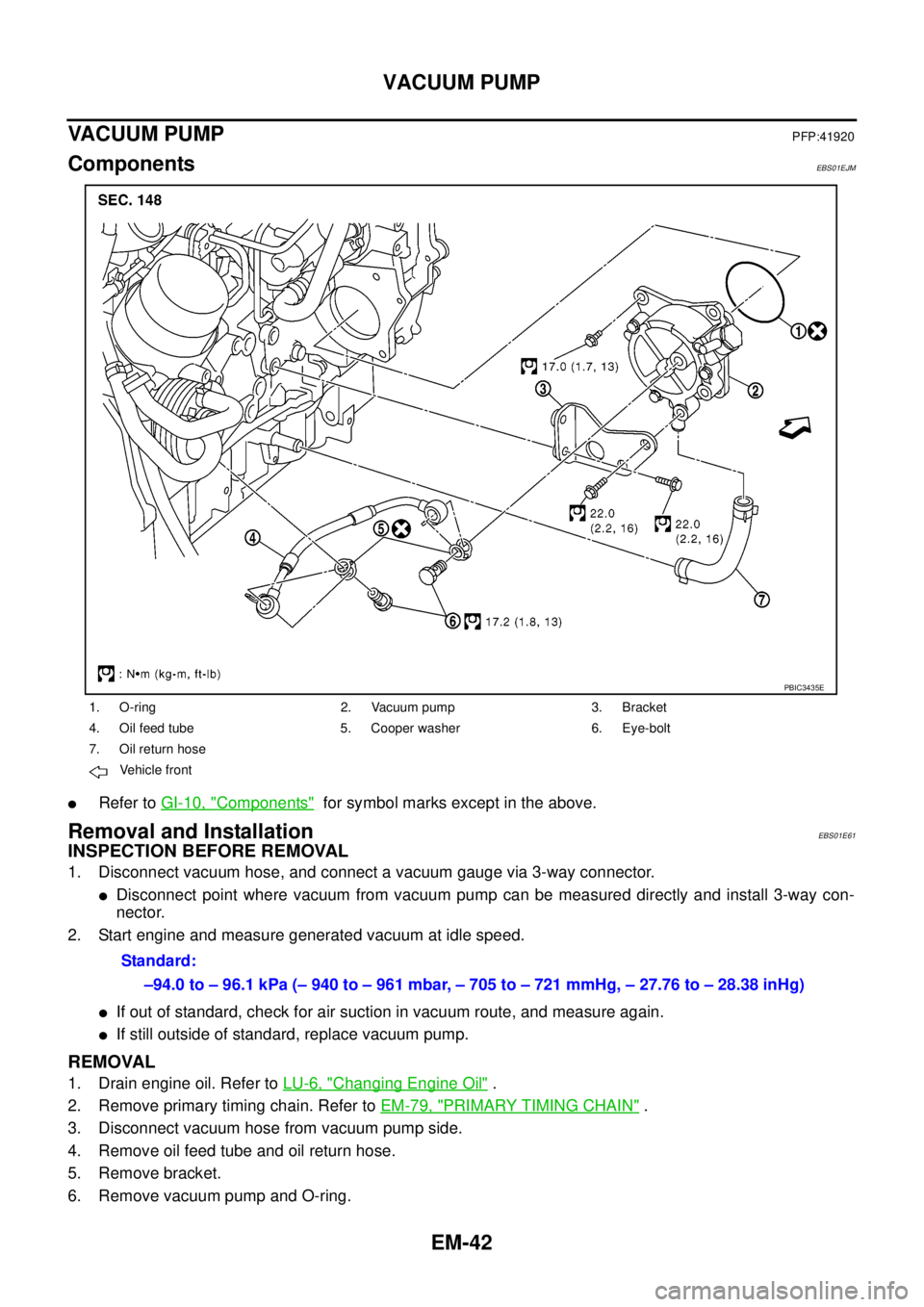
ComponentsEBS01EJM
lRefer toGI-10, "Components"for symbol marks except in the above.
Removal and InstallationEBS01E61
INSPECTION BEFORE REMOVAL
1. Disconnect vacuum hose, and connect a vacuum gauge via 3-way connector.
lDisconnect point where vacuum from vacuum pump can be measured directly and install 3-way con-
nector.
2. Start engine and measure generated vacuum at idle speed.
lIf out of standard, check for air suction in vacuum route, and measure again.
lIf still outside of standard, replace vacuum pump.
REMOVAL
1. Drain engine oil. Refer toLU-6, "Changing Engine Oil".
2. Remove primary timing chain. Refer toEM-79, "
PRIMARY TIMING CHAIN".
3. Disconnect vacuum hose from vacuum pump side.
4. Remove oil feed tube and oil return hose.
5. Remove bracket.
6. Remove vacuum pump and O-ring.
1. O-ring 2. Vacuum pump 3. Bracket
4. Oil feed tube 5. Cooper washer 6. Eye-bolt
7. Oil return hose
Vehicle front
PBIC3435E
Standard:
–94.0 to – 96.1 kPa (– 940 to – 961 mbar, – 705 to – 721 mmHg, – 27.76 to – 28.38 inHg)
Page 1465 of 3171
PRIMARY TIMING CHAIN
EM-83
C
D
E
F
G
H
I
J
K
L
MA
EM
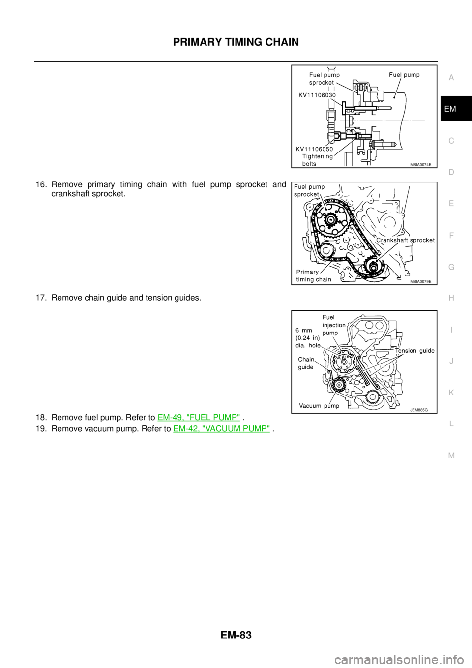
16. Remove primary timing chain with fuel pump sprocket and
crankshaft sprocket.
17. Remove chain guide and tension guides.
18. Remove fuel pump. Refer toEM-49, "
FUEL PUMP".
19. Remove vacuum pump. Refer toEM-42, "
VACUUM PUMP".
MBIA0074E
MBIA0079E
JEM885G
Page 1469 of 3171
PRIMARY TIMING CHAIN
EM-87
C
D
E
F
G
H
I
J
K
L
MA
EM
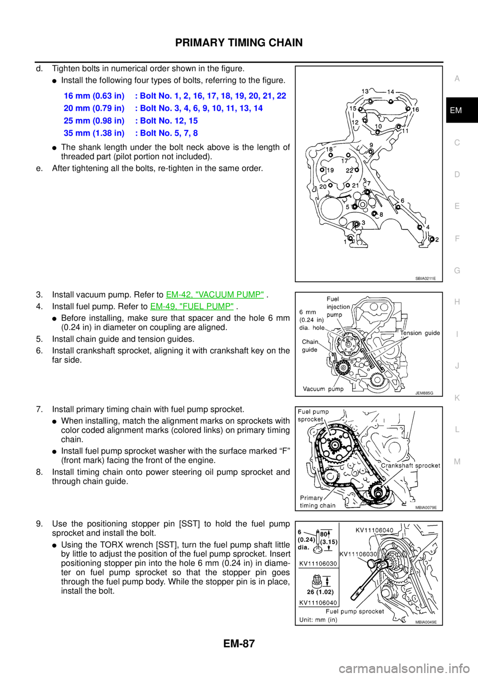
d. Tighten bolts in numerical order shown in the figure.
lInstall the following four types of bolts, referring to the figure.
lThe shank length under the bolt neck above is the length of
threaded part (pilot portion not included).
e. After tightening all the bolts, re-tighten in the same order.
3. Install vacuum pump. Refer toEM-42, "
VACUUM PUMP".
4. Install fuel pump. Refer toEM-49, "
FUEL PUMP".
lBefore installing, make sure that spacer and the hole 6 mm
(0.24 in) in diameter on coupling are aligned.
5. Install chain guide and tension guides.
6. Install crankshaft sprocket, aligning it with crankshaft key on the
far side.
7. Install primary timing chain with fuel pump sprocket.
lWhen installing, match the alignment marks on sprockets with
color coded alignment marks (colored links) on primary timing
chain.
lInstall fuel pump sprocket washer with the surface marked “F”
(front mark) facing the front of the engine.
8. Install timing chain onto power steering oil pump sprocket and
through chain guide.
9. Use the positioning stopper pin [SST] to hold the fuel pump
sprocket and install the bolt.
lUsing the TORX wrench [SST], turn the fuel pump shaft little
by little to adjust the position of the fuel pump sprocket. Insert
positioning stopper pin into the hole 6 mm (0.24 in) in diame-
ter on fuel pump sprocket so that the stopper pin goes
through the fuel pump body. While the stopper pin is in place,
install the bolt.16 mm (0.63 in) : Bolt No. 1, 2, 16, 17, 18, 19, 20, 21, 22
20mm(0.79in) :BoltNo.3,4,6,9,10,11,13,14
25 mm (0.98 in) : Bolt No. 12, 15
35 mm (1.38 in) : Bolt No. 5, 7, 8
SBIA0211E
JEM885G
MBIA0079E
MBIA0049E
Page 1494 of 3171
EM-112
CYLINDER BLOCK
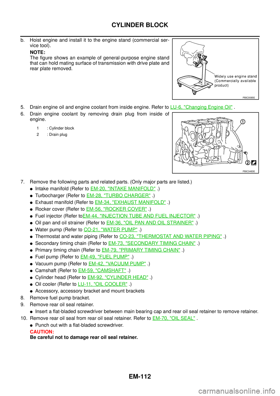
b. Hoist engine and install it to the engine stand (commercial ser-
vice tool).
NOTE:
The figure shows an example of general-purpose engine stand
that can hold mating surface of transmission with drive plate and
rear plate removed.
5. Drain engine oil and engine coolant from inside engine. Refer toLU-6, "
Changing Engine Oil".
6. Drain engine coolant by removing drain plug from inside of
engine.
7. Remove the following parts and related parts. (Only major parts are listed.)
lIntake manifold (Refer toEM-20, "INTAKE MANIFOLD".)
lTurbocharger (Refer toEM-28, "TURBO CHARGER".)
lExhaust manifold (Refer toEM-34, "EXHAUST MANIFOLD".)
lRocker cover (Refer toEM-56, "ROCKER COVER".)
lFuel injector (Refer toEM-44, "INJECTION TUBE AND FUEL INJECTOR".)
lOil pan and oil strainer (Refer toEM-36, "OIL PAN AND OIL STRAINER".)
lWater pump (Refer toCO-21, "WATER PUMP".)
lThermostat and water piping (Refer toCO-23, "THERMOSTAT AND WATER PIPING".)
lSecondary timing chain (Refer toEM-73, "SECONDARY TIMING CHAIN".)
lPrimary timing chain (Refer toEM-79, "PRIMARY TIMING CHAIN".)
lFuel pump (Refer toEM-49, "FUEL PUMP".)
lVacuum pump (Refer toEM-42, "VACUUM PUMP".)
lCamshaft (Refer toEM-59, "CAMSHAFT".)
lCylinder head (Refer toEM-92, "CYLINDER HEAD".)
lOil cooler (Refer toLU-11, "OIL COOLER".)
lAccessory, accessory bracket and mount brackets
8. Remove fuel pump bracket.
9. Remove rear oil seal retainer.
lInsert a flat-bladed screwdriver between main bearing cap and rear oil seal retainer to remove retainer.
10. Remove rear oil seal from rear oil seal retainer. Refer toEM-70, "
OIL SEAL".
lPunch out with a flat-bladed screwdriver.
CAUTION:
Be careful not to damage rear oil seal retainer.
PBIC0085E
1 : Cylinder block
2 : Drain plug
PBIC3483E
Page 1759 of 3171
IDX-7
A
C
D
E
F
G
H
I
J
K
L B
IDX
ALPHABETICAL INDEX
Starter ................................................................SC-27
Starting system ..................................................SC-27
Steering gear, linkage and transfer gear inspection .....
MA-36
,MA-37
Steering linkage .................................................PS-14
Steering wheel and column .................................PS-8
Step lamp .........................................................LT-145
Stop lamp .........................................................LT-121
Stop lamp switch .............................................EC-330
STOP/L - Wiring diagram .................................LT-121
Striking rod (M/T) ...............................................MT-23
Strut (front) ......................................................FSU-10
Sun roof, electric ................................................RF-10
Sunload sensor ..............................................ATC-112
Sunroof ..................................................RF-10,RF-21
Super lock ...........................................................BL-55
Supplemental Restraint System ........................SRS-6
Symbols and abbreviations .....................GI-10,GI-23
Symptom matrix chart ........................................EC-42
Synchronizer (M/T) ............................................MT-21
T
Tachometer ..........................................................DI-4
Tail lamp ...........................................................LT-125
TAIL/L - Wiring diagram ....................................LT-127
TC boost control solnoid valve ........................EC-309
TC boost sensor ..............................................EC-153
TCC/V - Wiring diagram ..................................EC-311
TCM circuit diagram ..........................................AT-42
TCM inspection table .........................................AT-76
Thermostat ........................................................CO-24
Three way catalyst precautions ............................GI-5
Throttle body ......................................................EM-20
Tie-rod ...............................................................PS-14
Timing chain .........................................EM-73,EM-79
Timing gear ........................................................EM-79
Tire rotation .......................................................MA-34
Tire size ..............................................................GI-60
Torque converter installation ...........................AT-250
Torque convertor clutch solenoid valveAT-110,AT-112
Tow truck towing .................................................GI-53
Towing point .......................................................GI-54
Transfer control device .............TF-74,TF-78,TF-105
Transfer control unit inspection table ..................TF-38
Transfer oil replacement ....................................MA-32
Transfer serial number .......................................GI-58
Transmission case (M/T) ...................................MT-19
Transmission serial number ....................GI-58,GI-59
Tread-FR&RR (Dimensions) ..............................GI-60
Trim .....................................................................EI-33
Trouble diagnoses ..............................................GI-11
Turbine revolution sensor ................................AT-123
Turbocharger .....................................................EM-28
Turbocharger charge air cooler .........................EM-18
Turbocharger precautions ....................................GI-6
TURN - Wiring diagram ....................................LT-100
Turn signal lamp .................................................LT-97
Two-pole lift ........................................................GI-52
V
Vacuum hose drawing (Engine control) .............EC-16
Vacuum pump ...................................................EM-42
Valve clearance ................................................EM-66
Valve guide .....................................................EM-101
Valve lifter .........................................................EM-62
Valve seat .......................................................EM-103
Valve spring ....................................................EM-104
Vanity mirror lamp .............................................LT-145
Vehicle identification number ..............................GI-57
Vehicle recovery (freeing a stuck vehicle) ..........GI-54
VEHSEC - Wiring diagram ...............................BL-143
Viscosity number (SAE) ....................................MA-15
W
Wait detection switch ..............................TF-63
,TF-66
WARN - Wiring diagram .....................................DI-30
Warning chime ....................................................DI-51
Warning lamps ....................................................DI-28
Washer, front .....................................................WW-4
Water pump ......................................................CO-21
Water temperature gauge .....................................DI-4
Wheel alignment (front) .....................................FSU-7
Wheel balance ..................................................MA-34
Wheel bearing (front) .........................................FAX-5
Wheel bearing (rear) .........................................RAX-6
Wheel sensors (ABS) .....................................BRC-37
Wheel size ..........................................................GI-60
Wheelbase (Dimensions) ....................................GI-60
Width (Dimensions) ............................................GI-60
WINDOW - Wiring diagram ...............................GW-20
Window, door ......................................GW-35,GW-38
Window, rear .....................................................GW-43
Windshield ........................................................GW-11
WIPER - Wiring diagram ..................................WW-12
Wiper, front ........................................................WW-4
Wiring Diagram (Cell code) list ..........................PG-68
Wiring diagrams ..................................................GI-15