2005 NISSAN NAVARA fuse box
[x] Cancel search: fuse boxPage 417 of 3171
![NISSAN NAVARA 2005 Repair Workshop Manual TROUBLE DIAGNOSIS
ATC-83
C
D
E
F
G
H
I
K
L
MA
B
AT C
1.CHECK FUSES
Check 15A fuses [No. 24 and 27, (located in the fuse and fusible link box)]. For fuse layout, refer toPG-84,
"FUSE AND FUSIBLE LINK B NISSAN NAVARA 2005 Repair Workshop Manual TROUBLE DIAGNOSIS
ATC-83
C
D
E
F
G
H
I
K
L
MA
B
AT C
1.CHECK FUSES
Check 15A fuses [No. 24 and 27, (located in the fuse and fusible link box)]. For fuse layout, refer toPG-84,
"FUSE AND FUSIBLE LINK B](/manual-img/5/57362/w960_57362-416.png)
TROUBLE DIAGNOSIS
ATC-83
C
D
E
F
G
H
I
K
L
MA
B
AT C
1.CHECK FUSES
Check 15A fuses [No. 24 and 27, (located in the fuse and fusible link box)]. For fuse layout, refer toPG-84,
"FUSE AND FUSIBLE LINK BOX".
OK or NG
OK >> GO TO 2.
NG >> GO TO 10.
2.CHECK BLOWER MOTOR POWER SUPPLY CIRCUIT
1. Turn ignition switch OFF.
2. Disconnect blower motor connector.
3. Turn ignition switch ON.
4. Turn the blower control dial to select any mode except off.
5. Check voltage between blower motor harness connector M94
terminal 2 and ground.
OK or NG
OK >> GO TO 12.
NG >> GO TO 3.
3.CHECK BLOWER MOTOR RELAY (SWITCH SIDE) POWER SUPPLY CIRCUIT
1. Turn ignition switch OFF.
2. Disconnect blower motor relay.
3. Check voltage between blower motor relay harness connector
E28 terminals 3 and 6 and ground.
OK or NG
OK >> GO TO 4.
NG >> Repair harness or connector.
4.CHECK BLOWER MOTOR RELAY
Refer toAT C - 8 6 , "
Blower Motor Relay".
OK or NG
OK >> GO TO 5.
NG >> Replace blower motor relay.
5.CHECK BLOWER MOTOR RELAY (SWITCH SIDE) CIRCUIT FOR OPEN
1. Turn ignition switch OFF.
2. Disconnect blower motor relay connector and blower motor con-
nector.
3. Check continuity between blower motor relay harness connector
E28 terminals 5 and 7 and blower motor harness connector M94
terminal 2.
OK or NG
OK >> GO TO 6.
NG >> Repair harness or connector.Fuses are good.
2 - Ground : Battery voltage.
MJIB0065E
3, 6 - Ground : Battery voltage.
MJIB0066E
5, 7 - 2 : Continuity should exist.
MJIB0067E
Page 605 of 3171
POWERDOORLOCKSYSTEM
BL-21
C
D
E
F
G
H
J
K
L
MA
B
BL
POWER DOOR LOCK SYSTEMPFP:24814
Component Parts and Harness Connector LocationEIS00D7Q
KING CAB
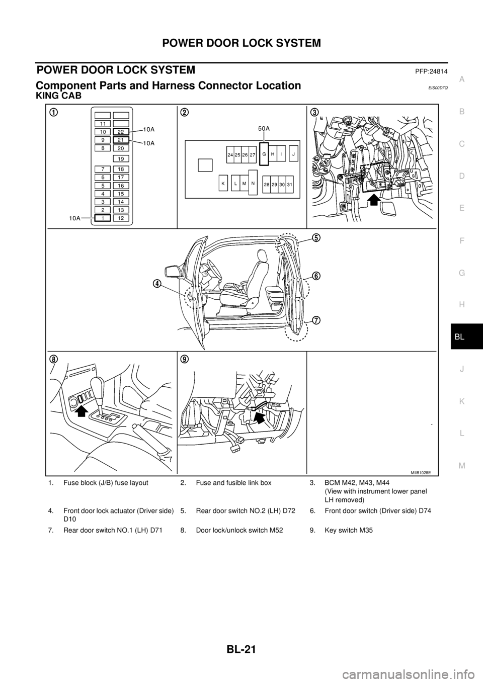
1. Fuse block (J/B) fuse layout 2. Fuse and fusible link box 3. BCM M42, M43, M44
(View with instrument lower panel
LH removed)
4. Front door lock actuator (Driver side)
D105. Rear door switch NO.2 (LH) D72 6. Front door switch (Driver side) D74
7. Rear door switch NO.1 (LH) D71 8. Door lock/unlock switch M52 9. Key switch M35
MIIB1028E
Page 606 of 3171
BL-22
POWER DOOR LOCK SYSTEM
DOUBLE CAB
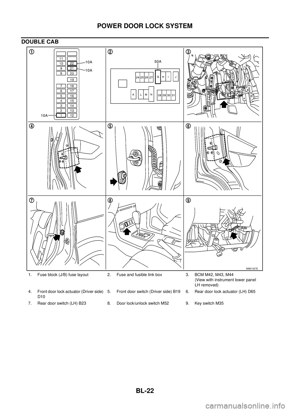
1. Fuse block (J/B) fuse layout 2. Fuse and fusible link box 3. BCM M42, M43, M44
(View with instrument lower panel
LH removed)
4. Front door lock actuator (Driver side)
D105. Front door switch (Driver side) B19 6. Rear door lock actuator (LH) D65
7. Rear door switch (LH) B23 8. Door lock/unlock switch M52 9. Key switch M35
MIIB1027E
Page 607 of 3171

POWERDOORLOCKSYSTEM
BL-23
C
D
E
F
G
H
J
K
L
MA
B
BL
System DescriptionEIS00D7R
Power is supplied at all times
lthrough 50A fusible link (letterG, located in the fuse and fusible link box)
lto BCM terminal 57
lthrough 10A fuse [No. 21, located in the fuse block (J/B)]
lto BCM terminal 41
lthrough 10A fuse [No. 22, located in the fuse block (J/B)]
lto key switch terminal 2.
When key switch is ON, power is supplied
lthrough key switch terminal 1
lto BCM terminal 5.
When ignition switch is in ON or START position
lthrough 10A fuse [No. 1, located in the fuse block (J/B)]
lto BCM terminal 3.
Ground is supplied
lto BCM terminal 55
lthrough body grounds M21, M80 and M83.
Door switch operation
When front door switch (driver side) is ON (door is OPEN), ground is supplied
lto BCM terminal 15
lthrough front door switch (driver side) terminal 2
lthrough front door switch (driver side) case ground.
When front door switch (passenger side) is ON (door is OPEN), ground is supplied
lto BCM terminal 14
lthrough front door switch (passenger side) terminal 2
lthrough front door switch (passenger side) case ground.
When rear door switch LH is ON (door is OPEN), ground is supplied (Double cab model)
lto BCM terminal 16
lthrough rear door switch LH terminal 2
lthrough rear door switch LH case ground.
When rear door switch RH is ON (door is OPEN), ground is supplied (Double cab model)
lto BCM terminal 12
lthrough rear door switch RH terminal 2
lthrough rear door switch RH case ground.
Key cylinder switch operation (Without multi-remote control system)
When key cylinder is turned to lock position, ground is supplied
lthrough BCM terminal 34
lto key cylinder switch (driver and passenger side) terminals 4
lthrough key cylinder switch (driver and passenger side) terminals 5
lthrough body ground M21, M80 and M83
then all doors are locked.
When key cylinder is turned to unlock position, ground is supplied
lthrough BCM terminal 32
lto key cylinder switch (driver and passenger side) terminal 6
lthrough key cylinder switch (driver and passenger side) terminal 5
lthrough body ground M21, M80 and M83
then all doors are unlocked.
Power door lock operation with door lock/unlock switch
When doors are lock by door lock/unlock switch, ground is supplied
Page 621 of 3171
POWERDOORLOCKSYSTEM
BL-37
C
D
E
F
G
H
J
K
L
MA
B
BL
Work FlowEIS00D81
1. Check the symptom and customer's requests.
2. Understand the outline of system. Refer toBL-23, "
System Description".
3. According to the trouble diagnosis, repair or replace the cause of the malfunction. Refer toBL-37, "
Trou-
ble Diagnoses Chart by Symptom".
4. Does power door lock system operate normally?
YES: GO TO 5.
NO:GOTO2.
5. INSPECTION END.
Trouble Diagnoses Chart by SymptomEIS00D82
NOTE:
Always check the “Work Flow” before troubleshooting. Refer toBL-37, "
Work Flow".
Check Power Supply and Ground CircuitEIS00D84
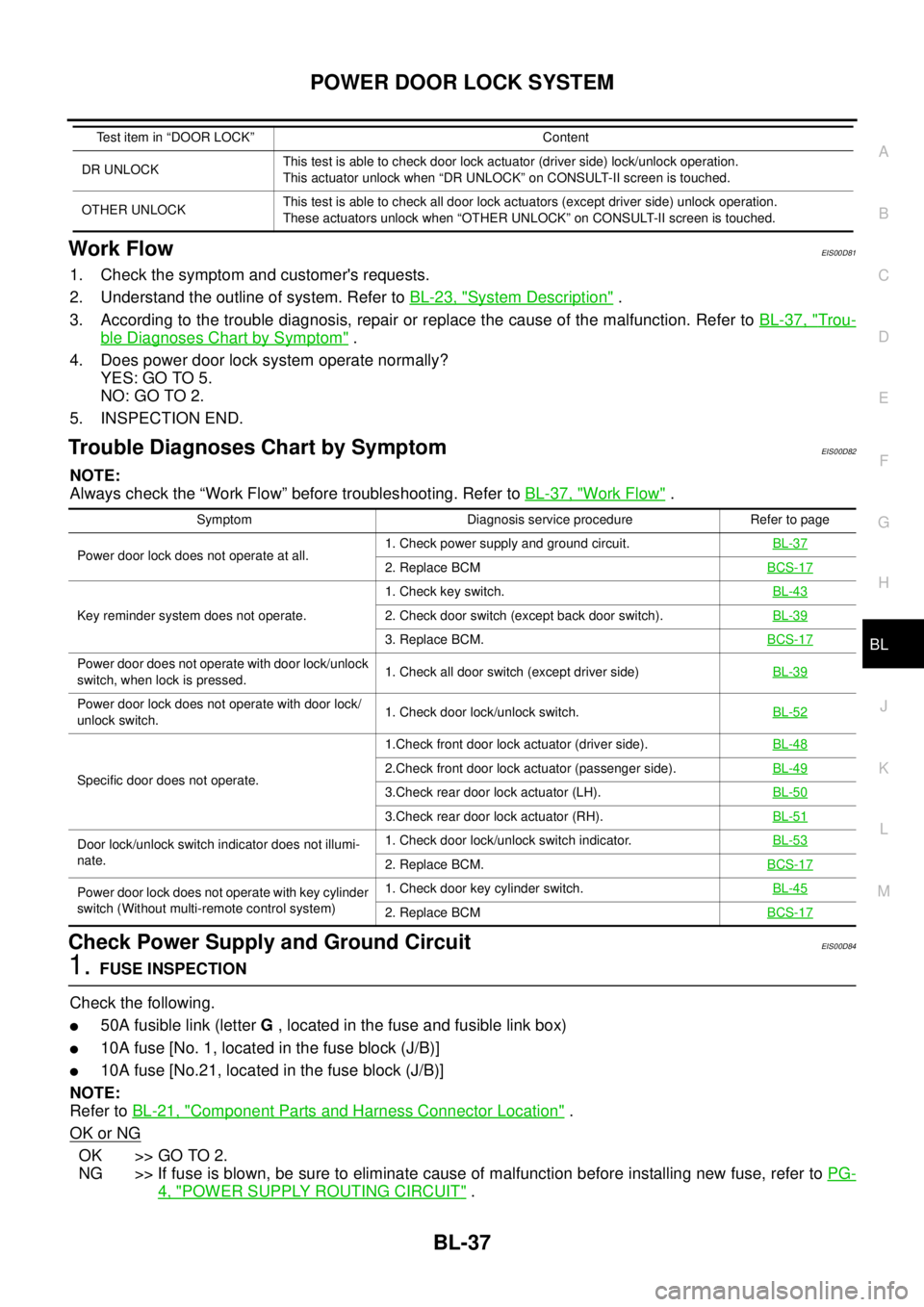
1.FUSE INSPECTION
Check the following.
l50A fusible link (letterG, located in the fuse and fusible link box)
l10A fuse [No. 1, located in the fuse block (J/B)]
l10A fuse [No.21, located in the fuse block (J/B)]
NOTE:
Refer toBL-21, "
Component Parts and Harness Connector Location".
OK or NG
OK >> GO TO 2.
NG >> If fuse is blown, be sure to eliminate cause of malfunction before installing new fuse, refer toPG-
4, "POWER SUPPLY ROUTING CIRCUIT".
DR UNLOCKThis test is able to check door lock actuator (driver side) lock/unlock operation.
This actuator unlock when “DR UNLOCK” on CONSULT-II screen is touched.
OTHER UNLOCKThis test is able to check all door lock actuators (except driver side) unlock operation.
These actuators unlock when “OTHER UNLOCK” on CONSULT-II screen is touched. Test item in “DOOR LOCK” Content
Symptom Diagnosis service procedure Refer to page
Power door lock does not operate at all.1. Check power supply and ground circuit.BL-37
2. Replace BCMBCS-17
Key reminder system does not operate.1. Check key switch.BL-432. Check door switch (except back door switch).BL-39
3. Replace BCM.BCS-17
Power door does not operate with door lock/unlock
switch, when lock is pressed.1. Check all door switch (except driver side)BL-39
Power door lock does not operate with door lock/
unlock switch.1. Check door lock/unlock switch.BL-52
Specific door does not operate.1.Check front door lock actuator (driver side).BL-482.Check front door lock actuator (passenger side).BL-49
3.Check rear door lock actuator (LH).BL-50
3.Check rear door lock actuator (RH).BL-51
Door lock/unlock switch indicator does not illumi-
nate.1. Check door lock/unlock switch indicator.BL-53
2. Replace BCM.BCS-17
Power door lock does not operate with key cylinder
switch (Without multi-remote control system)1. Check door key cylinder switch.BL-45
2. Replace BCMBCS-17
Page 639 of 3171
POWER DOOR LOCK — SUPER LOCK —
BL-55
C
D
E
F
G
H
J
K
L
MA
B
BL
POWER DOOR LOCK — SUPER LOCK —PFP:24814
Component Parts and Harness Connector LocationEIS00DWZ
KING CAB
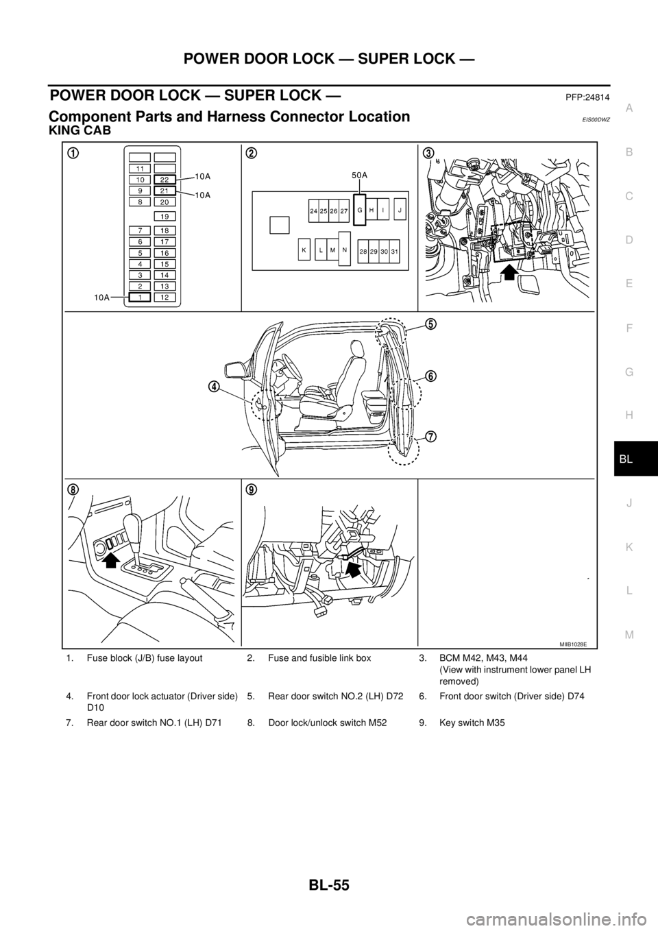
1. Fuse block (J/B) fuse layout 2. Fuse and fusible link box 3. BCM M42, M43, M44
(View with instrument lower panel LH
removed)
4. Front door lock actuator (Driver side)
D105. Rear door switch NO.2 (LH) D72 6. Front door switch (Driver side) D74
7. Rear door switch NO.1 (LH) D71 8. Door lock/unlock switch M52 9. Key switch M35
MIIB1028E
Page 640 of 3171
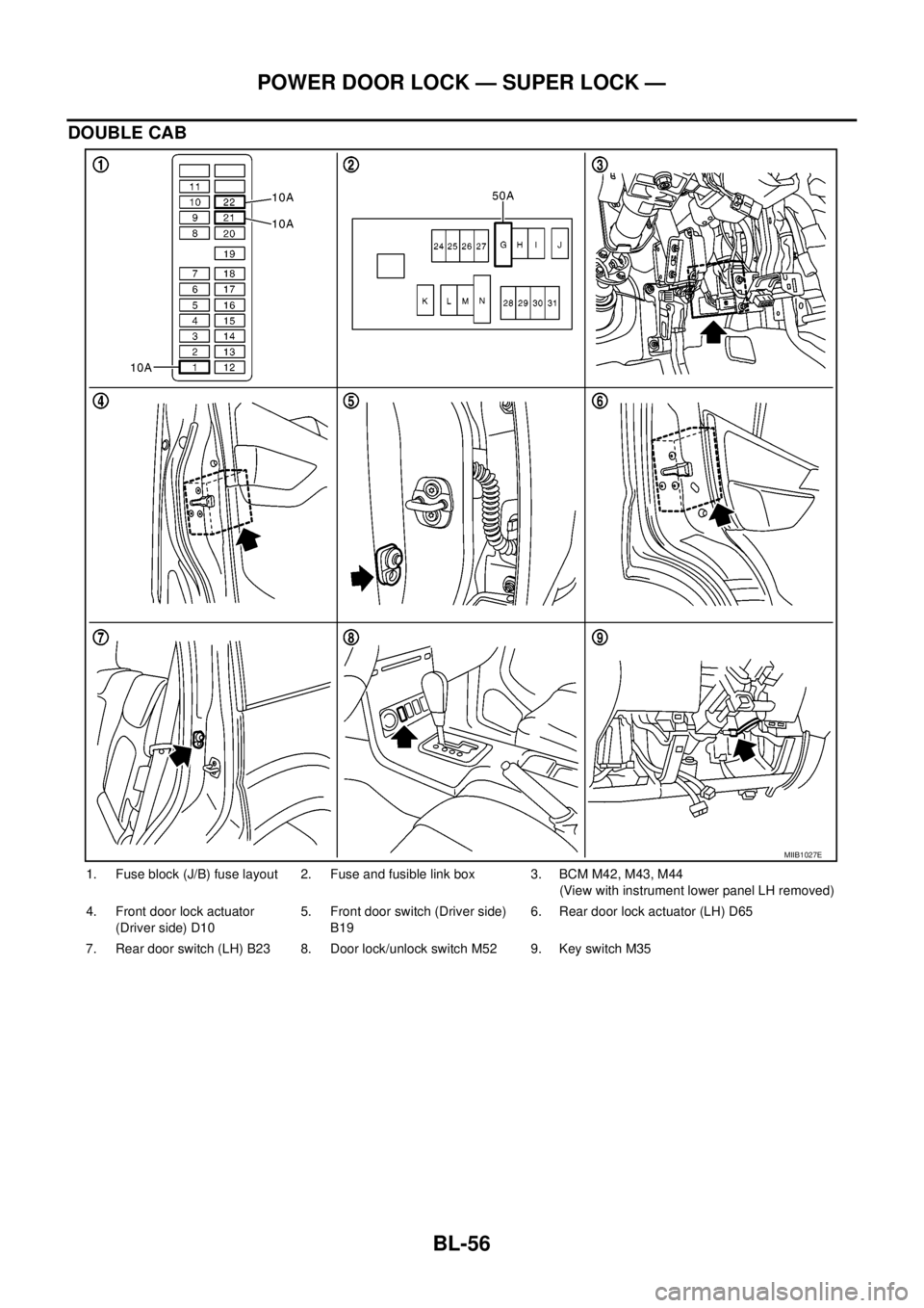
BL-56
POWER DOOR LOCK — SUPER LOCK —
DOUBLE CAB
1. Fuse block (J/B) fuse layout 2. Fuse and fusible link box 3. BCM M42, M43, M44
(View with instrument lower panel LH removed)
4. Front door lock actuator
(Driver side) D105. Front door switch (Driver side)
B196. Rear door lock actuator (LH) D65
7. Rear door switch (LH) B23 8. Door lock/unlock switch M52 9. Key switch M35
MIIB1027E
Page 641 of 3171

POWER DOOR LOCK — SUPER LOCK —
BL-57
C
D
E
F
G
H
J
K
L
MA
B
BL
System DescriptionEIS00DX0
Power is supplied at all times
lthrough 50A fusible link (letterG, located in the fuse and fusible link box)
lto BCM terminal 57
lthrough 10A fuse [No. 21, located in the fuse block (J/B)]
lto BCM terminal 41
lthrough 10A fuse [No. 22, located in the fuse block (J/B)]
lto key switch terminal 2.
When key switch is ON, power is supplied
lthrough key switch terminal 1
lto BCM terminal 5.
When ignition switch is in ON or START position
lthrough 10A fuse [No. 1, located in the fuse block (J/B)]
lto BCM terminal 3.
Ground is supplied
lto BCM terminal 55
lthrough body grounds M21, M80 and M83.
Door switch operation
When front door switch (driver side) is ON (door is OPEN), ground is supplied
lto BCM terminal 15
lthrough front door switch (driver side) terminal 2
lthrough front door switch (driver side) case ground.
When front door switch (passenger side) is ON (door is OPEN), ground is supplied
lto BCM terminal 14
lthrough front door switch (passenger side) terminal 2
lthrough front door switch (passenger side) case ground.
When rear door switch LH is ON (door is OPEN), ground is supplied (Double cab models)
lto BCM terminal 16
lthrough rear door switch LH terminal 2
lthrough rear door switch LH case ground.
When rear door switch RH is ON (door is OPEN), ground is supplied (Double cab models)
lto BCM terminal 12
lthrough rear door switch RH terminal 2
lthrough rear door switch RH case ground.
Super lock set/release operation
When super lock is set, ground is supplied
lThrough BCM terminals 59
lThrough each super lock actuators terminals 1 and 2
lTo BCM terminal 60
When super lock is released, ground is supplied
lThrough BCM terminal 60
lThrough each super lock actuators terminals 2 and 1
lTo BCM terminals 59
Power door lock operation with door lock/unlock switch
When doors are lock by door lock/unlock switch, ground is supplied
lto BCM terminal 34
lthrough door lock /unlock switch terminals 1 and 3
lthrough body grounds M21, M80 and M83.
then all doors are locked.