2005 NISSAN NAVARA fuse box
[x] Cancel search: fuse boxPage 2181 of 3171

LT-98
TURN SIGNAL AND HAZARD WARNING LAMPS
lto side turn signal lamp LH terminal 1 and
lto rear combination lamp LH terminal 2.
Ground is supplied
lto front combination lamp LH terminal 2
lto side turn signal lamp LH terminal 2 and
lto rear combination lamp LH terminal 3
lthrough ground E21, E41 and E61.
The BCM also supplies input to combination meter terminals 11 and 12 through the CAN communication. This
input is processed by unified meter control unit in combination meter, which in turn supplies ground to the left
turn signal indicator lamp.
With power and input supplied, BCM controls flashing of LH turn signal lamps.
RH Turn
When the turn signal switch is moved to the right position, BCM receives input signal requesting right turn sig-
nals to flash.
BCM then supplies power
lthrough BCM terminal 48
lto front combination lamp RH terminal 1
lto side turn signal lamp RH terminal 1 and
lto rear combination lamp RH terminal 2.
Ground is supplied
lto front combination lamp RH terminal 2
lto side turn signal lamp RH terminal 2 and
lto rear combination lamp RH terminal 3
lthrough ground E21, E41 and E61.
The BCM also supplies input to combination meter terminals 11 and 12 through the CAN communication. This
input is processed by unified meter control unit in combination meter, which in turn supplies ground to the right
turn signal indicator lamp.
With power and input supplied, BCM controls flashing of RH turn signal lamps.
HAZARD LAMP OPERATION
Power is supplied at all times
lthrough 50A fusible link (letter G, located in fuse and fusible link box)
lto BCM terminal 57,
lthrough 10A fuse [No. 19, located in fuse block (J/B)]
lto combination meter terminal 3.
Ground is supplied
lto BCM terminal 55 and
lto combination meter terminal 23
lthrough grounds M21, M80 and M83.
When the hazard switch is depressed, ground is supplied
lto BCM terminal 33
lthrough hazard switch terminal 2
lthrough hazard switch terminal 1
lthrough grounds M21, M80 and M83.
When the hazard switch is depressed, BCM receives input signal requesting turn signals to flash.
BCM then supplies power
lthrough BCM terminal 47
lto front combination lamp LH terminal 1
lto side turn signal lamp LH terminal 1 and
lto rear combination lamp LH terminal 2,
lthrough BCM terminal 48
Page 2208 of 3171
PARKING, LICENSE PLATE AND TAIL LAMPS
LT-125
C
D
E
F
G
H
I
J
L
MA
B
LT
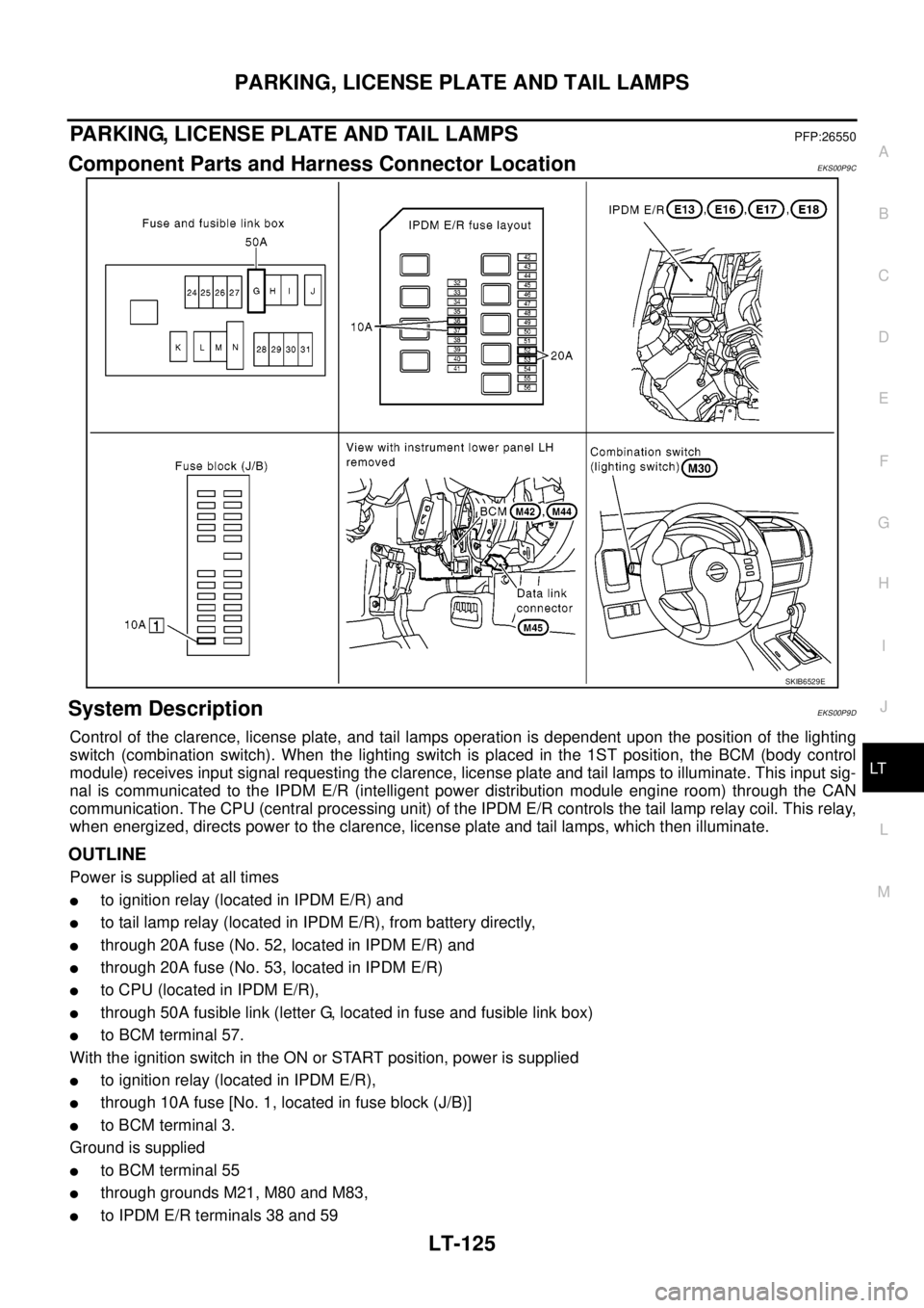
PARKING, LICENSE PLATE AND TAIL LAMPSPFP:26550
Component Parts and Harness Connector LocationEKS00P9C
System DescriptionEKS00P9D
Control of the clarence, license plate, and tail lamps operation is dependent upon the position of the lighting
switch (combination switch). When the lighting switch is placed in the 1ST position, the BCM (body control
module) receives input signal requesting the clarence, license plate and tail lamps to illuminate. This input sig-
nal is communicated to the IPDM E/R (intelligent power distribution module engine room) through the CAN
communication. The CPU (central processing unit) of the IPDM E/R controls the tail lamp relay coil. This relay,
when energized, directs power to the clarence, license plate and tail lamps, which then illuminate.
OUTLINE
Power is supplied at all times
lto ignition relay (located in IPDM E/R) and
lto tail lamp relay (located in IPDM E/R), from battery directly,
lthrough 20A fuse (No. 52, located in IPDM E/R) and
lthrough 20A fuse (No. 53, located in IPDM E/R)
lto CPU (located in IPDM E/R),
lthrough 50A fusible link (letter G, located in fuse and fusible link box)
lto BCM terminal 57.
With the ignition switch in the ON or START position, power is supplied
lto ignition relay (located in IPDM E/R),
lthrough 10A fuse [No. 1, located in fuse block (J/B)]
lto BCM terminal 3.
Ground is supplied
lto BCM terminal 55
lthrough grounds M21, M80 and M83,
lto IPDM E/R terminals 38 and 59
SKIB6529E
Page 2228 of 3171
INTERIOR ROOM LAMP
LT-145
C
D
E
F
G
H
I
J
L
MA
B
LT
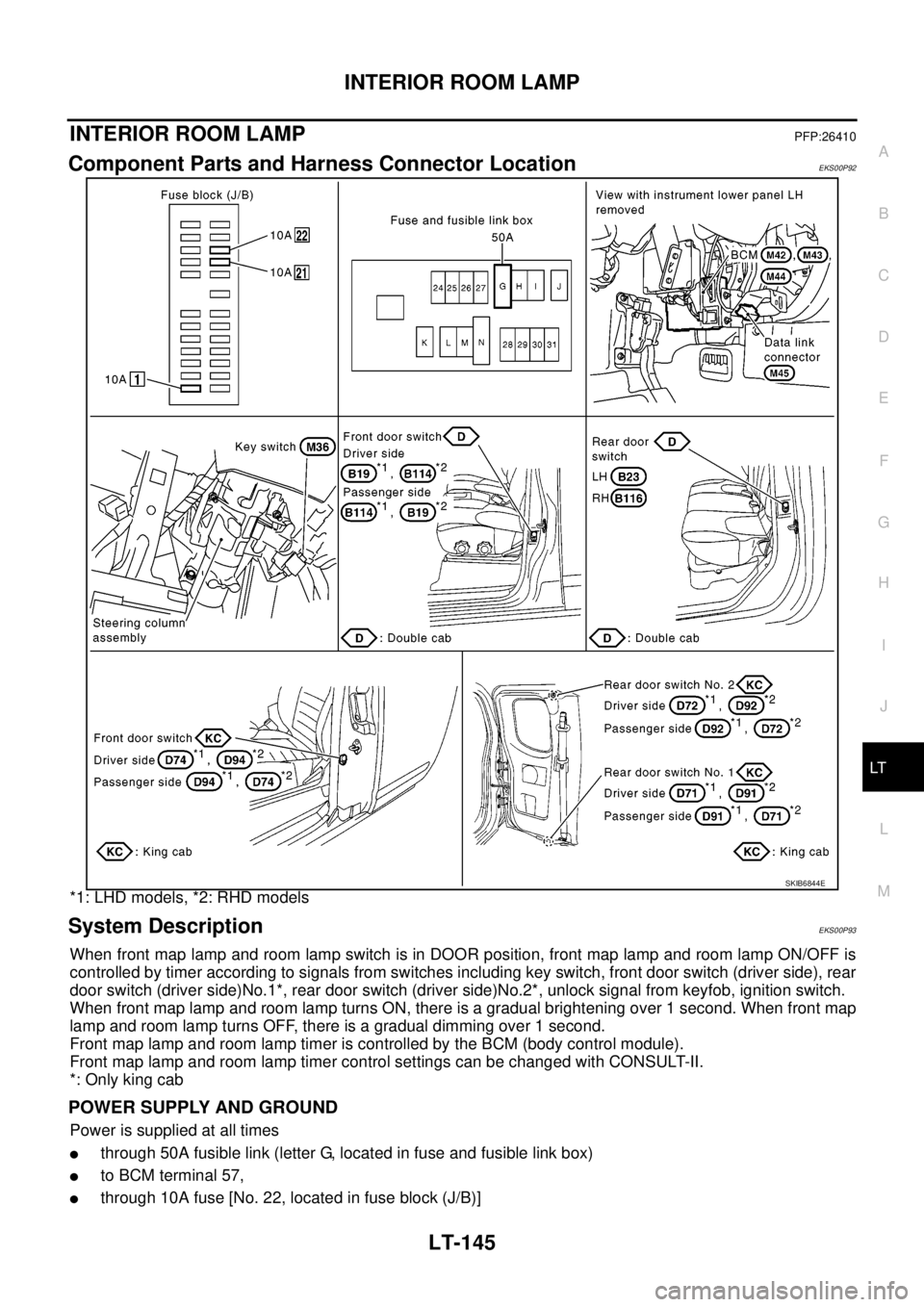
INTERIOR ROOM LAMPPFP:26410
Component Parts and Harness Connector LocationEKS00P92
*1: LHD models, *2: RHD models
System DescriptionEKS00P93
When front map lamp and room lamp switch is in DOOR position, front map lamp and room lamp ON/OFF is
controlled by timer according to signals from switches including key switch, front door switch (driver side), rear
door switch (driver side)No.1*, rear door switch (driver side)No.2*, unlock signal from keyfob, ignition switch.
When front map lamp and room lamp turns ON, there is a gradual brightening over 1 second. When front map
lamp and room lamp turns OFF, there is a gradual dimming over 1 second.
Front map lamp and room lamp timer is controlled by the BCM (body control module).
Front map lamp and room lamp timer control settings can be changed with CONSULT-II.
*: Only king cab
POWER SUPPLY AND GROUND
Power is supplied at all times
lthrough 50A fusible link (letter G, located in fuse and fusible link box)
lto BCM terminal 57,
lthrough 10A fuse [No. 22, located in fuse block (J/B)]
SKIB6844E
Page 2245 of 3171

LT-162
ILLUMINATION
ILLUMINATION
PFP:27545
System DescriptionEKS00P8V
Control of the illumination lamps operation is dependent upon the position of the lighting switch (combination
switch). When the lighting switch is placed in the 1ST position, 2ND position or AUTO position (headlamp is
ON) the BCM (body control module) receives input signal requesting the illumination lamps to illuminate. This
input signal is communicated to the IPDM E/R (intelligent power distribution module engine room) through the
CAN communication. The CPU (central processing unit) of the IPDM E/R controls the tail lamp relay coil. This
relay, when energized, directs power to the illumination lamps, which then illuminate.
Power is supplied at all times
lto ignition relay (located in IPDM E/R) and
lto tail lamp relay (located in IPDM E/R), from battery directly,
lthrough 50A fusible link (letter G, located in fuse and fusible link box)
lto BCM terminal 57,
lthrough 20A fuse (No. 52, located in IPDM E/R) and
lthrough 20A fuse (No. 53, located in IPDM E/R)
lto CPU (located in IPDM E/R),
lthrough 10A fuse [No.19, located in fuse block (J/B)]
lto combination meter terminal 3.
With the ignition switch in the ON or START position, power is supplied
lto ignition relay (located in IPDM E/R),
lthrough 10A fuse [No. 1, located in fuse block (J/B)]
lto BCM terminal 3,
lthrough 10A fuse [No. 14, located in fuse block (J/B)]
lto combination meter 16.
Ground is supplied
lto BCM terminal 55 and
lto combination meter terminal 23
lthrough grounds M21, M80 and M83,
lto IPDM E/R terminals 38 and 59
lthrough grounds E21, E41 and E61.
ILLUMINATION OPERATION BY LIGHTING SWITCH
With the lighting switch in the 1ST position, 2ND position or AUTO position (headlamp is ON), the BCM
receives input signal requesting the illumination lamps to illuminate. This input signal is communicated to the
IPDM E/R through the CAN communication. The CPU of the IPDM E/R controls the tail lamp relay coil, which,
when energized, directs power
lthrough 10A fuse (No. 37, located in IPDM E/R)
lthrough IPDM E/R terminal 57
lto hazard switch (illumination) terminal 3
lto 4WD shift switch (illumination) terminal 7 (with 4-wheel drive)
lto front air control (illumination) terminal 8
lto audio unit (illumination) terminal 2 (1CD player)
lto audio unit (illumination) terminal 8 (6CD player)
lto AV switch (illumination) terminal 3 (with NAVI)
lto audio unit (illumination) terminal 29 (with NAVI)
lto glove box lamp terminal 1
lto A/T device (illumination) terminal 3 (with A/T)
lto heat up switch (illumination) terminal 5
lto DIFF LOCK switch (illumination) terminal 4 (with DIFF LOCK)
lto heated seat switch (driver side) (illumination) terminal 5 (with heated seats)
lto heated seat switch (passenger side) (illumination) terminal 5 (with heated seats)
Page 2280 of 3171
DESCRIPTION
MA-5
C
D
E
F
G
H
I
J
K
MA
B
MA
DESCRIPTIONPFP:00000
Pre-Delivery Inspection ItemsELS001K2
Shown below are Pre-delivery Inspection Items required for the new vehicle. It is recommended that
necessary items other than those listed here be added, paying due regard to the conditions in each
country.
Perform applicable items on each model. Consult text of this section for specifications.
Install vehicle protection kit
Fit all accessories ordered (if applicable) (e.g. towbar, audio, navigation, air conditioner, styling kit)
UNDER HOOD — engine off
Check coolant level and cooling system for leaks
Charge battery and check terminals for condition
Check drive belts tension
Check fuel filter for water or dust (diesel only) and fuel system for leaks
Check engine oil level and for oil leaks
Check brake and clutch fluid levels and fluid lines for leaks
Check and top up washer reservoirs
Check power steering fluid level and fluid lines for leaks (if applicable)
Check air conditioning system for gas leaks (if applicable)
ON INSIDE AND OUTSIDE
Install transit fuse if removed for vehicle storage
Check instruments, gauges, lamps, horn and accessories for operation
Check wipers and washers for operation and adjustment
Check interior and door mirrors and sun visors for operation
Set radio code and set clock
Check parking brake adjustment
Check clutch pedal adjustment
Check steering lock operation
Check seat adjusters and seat belts for operation
Check all windows for operation and alignment
Check mouldings, trim and fittings for fit and alignment
Check weatherstrips for fit and adhesion
Check hood, trunk lid, door panels and fuel lid for fit and alignment
Check latches, keys, remote key, door locks and remote trunk lid and fuel lid release for operation
Check wheel nut torques
Check tyre pressure (incl. spare tyre)
Check tool kit and jack for operation
Check automatic transmission/transaxle starter inhibitor (if applicable)
Check sunroof for operation and alignment (if applicable)
UNDER BODY
Check manual transmission/transaxle, differential and transfer box for oil level and oil leaks
Tighten bolts and nuts steering linkage and gear box, axle/suspension parts, propeller and exhaust system
Check brake and clutch lines, and oil/fluid reservoirs for leaks
Remove front suspension spacer blocks (if applicable)
Check body mounting torque (if applicable)
Page 2460 of 3171
TROUBLE DIAGNOSIS
MTC-73
C
D
E
F
G
H
I
K
L
MA
B
MTC
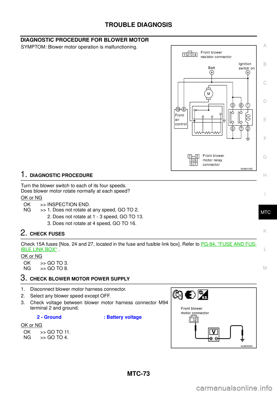
DIAGNOSTIC PROCEDURE FOR BLOWER MOTOR
SYMPTOM: Blower motor operation is malfunctioning.
1.DIAGNOSTIC PROCEDURE
Turntheblowerswitchtoeachofitsfourspeeds.
Does blower motor rotate normally at each speed?
OK or NG
OK >> INSPECTION END.
NG >> 1. Does not rotate at any speed, GO TO 2.
2. Does not rotate at 1 - 3 speed, GO TO 13.
3. Does not rotate at 4 speed, GO TO 16.
2.CHECK FUSES
Check 15A fuses [Nos. 24 and 27, located in the fuse and fusible link box]. Refer toPG-84, "
FUSE AND FUS-
IBLE LINK BOX".
OK or NG
OK >> GO TO 3.
NG >> GO TO 8.
3.CHECK BLOWER MOTOR POWER SUPPLY
1. Disconnect blower motor harness connector.
2. Select any blower speed except OFF.
3. Check voltage between blower motor harness connector M94
terminal 2 and ground.
OK or NG
OK >> GO TO 11.
NG >> GO TO 4.
MJIB0105E
2 - Ground : Battery voltage
MJIB0065E
Page 2461 of 3171
MTC-74
TROUBLE DIAGNOSIS
4.CHECK BLOWER MOTOR RELAY
Refer toMTC-77, "
Blower Motor Relay".
OK or NG
OK >> GO TO 5.
NG >> Replace blower motor relay.
5.CHECK BLOWER MOTOR POWER FROM RELAY TO BLOWER MOTOR
1. Reconnect blower motor harness connector.
2. Disconnect blower motor relay.
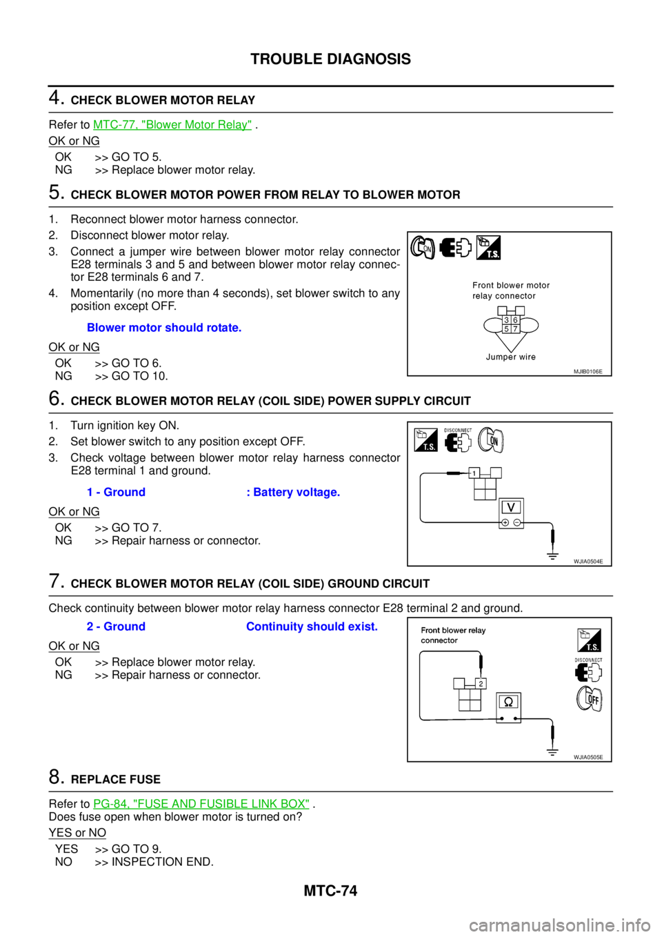
3. Connect a jumper wire between blower motor relay connector
E28 terminals 3 and 5 and between blower motor relay connec-
tor E28 terminals 6 and 7.
4. Momentarily (no more than 4 seconds), set blower switch to any
position except OFF.
OK or NG
OK >> GO TO 6.
NG >> GO TO 10.
6.CHECK BLOWER MOTOR RELAY (COIL SIDE) POWER SUPPLY CIRCUIT
1. Turn ignition key ON.
2. Set blower switch to any position except OFF.
3. Check voltage between blower motor relay harness connector
E28 terminal 1 and ground.
OK or NG
OK >> GO TO 7.
NG >> Repair harness or connector.
7.CHECK BLOWER MOTOR RELAY (COIL SIDE) GROUND CIRCUIT
Check continuity between blower motor relay harness connector E28 terminal 2 and ground.
OK or NG
OK >> Replace blower motor relay.
NG >> Repair harness or connector.
8.REPLACE FUSE
Refer toPG-84, "
FUSE AND FUSIBLE LINK BOX".
Does fuse open when blower motor is turned on?
YESorNO
YES >> GO TO 9.
NO >> INSPECTION END.Blower motor should rotate.
MJIB0106E
1 - Ground : Battery voltage.
WJIA0504E
2 - Ground Continuity should exist.
WJIA0505E
Page 2531 of 3171

PG-2
REAR DOOR LH HARNESS/KING CAB MOD-
ELS ...................................................................... 66
REAR DOOR RH HARNESS/KING CAB MOD-
ELS ...................................................................... 66
TAIL HARNESS ................................................... 67
Wiring Diagram Codes (Cell Codes) ....................... 68
ELECTRICAL UNITS LOCATION ............................. 71
Electrical Units Location ......................................... 71
ENGINE COMPARTMENT .................................. 71
PASSENGER COMPARTMENT .......................... 72
Fuse ........................................................................ 74
Fusible Link ............................................................ 74
Circuit Breaker (Built Into BCM) ............................. 74
HARNESS CONNECTOR ......................................... 75
Description .............................................................. 75
HARNESS CONNECTOR (TAB-LOCKING
TYPE) .................................................................. 75
HARNESS CONNECTOR (SLIDE-LOCKINGTYPE) .................................................................. 76
HARNESS CONNECTOR (DIRECT-CONNECT
SRS COMPONENT TYPE) .................................. 77
ELECTRICAL UNITS ................................................ 78
Terminal Arrangement ............................................. 78
STANDARDIZED RELAY .......................................... 79
Description .............................................................. 79
NORMAL OPEN, NORMAL CLOSED AND
MIXED TYPE RELAYS ........................................ 79
TYPE OF STANDARDIZED RELAYS .................. 79
SUPER MULTIPLE JUNCTION (SMJ) ...................... 81
Terminal Arrangement ............................................. 81
FUSE BLOCK - JUNCTION BOX (J/B) .................... 83
Terminal Arrangement ............................................. 83
FUSE AND FUSIBLE LINK BOX .............................. 84
Terminal Arrangement ............................................. 84
FUSE AND RELAY BOX ........................................... 85
Terminal Arrangement ............................................. 85