2005 NISSAN NAVARA tire size
[x] Cancel search: tire sizePage 60 of 3171

AT-52
TROUBLE DIAGNOSIS
Vehicle Speed at Which Gear Shifting Occurs
ECS00FX6
2WD MODELS
lAt half throttle, the accelerator opening is 4/8 of the full opening.
4WD MODELS
lAt half throttle, the accelerator opening is 4/8 of the full opening.
Vehicle Speed at Which Lock-up Occurs/ReleasesECS00FX7
2WD MODELS
lAt closed throttle, the accelerator opening is less than 1/8 condition. (Closed throttle position signal: OFF)
lAt half throttle, the accelerator opening is 4/8 of the full opening.
4WD MODELS
lAt closed throttle, the accelerator opening is less than 1/8 condition. (Closed throttle position signal: OFF)
lAt half throttle, the accelerator opening is 4/8 of the full opening.Tire sizeThrottle
positionVehicle speed [km/h (MPH)]
D
1®D2D2®D3D3®D4D4®D5D5®D4D4®D3D3®D2D2®D1
255/65 R17
255/70 R16Full
throttle41 - 45
(25 - 28)66 - 72
(41 - 45)103 - 113
(64 - 70)148 - 164
(92 - 102)144 - 160
(89 - 99)92 - 102
(57 - 63)53 - 59
(33 - 37)23 - 24
(14 - 15)
Half
throttle34 - 38
(21 - 24)55 - 61
(34 - 38)86 - 96
(53 - 60)118 - 130
(73 - 81)88 - 98
(55 - 61)60 - 66
(37 - 41)39 - 43
(24 - 27)10 - 11
(6 - 7)
Tire sizeThrottle
positionVehiclespeed [km/h(MPH)]
D1®D2D2®D3D3®D4D4®D5D5®D4D4®D3D3®D2D2®D1
255/65 R17
255/70 R16Full
throttle38 - 42
(24 - 26)62 - 68
(39 - 42)97 - 107
(60 - 66)141 - 155
(88 - 96)137 - 151
(85 - 94)87 - 97
(54 - 60)50 - 56
(31 - 35)22 - 24
(14 - 15)
Half
throttle32 - 36
(20 - 22)52 - 58
(32 - 36)82 - 90
(51 - 56)117 - 129
(73 - 80)83 - 91
(52 - 57)57 - 63
(35 - 39)37 - 41
(23 - 25)10 - 11
(6 - 7)
265/70 R16LTFull
throttle40 - 44
(25 - 27)65 - 71
(40 - 44)101 - 111
(63 - 69)145 - 161
(90 - 100)142 - 156
(88 - 97)90 - 100
(56 - 62)52 - 58
(32 - 36)23 - 25
(14 - 16)
Half
throttle33 - 37
(21 - 23)54 - 60
(34 - 37)85 - 93
(53 - 58)121 - 133
(75 - 83)85 - 95
(53 - 59)59 - 65
(37 - 40)38 - 42
(24 - 26)10 - 11
(6 - 7)
Tire size Throttle positionVehicle speed [km/h (MPH)]
Lock-up ON Lock-up OFF
255/65 R17
255/70 R16Closed throttle 73 - 81 (45 - 50) 70 - 78 (44 - 48)
Half throttle 141 - 155 (88 - 96) 130 - 144 (81 - 89)
Tire size Throttle positionVehicle speed [km/h (MPH)]
Lock-up ON Lock-up OFF
255/65 R17
255/70 R16Closed throttle 69 - 77 (43 - 48) 66 - 74 (41 - 46)
Half throttle 134 - 148 (83 - 92) 123 - 137 (76 - 85)
265/70 R16LTClosed throttle 72 - 80 (45 - 50) 69 - 77 (43 - 48)
Half throttle 139 - 153 (86 - 95) 128 - 142 (80 - 88)
Page 332 of 3171

AT-324
SERVICE DATA AND SPECIFICATIONS (SDS)
Vehicle Speed at Which Gear Shifting Occurs
ECS00H8W
2WD MODELS
lAt half throttle, the accelerator opening is 4/8 of the full opening.
4WD MODELS
lAt half throttle, the accelerator opening is 4/8 of the full opening.
Vehicle Speed at Which Lock-Up Occurs/ReleasesECS00H8X
2WD MODELS
lAt closed throttle, the accelerator opening is less than 1/8 condition. (Closed throttle position signal: OFF)
lAt half throttle, the accelerator opening is 4/8 of the full opening.
4WD MODELS
lAt closed throttle, the accelerator opening is less than 1/8 condition. (Closed throttle position signal: OFF)
lAt half throttle, the accelerator opening is 4/8 of the full opening.
A/T Fluid Temperature SensorECS00G3T
Tire sizeThrottle
positionVehicle speed [km/h (MPH)]
D1®D2D2®D3D3®D4D4®D5D5®D4D4®D3D3®D2D2®D1
255/65 R17
255/70 R16Full
throttle41 - 45
(25 - 28)66 - 72
(41 - 45)103 - 113
(64 - 70)148 - 164
(92 - 102)144 - 160
(89 - 99)92 - 102
(57 - 63)53 - 59
(33 - 37)23 - 24
(14 - 15)
Half
throttle34 - 38
(21 - 24)55 - 61
(34 - 38)86 - 96
(53 - 60)118 - 130
(73 - 81)88 - 98
(55 - 61)60 - 66
(37 - 41)39 - 43
(24 - 27)10 - 11
(6 - 7)
Tire sizeThrottle
positionVehiclespeed [km/h(MPH)]
D1®D2D2®D3D3®D4D4®D5D5®D4D4®D3D3®D2D2®D1
255/65 R17
255/70 R16Full
throttle38 - 42
(24 - 26)62 - 68
(39 - 42)97 - 107
(60 - 66)141 - 155
(88 - 96)137 - 151
(85 - 94)87 - 97
(54 - 60)50 - 56
(31 - 35)22 - 24
(14 - 15)
Half
throttle32 - 36
(20 - 22)52 - 58
(32 - 36)82 - 90
(51 - 56)117 - 129
(73 - 80)83 - 91
(52 - 57)57 - 63
(35 - 39)37 - 41
(23 - 25)10 - 11
(6 - 7)
265/70 R16LTFull
throttle40 - 44
(25 - 27)65 - 71
(40 - 44)101 - 111
(63 - 69)145 - 161
(90 - 100)142 - 156
(88 - 97)90 - 100
(56 - 62)52 - 58
(32 - 36)23 - 25
(14 - 16)
Half
throttle33 - 37
(21 - 23)54 - 60
(34 - 37)85 - 93
(53 - 58)121 - 133
(75 - 83)85 - 95
(53 - 59)59 - 65
(37 - 40)38 - 42
(24 - 26)10 - 11
(6 - 7)
Tire size Throttle positionVehicle speed [km/h (MPH)]
Lock-up ON Lock-up OFF
255/65 R17
255/70 R16Closed throttle 73 - 81 (45 - 50) 70 - 78 (44 - 48)
Half throttle 141 - 155 (88 - 96) 130 - 144 (81 - 89)
Tire size Throttle positionVehicle speed [km/h (MPH)]
Lock-up ON Lock-up OFF
255/65 R17
255/70 R16Closed throttle 69 - 77 (43 - 48) 66 - 74 (41 - 46)
Half throttle 134 - 148 (83 - 92) 123 - 137 (76 - 85)
265/70 R16LTClosed throttle 72 - 80 (45 - 50) 69 - 77 (43 - 48)
Half throttle 139 - 153 (86 - 95) 128 - 142 (80 - 88)
Name Condition CONSULT-II “DATA MONITOR” (Approx.) Resistance (Approx.)
ATFTEMPSE10°C(32°F) 3.3 V 15 kW
20°C(68°F) 2.7 V 6.5 kW
80°C(176°F) 0.9 V 0.9 kW
ATFTEMPSE20°C(32°F) 3.3 V 10 kW
20°C(68°F) 2.5V 4kW
80°C(176°F) 0.7 V 0.5 kW
Page 559 of 3171
TROUBLE DIAGNOSIS
AV-71
C
D
E
F
G
H
I
J
L
MA
B
AV
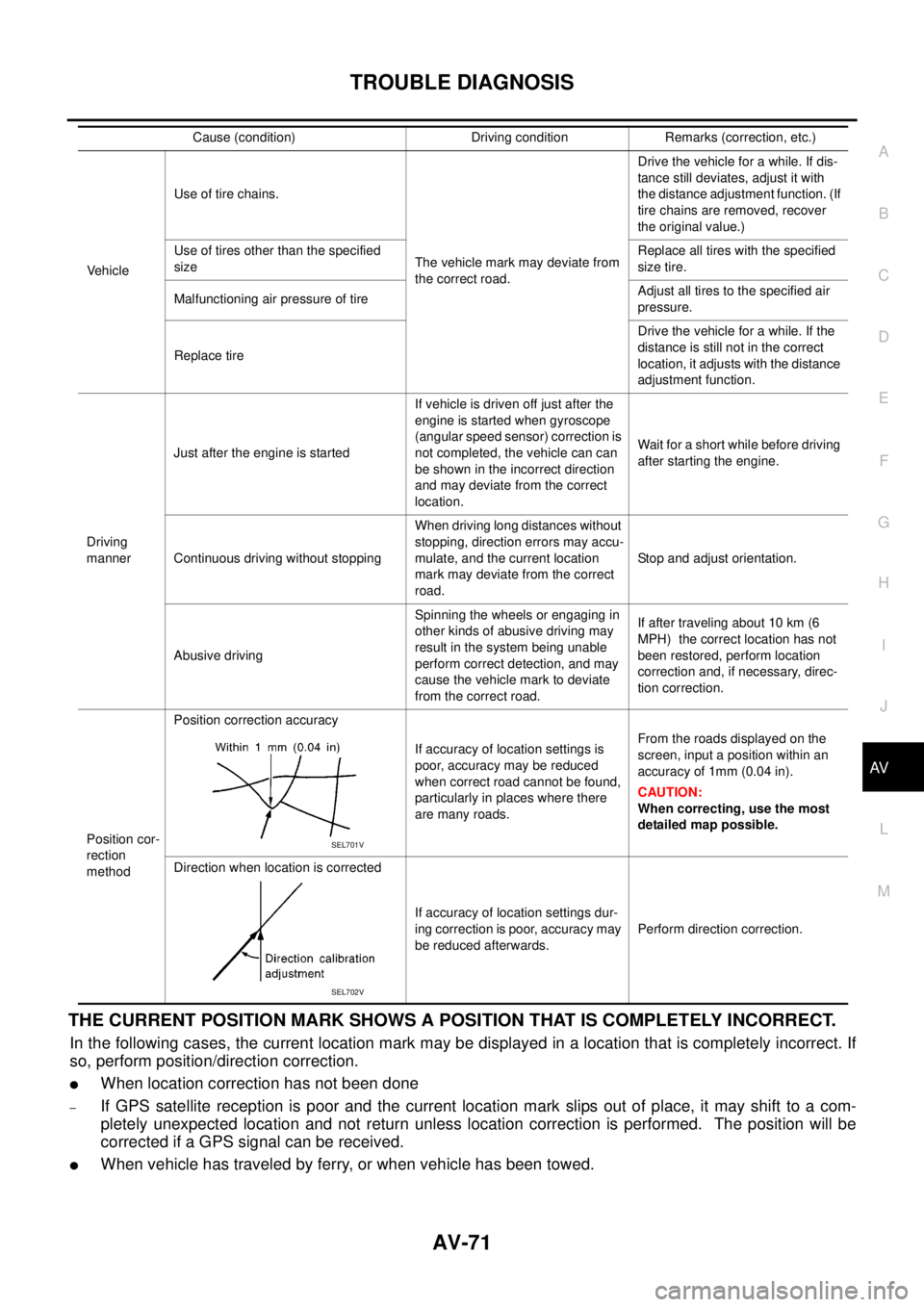
THE CURRENT POSITION MARK SHOWS A POSITION THAT IS COMPLETELY INCORRECT.
In the following cases, the current location mark may be displayed in a location that is completely incorrect. If
so, perform position/direction correction.
lWhen location correction has not been done
–If GPS satellite reception is poor and the current location mark slips out of place, it may shift to a com-
pletely unexpected location and not return unless location correction is performed. The position will be
corrected if a GPS signal can be received.
lWhen vehicle has traveled by ferry, or when vehicle has been towed.
VehicleUse of tire chains.
The vehicle mark may deviate from
the correct road.Drivethevehicleforawhile.Ifdis-
tance still deviates, adjust it with
the distance adjustment function. (If
tire chains are removed, recover
the original value.)
Use of tires other than the specified
sizeReplace all tires with the specified
size tire.
Malfunctioning air pressure of tireAdjust all tires to the specified air
pressure.
Replace tireDrive the vehicle for a while. If the
distance is still not in the correct
location, it adjusts with the distance
adjustment function.
Driving
mannerJust after the engine is startedIf vehicle is driven off just after the
engine is started when gyroscope
(angular speed sensor) correction is
not completed, the vehicle can can
be shown in the incorrect direction
and may deviate from the correct
location.Wait for a short while before driving
after starting the engine.
Continuous driving without stoppingWhen driving long distances without
stopping, direction errors may accu-
mulate, and the current location
mark may deviate from the correct
road.Stop and adjust orientation.
Abusive drivingSpinning the wheels or engaging in
other kinds of abusive driving may
result in the system being unable
perform correct detection, and may
cause the vehicle mark to deviate
from the correct road.If after traveling about 10 km (6
MPH) the correct location has not
been restored, perform location
correction and, if necessary, direc-
tion correction.
Position cor-
rection
methodPosition correction accuracy
If accuracy of location settings is
poor, accuracy may be reduced
when correct road cannot be found,
particularly in places where there
are many roads.From the roads displayed on the
screen, input a position within an
accuracy of 1mm (0.04 in).
CAUTION:
When correcting, use the most
detailed map possible.
Direction when location is corrected
If accuracy of location settings dur-
ing correction is poor, accuracy may
be reduced afterwards.Perform direction correction. Cause (condition) Driving condition Remarks (correction, etc.)
SEL701V
SEL702V
Page 889 of 3171

OVERHEATING CAUSE ANALYSIS
CO-5
C
D
E
F
G
H
I
J
K
L
MA
CO
Except cool-
ing system
parts mal-
function— Overload on engineAbusive drivingHigh engine rpm under no
load
Driving in low gear for
extended time
Driving at extremely high
speed
Powertrain system mal-
function
— Installed improper size
wheels and tires
Dragging brakes
Improper ignition timing
Blocked or restricted air
flowBlocked bumper —
— Blocked radiator grilleInstalled car brassiere
Mud contamination or
paper clogging
Blocked radiator —
Blocked condenser
Blocked air flow
Installed large fog lamp Symptom Check items
Page 1485 of 3171
CYLINDER HEAD
EM-103
C
D
E
F
G
H
I
J
K
L
MA
EM
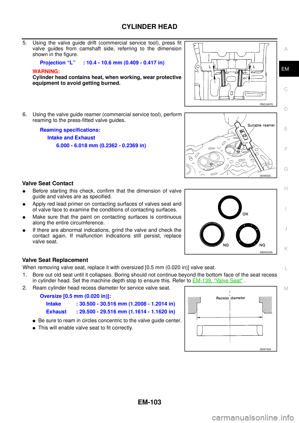
5. Using the valve guide drift (commercial service tool), press fit
valve guides from camshaft side, referring to the dimension
showninthefigure.
WARNING:
Cylinder head contains heat, when working, wear protective
equipment to avoid getting burned.
6. Using the valve guide reamer (commercial service tool), perform
reaming to the press-fitted valve guides.
Valve Seat Contact
lBefore starting this check, confirm that the dimension of valve
guide and valves are as specified.
lApply red lead primer on contacting surfaces of valves seat and
of valve face to examine the conditions of contacting surfaces.
lMake sure that the paint on contacting surfaces is continuous
along the entire circumference.
lIf there are abnormal indications, grind the valve and check the
contact again. If malfunction indications still persist, replace
valve seat.
Valve Seat Replacement
When removing valve seat, replace it with oversized [0.5 mm (0.020 in)] valve seat.
1. Bore out old seat until it collapses. Boring should not continue beyond the bottom face of the seat recess
in cylinder head. Set the machine depth stop to ensure this. Refer toEM-139, "
Valve Seat".
2. Ream cylinder head recess diameter for service valve seat.
lBe sure to ream in circles concentric to the valve guide center.
lThis will enable valve seat to fit correctly.Projection “L” : 10.4 - 10.6 mm (0.409 - 0.417 in)
PBIC2497E
Reaming specifications:
Intake and Exhaust
6.000 - 6.018 mm (0.2362 - 0.2369 in)
SEM932C
SBIA0322E
Oversize [0.5 mm (0.020 in)]:
Intake : 30.500 - 30.516 mm (1.2008 - 1.2014 in)
Exhaust : 29.500 - 29.516 mm (1.1614 - 1.1620 in)
SEM795A
Page 1621 of 3171
SERVICE DATA AND SPECIFICATIONS (SDS)
FSU-21
C
D
F
G
H
I
J
K
L
MA
B
FSU
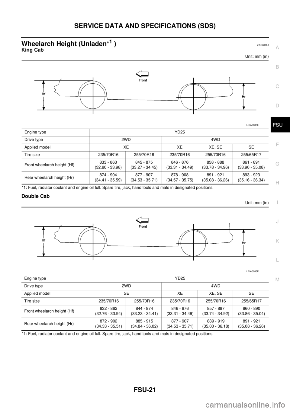
Wheelarch Height (Unladen*1)EES002L0
King Cab
Unit: mm (in)
*1: Fuel, radiator coolant and engine oil full. Spare tire, jack, hand tools and mats in designated positions.
Double Cab
Unit: mm (in)
*1: Fuel, radiator coolant and engine oil full. Spare tire, jack, hand tools and mats in designated positions.Engine type YD25
Drive type 2WD 4WD
Applied model XE XE XE, SE SE
Tire size 235/70R16 255/70R16 235/70R16 255/70R16 255/65R17
Front wheelarch height (Hf)833 - 863
(32.80 - 33.98)845 - 875
(33.27 - 34.45)846 - 876
(33.31 - 34.49)858 - 888
(33.78 - 34.96)861 - 891
(33.90 - 35.08)
Rear wheelarch height (Hr)874 - 904
(34.41 - 35.59)877 - 907
(34.53 - 35.71)878 - 908
(34.57 - 35.75)891 - 921
(35.08 - 36.26)893 - 923
(35.16 - 36.34)
LEIA0085E
Engine type YD25
Drive type 2WD 4WD
Applied model SE XE XE, SE SE
Tire size 235/70R16 255/70R16 235/70R16 255/70R16 255/65R17
Front wheelarch height (Hf)832 - 862
(32.76 - 33.94)844 - 874
(33.23 - 34.41)846 - 876
(33.31 - 34.49)857 - 887
(33.74 - 34.92)860 - 890
(33.86 - 35.04)
Rear wheelarch height (Hr)872 - 902
(34.33 - 35.51)885 - 915
(34.84 - 36.02)877 - 907
(34.53 - 35.71)889 - 919
(35.00 - 36.18)891 - 921
(35.08 - 36.26)
LEIA0085E
Page 1758 of 3171
IDX-6
ALPHABETICAL INDEX
P
P/SCKT - Wiring diagram ................................WW-57
Park/Neutral position switch ............................EC-342
Park/neutral position switch (A/T) ......................AT-99
Park/neutral position switch (M/T) ........MT-12,MT-19
Parking brake control ...........................................PB-2
Personal lamp ...................................................LT-145
Pilot bushing replacement ..............................EM-111
Piston pin inspection .......................................EM-125
Piston ring inspection ......................................EM-126
Piston to bore clearance .................................EM-129
Planetary carrier (Transfer) ..............................TF-129
PNP/SW - Wiring diagram ...............................EC-343
POWER - Wiring diagram ....................................PG-5
Power seat .........................................................SE-10
Power steering fluid level ..................................MA-37
Power steering gear ...........................................PS-14
Power steering oil pump ....................................PS-25
Power steering system bleeding ..........................PS-6
Power supply routing ...........................................PG-4
Power window ...................................................GW-15
Precations for Leak detection dye ....ATC-14,MTC-14
Precautions (General) ...........................................GI-4
Pre-delivery inspection .......................................MA-5
Pressure plate - See Clutch cover .....................CL-17
Pressure switch 1 ..............................AT-139,AT-156
Pressure switch 2 ............................................AT-154
Pressure switch 3 ..............................AT-134,AT-158
Pressure switch 5 ..............................AT-144,AT-160
Pressure switch 6 ..............................AT-149,AT-162
Pressure test (A/T) .............................................AT-44
Priming pump .....................................................EC-23
Propeller shaft ............................................PR-3,PR-7
Propeller shaft inspection .................................MA-32
Propeller shaft on vehicle service ........................PR-7
Propeller shaft vibration .............................PR-3,PR-7
Q
Quick-glow system ...........................................EC-295
R
R/FOG - Wiring diagram .....................................LT-89
Radiator ................................................CO-11,CO-15
Rear bumper .......................................................EI-17
Rear case (Transfer) ...........................TF-114,TF-120
Rear combination lamp removal and installation ..........
LT-144
Rear cover packing replacement diff. ..............FFD-14
Rear door ..........................................................GW-38
Rear seat ...........................................................SE-29
Rear seat belt ............................................SB-7,SB-9
Rear window .....................................................GW-43
Rear window defogger ......................................GW-47
Refrigerant connection precaution ........ATC-5,MTC-5
Refrigerant discharging evacuating chargingATC-138,
MTC-118
Refrigerant general precaution ............ATC-5,MTC-5
Refrigerant lines ...........ATC-138,ATC-146,ATC-147,
MTC-118
,MTC-126,MTC-127
Refrigerant pressure sensor ............EC-325,ATC-92,
ATC-147
,MTC-85,MTC-127
Refrigeration cycle ...........................ATC-20,MTC-20
Relay box ..........................................................PG-85
Removal and installation (A/T) .........................AT-247
Removal and installation (Transfer) .................TF-111
Reverse idler shaft (M/T) ..................................MT-21
Reverse lamp switch (M/T) - See Back-up lamp switch
(M/T) .....................................................MT-12
,MT-19
Reverse main gear (M/T) ..................................MT-21
Revolution sensor (A/T) .....................AT-103,AT-238
Road wheel size .................................................GI-60
Rocker cover .....................................................EM-56
Room lamp ......................................................LT-145
Room lamp - See Interior lamp ........................LT-145
ROOM/L - Wiring diagram ...............................LT-149
RP/SEN - Wiring diagram ................................EC-326
S
S/SIG - Wiring diagram ....................................EC-348
SCTC/V - Wiring diagram ................................EC-219
SEAT - Wiring diagram ..........................SE-10,SE-11
Seat belt inspection ..............................SB-11,MA-40
Seat belt pre-tensioner ...................................SRS-47
Seat belt pre-tensioner disposal .....................SRS-49
Seat belt, front ...........................................SB-3,SB-5
Seat belt, rear ............................................SB-7,SB-9
Seat, front ..........................................................SE-20
Seat, rear ...........................................................SE-29
Self-diagnosis (Transfer) ...................................TF-49
SHIFT - Wiring diagram ...................................AT-213
Shift control (Transfer) .....................................TF-135
Shift control components (M/T) .........................MT-23
Shift fork (M/T) ..................................................MT-23
Shift lever ..........................................................MT-13
Shift lock system ..............................................AT-212
Shock absorber (front) ....................................FSU-11
Shock absorber (rear) .......................................RSU-6
Side air bag .....................................................SRS-43
Side air bag (satellite) sensor .........................SRS-46
Side curtain air bag .........................................SRS-44
Side trim ..............................................................EI-33
SMJ (super multiple junction) ...........................PG-81
Spare tire size .....................................................GI-60
Speedometer ........................................................DI-4
Spiral cable .....................................................SRS-38
SROOF - Wiring diagram ...................................RF-14
SRS - See Supplemental Restraint System .....SRS-6
SRS - Wiring diagram .....................................SRS-13
SRS Trouble diagnoses ....................................SRS-9
Stabilizer bar (front) ........................................FSU-12
Stall test (A/T) ....................................................AT-43
Standardized relay ............................................PG-79
START - Wiring diagram ....................................SC-28
Start signal .......................................................EC-348
Page 1759 of 3171
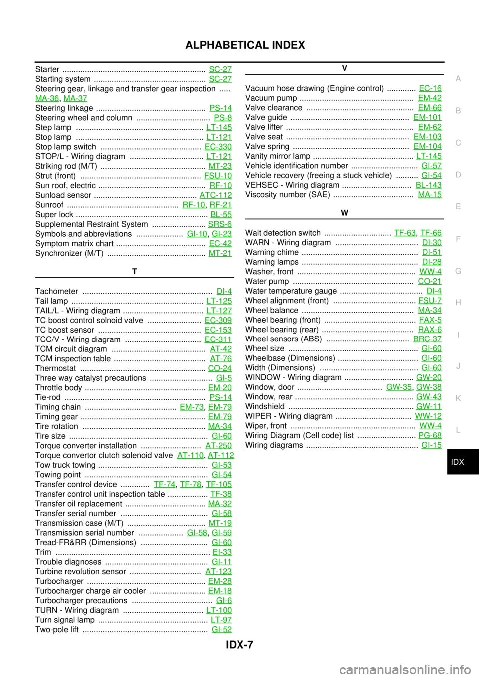
IDX-7
A
C
D
E
F
G
H
I
J
K
L B
IDX
ALPHABETICAL INDEX
Starter ................................................................SC-27
Starting system ..................................................SC-27
Steering gear, linkage and transfer gear inspection .....
MA-36
,MA-37
Steering linkage .................................................PS-14
Steering wheel and column .................................PS-8
Step lamp .........................................................LT-145
Stop lamp .........................................................LT-121
Stop lamp switch .............................................EC-330
STOP/L - Wiring diagram .................................LT-121
Striking rod (M/T) ...............................................MT-23
Strut (front) ......................................................FSU-10
Sun roof, electric ................................................RF-10
Sunload sensor ..............................................ATC-112
Sunroof ..................................................RF-10,RF-21
Super lock ...........................................................BL-55
Supplemental Restraint System ........................SRS-6
Symbols and abbreviations .....................GI-10,GI-23
Symptom matrix chart ........................................EC-42
Synchronizer (M/T) ............................................MT-21
T
Tachometer ..........................................................DI-4
Tail lamp ...........................................................LT-125
TAIL/L - Wiring diagram ....................................LT-127
TC boost control solnoid valve ........................EC-309
TC boost sensor ..............................................EC-153
TCC/V - Wiring diagram ..................................EC-311
TCM circuit diagram ..........................................AT-42
TCM inspection table .........................................AT-76
Thermostat ........................................................CO-24
Three way catalyst precautions ............................GI-5
Throttle body ......................................................EM-20
Tie-rod ...............................................................PS-14
Timing chain .........................................EM-73,EM-79
Timing gear ........................................................EM-79
Tire rotation .......................................................MA-34
Tire size ..............................................................GI-60
Torque converter installation ...........................AT-250
Torque convertor clutch solenoid valveAT-110,AT-112
Tow truck towing .................................................GI-53
Towing point .......................................................GI-54
Transfer control device .............TF-74,TF-78,TF-105
Transfer control unit inspection table ..................TF-38
Transfer oil replacement ....................................MA-32
Transfer serial number .......................................GI-58
Transmission case (M/T) ...................................MT-19
Transmission serial number ....................GI-58,GI-59
Tread-FR&RR (Dimensions) ..............................GI-60
Trim .....................................................................EI-33
Trouble diagnoses ..............................................GI-11
Turbine revolution sensor ................................AT-123
Turbocharger .....................................................EM-28
Turbocharger charge air cooler .........................EM-18
Turbocharger precautions ....................................GI-6
TURN - Wiring diagram ....................................LT-100
Turn signal lamp .................................................LT-97
Two-pole lift ........................................................GI-52
V
Vacuum hose drawing (Engine control) .............EC-16
Vacuum pump ...................................................EM-42
Valve clearance ................................................EM-66
Valve guide .....................................................EM-101
Valve lifter .........................................................EM-62
Valve seat .......................................................EM-103
Valve spring ....................................................EM-104
Vanity mirror lamp .............................................LT-145
Vehicle identification number ..............................GI-57
Vehicle recovery (freeing a stuck vehicle) ..........GI-54
VEHSEC - Wiring diagram ...............................BL-143
Viscosity number (SAE) ....................................MA-15
W
Wait detection switch ..............................TF-63
,TF-66
WARN - Wiring diagram .....................................DI-30
Warning chime ....................................................DI-51
Warning lamps ....................................................DI-28
Washer, front .....................................................WW-4
Water pump ......................................................CO-21
Water temperature gauge .....................................DI-4
Wheel alignment (front) .....................................FSU-7
Wheel balance ..................................................MA-34
Wheel bearing (front) .........................................FAX-5
Wheel bearing (rear) .........................................RAX-6
Wheel sensors (ABS) .....................................BRC-37
Wheel size ..........................................................GI-60
Wheelbase (Dimensions) ....................................GI-60
Width (Dimensions) ............................................GI-60
WINDOW - Wiring diagram ...............................GW-20
Window, door ......................................GW-35,GW-38
Window, rear .....................................................GW-43
Windshield ........................................................GW-11
WIPER - Wiring diagram ..................................WW-12
Wiper, front ........................................................WW-4
Wiring Diagram (Cell code) list ..........................PG-68
Wiring diagrams ..................................................GI-15