2005 NISSAN NAVARA washer fluid
[x] Cancel search: washer fluidPage 12 of 3171

AT-4
Sensor 2 ...............................................................218
Parking Components (2WD Models Only) ............230
Rear Oil Seal ........................................................237
Revolution Sensor Components (2WD Models
Only) .....................................................................238
AIR BREATHER HOSE ...........................................243
Removal and Installation ......................................243
A/T FLUID COOLER ...............................................244
Removal and Installation ......................................244
TRANSMISSION ASSEMBLY ................................247
Removal and Installation ......................................247
OVERHAUL .............................................................251
Components .........................................................251
Oil Channel ...........................................................259
Locations of Adjusting Shims, Needle Bearings,
Thrust Washers and Snap Rings ..........................261
DISASSEMBLY .......................................................263
Disassembly .........................................................263
REPAIR FOR COMPONENT PARTS ......................281
Oil Pump ...............................................................281
Front Sun Gear, 3rd One-way Clutch ...................284Front Carrier, Input Clutch, Rear Internal Gear .....286
Mid Sun Gear, Rear Sun Gear, High and Low
Reverse Clutch Hub ..............................................291
High and Low Reverse Clutch ..............................296
Direct Clutch .........................................................298
ASSEMBLY .............................................................300
Assembly (1) .........................................................300
Adjustment ............................................................313
Assembly (2) .........................................................316
SERVICE DATA AND SPECIFICATIONS (SDS) ....323
General Specifications ..........................................323
Stall Speed ............................................................323
Line Pressure ........................................................323
Vehicle Speed at Which Gear Shifting Occurs ......324
Vehicle Speed at Which Lock-Up Occurs/Releases.324
A/T Fluid Temperature Sensor ..............................324
Vehicle Speed Sensor A/T (Revolution Sensor) ...325
Turbine Revolution Sensor ....................................325
Reverse Brake ......................................................325
Total End Play .......................................................325
Page 15 of 3171
PRECAUTIONS
AT-7
D
E
F
G
H
I
J
K
L
MA
B
AT
PRECAUTIONSPFP:00001
Precautions for Supplemental Restraint System (SRS) “AIR BAG” and “SEAT
BELT PRE-TENSIONER”
ECS00IPT
The Supplemental Restraint System such as “AIR BAG” and “SEAT BELT PRE-TENSIONER”, used along
with a front seat belt, helps to reduce the risk or severity of injury to the driver and front passenger for certain
types of collision. Information necessary to service the system safely is included in the SRS and SB section of
this Service Manual.
WARNING:
lTo avoid rendering the SRS inoperative, which could increase the risk of personal injury or death
in the event of a collision which would result in air bag inflation, all maintenance must be per-
formed by an authorized NISSAN/INFINITI dealer.
lImproper maintenance, including incorrect removal and installation of the SRS, can lead to per-
sonal injury caused by unintentional activation of the system. For removal of Spiral Cable and Air
Bag Module, see the SRS section.
lDo not use electrical test equipment on any circuit related to the SRS unless instructed to in this
Service Manual. SRS wiring harnesses can be identified by yellow and/or orange harnesses or
harness connectors.
PrecautionsECS00IPR
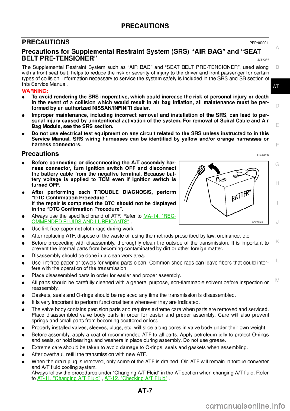
lBefore connecting or disconnecting the A/T assembly har-
ness connector, turn ignition switch OFF and disconnect
the battery cable from the negative terminal. Because bat-
tery voltage is applied to TCM even if ignition switch is
turned OFF.
lAfter performing each TROUBLE DIAGNOSIS, perform
“DTC Confirmation Procedure”.
If the repair is completed the DTC should not be displayed
in the “DTC Confirmation Procedure”.
lAlways use the specified brand of ATF. Refer toMA-14, "REC-
OMMENDED FLUIDS AND LUBRICANTS".
lUse lint-free paper not cloth rags during work.
lAfter replacing ATF, dispose of the waste oil using the methods prescribed by law, ordinance, etc.
lBefore proceeding with disassembly, thoroughly clean the outside of the transmission. It is important to
prevent the internal parts from becoming contaminated by dirt or other foreign matter.
lDisassembly should be done in a clean work area.
lUse lint-free paper or towels for wiping parts clean. Common shop rags can leave fibers that could inter-
fere with the operation of the transmission.
lPlace disassembled parts in order for easier and proper assembly.
lAll parts should be carefully cleaned with a general purpose, non-flammable solvent before inspection or
reassembly.
lGaskets, seals and O-rings should be replaced any time the transmission is disassembled.
lIt is very important to perform functional tests whenever they are indicated.
lThe valve body contains precision parts and requires extreme care when parts are removed and serviced.
Place disassembled valve body parts in order for easier and proper assembly. Care will also prevent
springs and small parts from becoming scattered or lost.
lProperly installed valves, sleeves, plugs, etc. will slide along bores in valve body under their own weight.
lBefore assembly, apply a coat of recommended ATF to all parts. Apply petroleum jelly to protect O-rings
and seals, or hold bearings and washers in place during assembly. Do not use grease.
lExtreme care should be taken to avoid damage to O-rings, seals and gaskets when assembling.
lAfter overhaul, refill the transmission with new ATF.
lWhen the drain plug is removed, only some of the ATF is drained. Old ATF will remain in torque converter
and A/T fluid cooling system.
Always follow the procedures under “Changing A/T Fluid” in the AT section when changing A/T fluid. Refer
toAT-11, "
Changing A/T Fluid",AT-12, "Checking A/T Fluid".
SEF289H
Page 255 of 3171
TRANSMISSION ASSEMBLY
AT-247
D
E
F
G
H
I
J
K
L
MA
B
AT
TRANSMISSION ASSEMBLYPFP:31020
Removal and InstallationECS00HR4
COMPONENTS
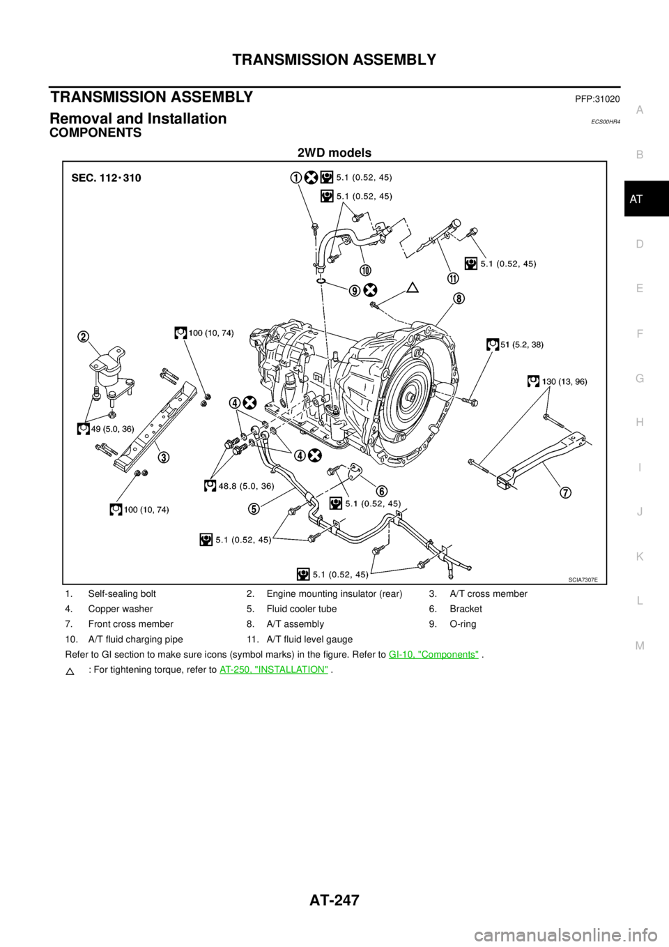
2WD models
SCIA7307E
1. Self-sealing bolt 2. Engine mounting insulator (rear) 3. A/T cross member
4. Copper washer 5. Fluid cooler tube 6. Bracket
7. Front cross member 8. A/T assembly 9. O-ring
10. A/T fluid charging pipe 11. A/T fluid level gauge
Refer to GI section to make sure icons (symbol marks) in the figure. Refer toGI-10, "
Components".
: For tightening torque, refer toAT- 2 5 0 , "
INSTALLATION".
Page 256 of 3171
AT-248
TRANSMISSION ASSEMBLY
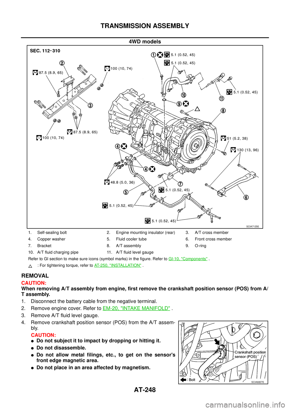
4WD models
REMOVAL
CAUTION:
When removing A/T assembly from engine, first remove the crankshaft position sensor (POS) from A/
T assembly.
1. Disconnect the battery cable from the negative terminal.
2. Remove engine cover. Refer toEM-20, "
INTAKE MANIFOLD".
3. Remove A/T fluid level gauge.
4. Remove crankshaft position sensor (POS) from the A/T assem-
bly.
CAUTION:
lDo not subject it to impact by dropping or hitting it.
lDo not disassemble.
lDo not allow metal filings, etc., to get on the sensor's
front edge magnetic area.
lDo not place in an area affected by magnetism.
SCIA7125E
1. Self-sealing bolt 2. Engine mounting insulator (rear) 3. A/T cross member
4. Copper washer 5. Fluid cooler tube 6. Front cross member
7. Bracket 8. A/T assembly 9. O-ring
10. A/T fluid charging pipe 11. A/T fluid level gauge
Refer to GI section to make sure icons (symbol marks) in the figure. Refer toGI-10, "
Components".
: For tightening torque, refer toAT-250, "
INSTALLATION".
SCIA6827E
Page 484 of 3171
ATC-150
REFRIGERANT LINES
CAUTION:
Replace the O-rings on the A/C low-pressure flexible A/C hose and the high-pressure A/C pipe with
new ones. Apply compressor oil to the O-rings for installation.
Removal and Installation for Expansion ValveEJS006CZ
REMOVAL
1. Discharge the refrigerant. Refer toATC-138, "HFC-134a (R-134a) Service Procedure".
2. Remove the heater and cooling unit assembly. Refer toATC-126, "
REMOVAL".
3. Remove the heater core and evaporator pipes grommet.
4. Remove the expansion valve.
INSTALLATION
Installation is in the reverse order of removal.
CAUTION:
lReplace the O-rings on then expansion valve and the A/C refrigerant pipes with new ones, then
apply compressor oil to them for installation.
lAfter charging refrigerant, check for leaks.
Checking for Refrigerant LeaksEJS006D1
Perform a visual inspection of all refrigeration parts, fittings, hoses and components for signs of A/C lubricant
leakage, damage and corrosion. A/C lubricant leakage may indicate an area of refrigerant leakage. Allow
extra inspection time in these areas when using either an electronic refrigerant leak detector or fluorescent
dye leak detector.
If dye is observed, confirm the leak with an electronic refrigerant leak detector. It is possible a prior leak was
repaired and not properly cleaned.
When searching for leaks, do not stop when one leak is found but continue to check for additional leaks at all
system components and connections.
When searching for refrigerant leaks using an electronic leak detector, move the probe along the suspected
leak area at 1 to 2 inches per second and no further than 1/4 inch from the component.
CAUTION:
Moving the electronic leak detector probe slower and closer to the suspected leak area will improve
the chances of finding a leak.
Checking System for Leaks Using the Fluorescent Leak DetectorEJS006D2
1. Check A/C system for leaks using the UV lamp and safety goggles [SST: J-42220] in a low sunlight area
(area without windows preferable). Illuminate all components, fittings and lines. The dye will appear as a
bright green/yellow area at the point of leakage. Fluorescent dye observed at the evaporator drain open-
ing indicates an evaporator core assembly (tubes, core or expansion valve) leak.
2. If the suspected area is difficult to see, use an adjustable mirror or wipe the area with a clean shop rag or
cloth, with the UV lamp for dye residue.
3. After the leak is repaired, remove any residual dye using dye cleaner [SST: J-43872] to prevent future mis-
diagnosis.
4. Perform a system performance check and verify the leak repair with an approved electronic refrigerant
leak detector.
NOTE:
Other gases in the work area or substances on the A/C components, for example, anti-freeze, windshield
washer fluid, solvents and lubricants, may falsely trigger the leak detector. Make sure the surfaces to be
checked are clean.
Cleanwithadryclothorblowoffwithshopair.
Do not allow the sensor tip of the detector to contact with any substance. This can also cause false readings
and may damage the detector.Expansion valve bolts : 4 N·m (0.41 kg-m, 35 in-lb)
A/C refrigerant pipe to expansion valve bolt : Refer toATC-140, "
Components"
.
Page 799 of 3171
BRAKE TUBE AND HOSE
BR-13
C
D
E
G
H
I
J
K
L
MA
B
BR
CAUTION:
lAll brake tubes and hoses must be free from excessive bending, twisting and pulling.
lMake sure that there is no interference with other parts when turning steering both clockwise and
counterclockwise.
lBrake tube and hose is an important safety part. Always disassemble the parts and retighten their
fittings, if a brake fluid leak is detected. Replace applicable part with a new one, if damaged part is
detected.
lBe careful not to splash brake fluid on painted areas; it may cause paint damage. If brake fluid is
splashed on painted surfaces of body, immediately wipe off them and wash it away with water.
lDo not bend or twist brake hose sharply, or strongly pull it.
lCover the open end of brake tube and hoses when disconnecting to prevent entrance of dirt.
lRefill with new brake fluid “DOT 3” or “DOT 4”.
lNever reuse drained brake fluid.
Removal and Installation of Front Brake Tube and Brake HoseEFS005SM
REMOVAL
1. Drain brake fluid. Refer toBR-10, "Drain and Refill".
2. Using a flare nut wrench, disconnect brake tube from brake hose.
3. Remove union bolt and remove brake hose from caliper assembly.
4. Remove lock plate and remove brake hose from vehicle.
INSTALLATION
1. Assemble the union bolt and copper washers to the brake hose.
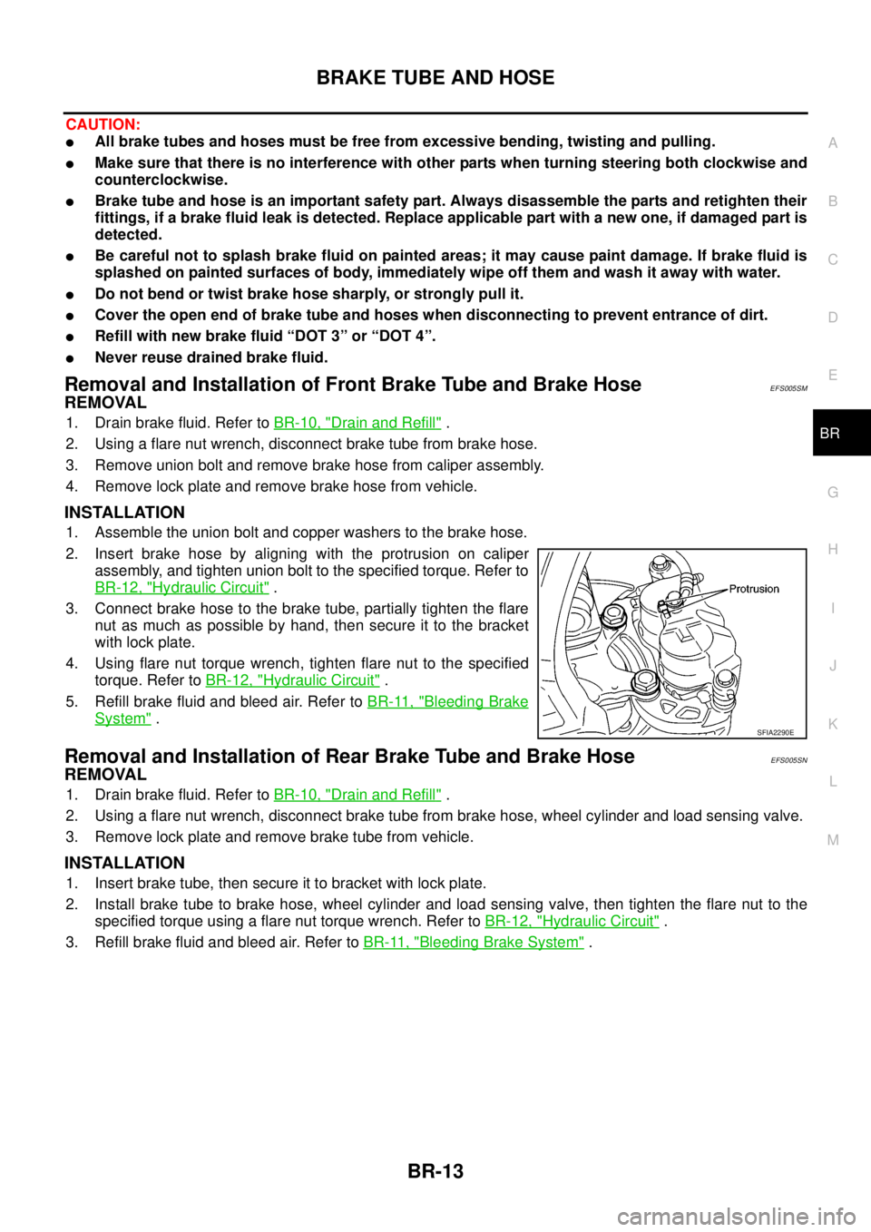
2. Insert brake hose by aligning with the protrusion on caliper
assembly, and tighten union bolt to the specified torque. Refer to
BR-12, "
Hydraulic Circuit".
3. Connect brake hose to the brake tube, partially tighten the flare
nut as much as possible by hand, then secure it to the bracket
with lock plate.
4. Using flare nut torque wrench, tighten flare nut to the specified
torque. Refer toBR-12, "
Hydraulic Circuit".
5. Refill brake fluid and bleed air. Refer toBR-11, "
Bleeding Brake
System".
Removal and Installation of Rear Brake Tube and Brake HoseEFS005SN
REMOVAL
1. Drain brake fluid. Refer toBR-10, "Drain and Refill".
2. Using a flare nut wrench, disconnect brake tube from brake hose, wheel cylinder and load sensing valve.
3. Remove lock plate and remove brake tube from vehicle.
INSTALLATION
1. Insert brake tube, then secure it to bracket with lock plate.
2. Install brake tube to brake hose, wheel cylinder and load sensing valve, then tighten the flare nut to the
specified torque using a flare nut torque wrench. Refer toBR-12, "
Hydraulic Circuit".
3. Refill brake fluid and bleed air. Refer toBR-11, "
Bleeding Brake System".
SFIA2290E
Page 816 of 3171
BR-30
REAR DRUM BRAKE
REAR DRUM BRAKE
PFP:43206
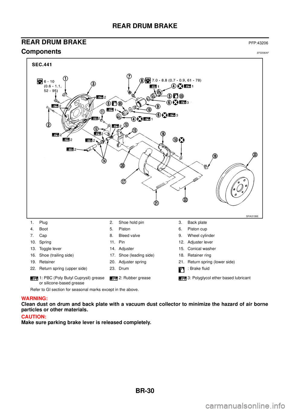
ComponentsEFS006AF
WARNING:
Clean dust on drum and back plate with a vacuum dust collector to minimize the hazard of air borne
particles or other materials.
CAUTION:
Make sure parking brake lever is released completely.
1. Plug 2. Shoe hold pin 3. Back plate
4. Boot 5. Piston 6. Piston cup
7. Cap 8. Bleed valve 9. Wheel cylinder
10. Spring 11. Pin 12. Adjuster lever
13. Toggle lever 14. Adjuster 15. Conical washer
16. Shoe (trailing side) 17. Shoe (leading side) 18. Retainer ring
19. Retainer 20. Adjuster spring 21. Return spring (lower side)
22. Return spring (upper side) 23. Drum : Brake fluid
1: PBC (Poly Butyl Cuprysil) grease
or silicone-based grease2: Rubber grease 3: Polyglycol ether based lubricant
Refer to GI section for seasonal marks except in the above.
SFIA3199E
Page 875 of 3171
OPERATING CYLINDER
CL-11
D
E
F
G
H
I
J
K
L
MA
B
CL
OPERATING CYLINDERPFP:30620
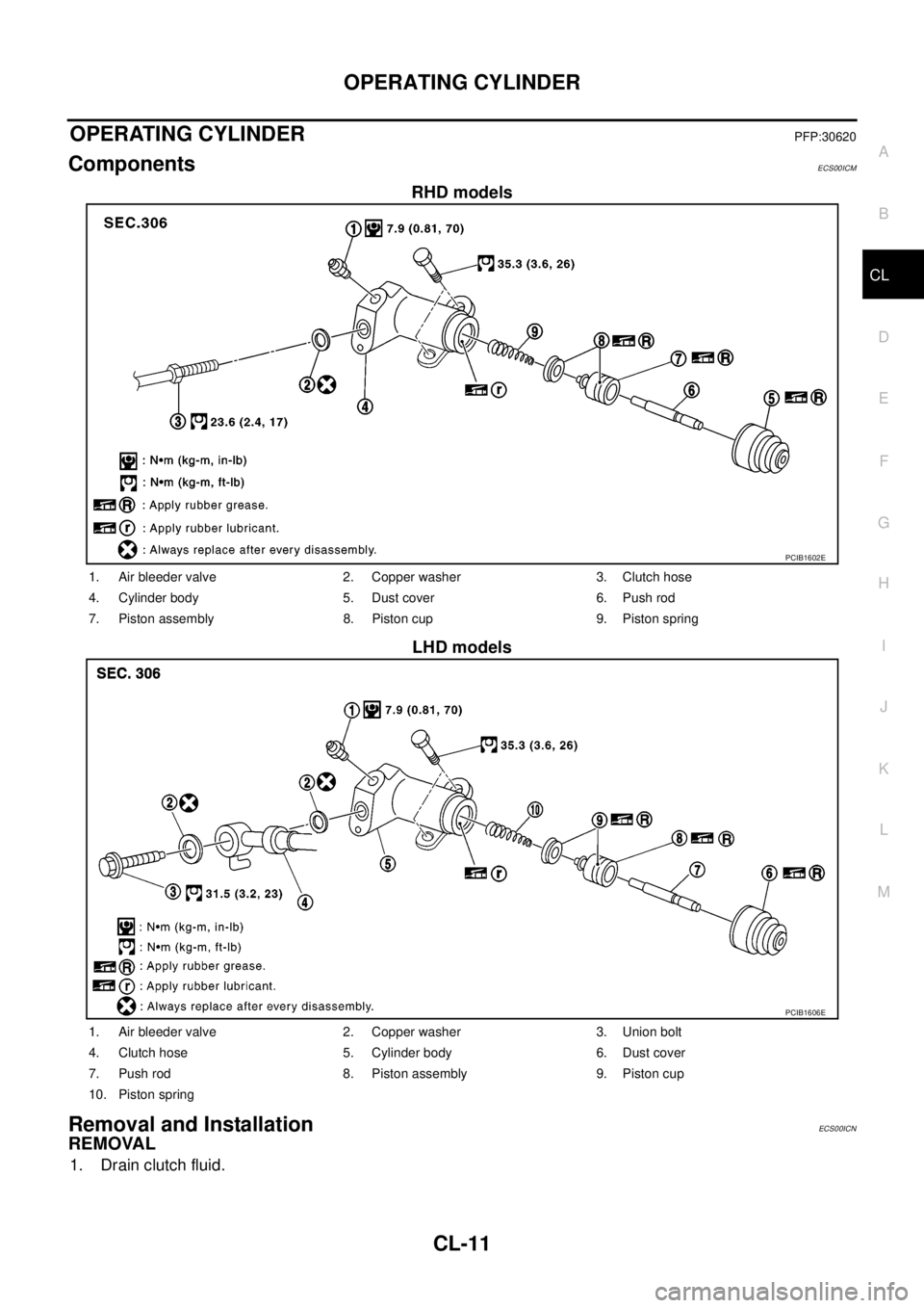
ComponentsECS00ICM
RHD models
LHD models
Removal and InstallationECS00ICN
REMOVAL
1. Drain clutch fluid.
PCIB1602E
1. Air bleeder valve 2. Copper washer 3. Clutch hose
4. Cylinder body 5. Dust cover 6. Push rod
7. Piston assembly 8. Piston cup 9. Piston spring
PCIB1606E
1. Air bleeder valve 2. Copper washer 3. Union bolt
4. Clutch hose 5. Cylinder body 6. Dust cover
7. Push rod 8. Piston assembly 9. Piston cup
10. Piston spring