2005 NISSAN NAVARA CD player
[x] Cancel search: CD playerPage 489 of 3171

AV-1
AUDIO-VISUAL SYSTEM
K ELECTRICAL
CONTENTS
C
D
E
F
G
H
I
J
L
M
SECTIONAV
A
B
AV
AUDIO-VISUAL SYSTEM
PRECAUTIONS .......................................................... 3
Precautions for Supplemental Restraint System
(SRS)“AIRBAG”and“SEATBELTPRE-TEN-
SIONER” .................................................................. 3
Wiring Diagrams and Trouble Diagnosis .................. 3
SYSTEM DESCRIPTION ............................................ 4
System Functions ..................................................... 4
AUDIO ................................................................... 4
NATS AUDIO LINK (WITHOUT NAVIGATION
SYSTEM) .............................................................. 4
VEHICLE INFORMATION SYSTEM ..................... 5
NAVIGATION SYSTEM ......................................... 5
HANDS-FREE PHONE ......................................... 7
Component Description ............................................ 8
AUDIO UNIT ......................................................... 8
NAVI CONTROL UNIT .......................................... 8
GPS ANTENNA .................................................... 9
DISPLAY UNIT ...................................................... 9
AV SWITCH .......................................................... 9
Component Parts Location ..................................... 10
Location Of Antenna .............................................. 10
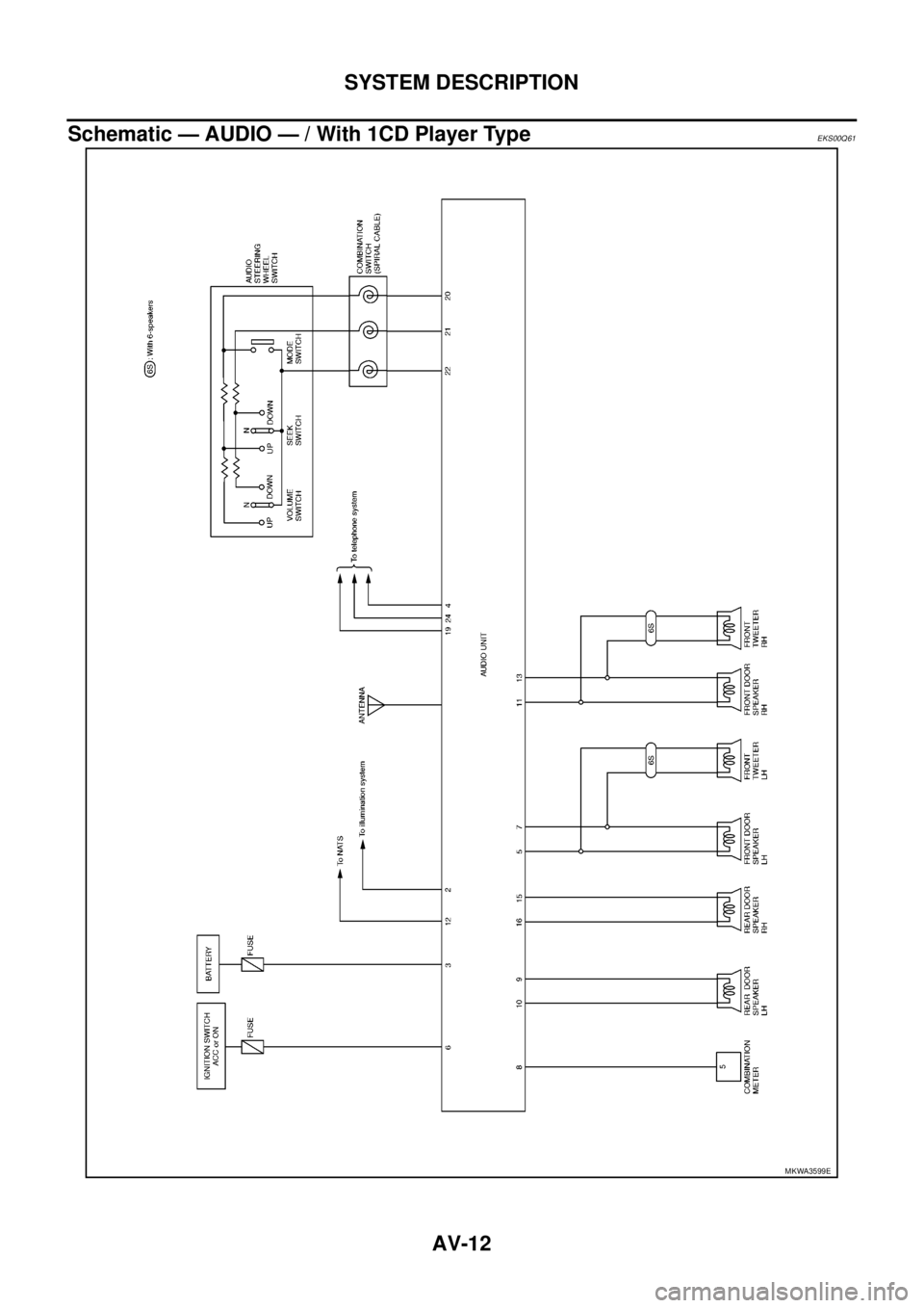
Schematic — AUDIO — / With 1CD Player Type... 12
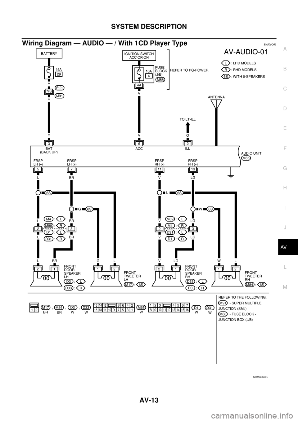
Wiring Diagram — AUDIO — / With 1CD Player Type
... 13
Schematic — AUDIO — / With 6CD Player Type... 16
Wiring Diagram — AUDIO — / With 6CD Player Type
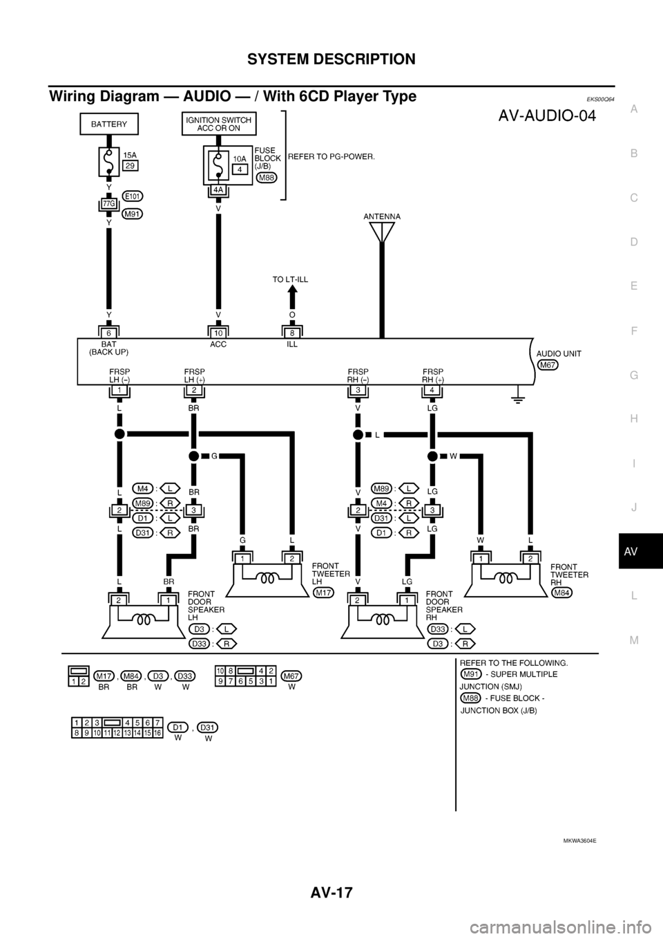
... 17
Schematic — NAVI — ............................................ 20
Wiring Diagram — NAVI — .................................... 21
Schematic — NAVI — / COMM .............................. 28
Wiring Diagram — NAVI — / COMM ...................... 29
Wiring Diagram — TELEPHONE (PRE WIRE) —
/ Without NAVI ........................................................ 32
CAN Communication .............................................. 33
SYSTEM DESCRIPTION .................................... 33
TERMINALS AND REFERENCE VALUE FOR CON-
TROL UNIT ............................................................... 34
Audio Unit (1CD Player Type) ................................ 34
Audio Unit (6CD Player Type) Without NAVI .......... 35Audio Unit (With NAVI) ........................................... 37
NAVI Control Unit ................................................... 38
Display Unit ............................................................ 41
DIAGNOSIS SYSTEM ............................................... 44
Navigation System Diagnosis Function .................. 44
On Bord Self-Diagnosis Function ........................... 44
DESCRIPTION .................................................... 44
DIAGNOSIS ITEM ............................................... 44
OPERATION PROCEDURE ................................ 45
Self Diagnosis Mode ............................................... 46
ERROR DETECTION RANGE OF SELF-DIAG-
NOSIS MODE ..................................................... 47
DIAGNOSIS RESULTS ....................................... 47
Confirmation/Adjustment Mode .............................. 48
SCREEN TROUBLE DIAGNOSIS ...................... 49
VEHICLE SIGNALS ............................................ 49
SPEAKER TEST ................................................. 50
NAVIGATION ....................................................... 50
ERROR HISTORY ............................................... 51
VEHICLE CAN DIAGNOSIS ............................... 53
AV COMM DIAGNOSIS ....................................... 54
HANDSFREE PHONE ........................................ 54
BLUETOOTH ....................................................... 54
DELETE UNIT CONNECTION LOG ................... 55
CONSULT-II Functions ........................................... 56
CONSULT-II FUNCTIONS ................................... 56
CONSULT-II BASIC OPERATION PROCEDURE
... 56
SELF-DIAG RESULTS ........................................ 56
DATA MONITOR ................................................. 58
AV COMM MONITOR .......................................... 59
ECU PART NUMBER .......................................... 60
TROUBLE DIAGNOSIS ............................................ 61
Navigation System .................................................. 61
RGB Image ............................................................. 61
Voice Activated Control System ............................. 62
Steering Wheel Switch ............................................ 63
Component Parts Inspection .................................. 63
STEERING WHEEL SWITCH UNIT INSPEC-
Page 490 of 3171

AV-2
TION .................................................................... 63
Example of Symptoms Not Malfunction .................. 65
BASIC OPERATION ............................................ 65
VEHICLE ICON ................................................... 65
MAP DVD-ROM ................................................... 66
ROUTE CALCULATION AND VISUAL GUID-
ANCE ................................................................... 66
VOICE GUIDANCE ............................................. 67
VOICE RECOGNITION ....................................... 67
EXAMPLES OF CURRENT LOCATION MARK
DISPLACEMENT ................................................. 68
THE CURRENT POSITION MARK SHOWS A
POSITION THAT IS COMPLETELY INCOR-
RECT. .................................................................. 71
THE CURRENT POSITION MARK JUMPS. ....... 72
THE CURRENT LOCATION MARK IS IN A
RIVER OR THE SEA. .......................................... 72
CURRENT LOCATION MARK ROTATES WITH-
OUT OPERATION ............................................... 72
WHEN DRIVING ON THE SAME ROAD, SOME-
TIMES THE CURRENT LOCATION MARK IS IN
THE CORRECT PLACE AND SOMETIMES IT IS
IN THE INCORRECT PLACE. ............................. 72
LOCATION CORRECTION BY MAP MATCHING
IS SLOW. ............................................................. 72
ALTHOUGH THE GPS RECEIVING DISPLAY IS
GREEN, THE VEHICLE MARK DOES NOT
RETURN TO THE CORRECT LOCATION. ......... 72
THE NAME OF THE CURRENT PLACE IS NOT
DISPLAYED. ........................................................ 72
THE DISPLAY IS DIFFERENT BETWEEN BIRD-
VIEW® AND (FLAT) MAP DISPLAY. ................... 72
REMOVAL AND INSTALLATION ............................. 73
Auido Unit (1CD Player Type) ................................ 73
REMOVAL ........................................................... 73INSTALLATION .................................................... 73
Audio Unit ( 6CD Player Type ) Without NAVI ........ 73
REMOVAL ............................................................ 73
INSTALLATION .................................................... 73
Audio Unit (6CD Player Type) With NAVI ............... 74
REMOVAL ............................................................ 74
INSTALLATION .................................................... 74
Front Door Speaker ................................................ 74
REMOVAL ............................................................ 74
INSTALLATION .................................................... 74
Rear Door Speaker ................................................. 74
REMOVAL ............................................................ 74
INSTALLATION .................................................... 74
Tweeter ................................................................... 75
REMOVAL ............................................................ 75
INSTALLATION .................................................... 75
Roof Antenna .......................................................... 75
REMOVAL ............................................................ 75
INSTALLATION .................................................... 75
NAVI Control Unit .................................................... 75
REMOVAL ............................................................ 75
INSTALLATION .................................................... 75
GPS Antenna .......................................................... 76
REMOVAL ............................................................ 76
INSTALLATION .................................................... 76
Display Unit ............................................................. 77
REMOVAL ............................................................ 77
INSTALLATION .................................................... 77
AV Switch ................................................................ 77
REMOVAL ............................................................ 77
INSTALLATION .................................................... 77
Microphone ............................................................. 77
REMOVAL ............................................................ 77
INSTALLATION .................................................... 77
Page 492 of 3171

AV-4
SYSTEM DESCRIPTION
SYSTEM DESCRIPTION
PFP:00000
System FunctionsEKS00Q5X
Refer to Owner's Manual for audio system operating instructions.
AUDIO
Speed Sensitive Volume (6CD Player Type)
Volume level of this system gone up and down automatically in proportion to the vehicle speed. And the con-
trol level can be selected by the customer.
NATS AUDIO LINK (WITHOUT NAVIGATION SYSTEM)
Description
The link with the NATS IMMU implies that the audio unit can basically only be operated if connected to the
matching NATS IMMU to which the audio unit was initially fitted on the production line.
Since radio operation is impossible after the link with the NATS is disrupted theft of the audio unit is basically
useless since special equipment is required to reset the audio unit.
Initialization Process for Audio Units That Are Linked to The NATS IMMU
New audio units will be delivered to the factories in the “NEW” state, i.e. ready to be linked with the vehicle's
NATS. When the audio unit in “NEW” state is first switched on at the factory, it will start up communication with
the vehicle's immobilizer control unit (IMMU) and send a code (the “audio unit Code”) to the IMMU. The IMMU
will then store this code, which is unique to each audio unit, in its (permanent) memory.
Upon receipt of the code by the IMMU, the NATS will confirm correct receipt of the audio unit code to the audio
unit. Hereafter, the audio unit will operate as normal.
During the initialization process, “NEW” is displayed on the audio unit display. Normally though, communica-
tion between audio unit and IMMU takes such a short time (300 ms) that the audio unit seems to switch on
directly without showing “NEW” on its display.
Normal Operation
Each time the audio unit is switched on afterwards, the audio unit code will be verified between the audio unit
and the NATS before the audio unit becomes operational. During the code verification process, “WAIT” is
shown on the audio unit display. Again, the communication takes such a short time (300 ms) that the audio
unit seems to switch on directly without showing “WAIT” on its display.
When The Radio Is Locked
In case of a audio unit being linked with the vehicle's NATS (immobilizer system), disconnection of the link
between the audio unit and the IMMU will cause the audio unit to switch into the lock (“SECURE”) mode in
which the audio unit is fully inoperative. Hence, repair of the audio unit is basically impossible, unless the
audio unit is reset to the “NEW” state for which special decoding equipment is required.
Clarion has provided their authorized service representatives with so called “decoder boxes” which can bring
the audio unit back to the “NEW” state, enabling the audio unit to be switched on after which repair can be per-
formed. Subsequently, when the repaired audio unit is delivered to the final user again, it will be in the “NEW”
state to enable re-linking the audio unit to the vehicle's immobilizer system. As a result of the above, repair of
the audio unit can only be done by an authorized Clarion representative (when the owner of the vehicle
requests repair and can show personal identification).
Service Procedure
Item Service procedure Description
Battery disconnection No additional action required. –
Radio needs repair Repair needs to be done by authorized
representative of radio manufacturer since
radio cannot be operated unless it is reset
to NEW state, using special decoding
equipment.–
Replacement of radio by new part No additional action required. Radio is delivered in NEW state.
Transferring radio to another vehicle/
replacement of radio by an “old” partRadio needs to be reset to NEW state by
authorized representative of radio manu-
facturer.–
Replacement of IMMU Radio needs to be reset to NEW state by
authorized representative of Clarion.After switching on the radio, it will display
“SECURE” after 1 minute.
Page 496 of 3171

AV-8
SYSTEM DESCRIPTION
Component Description
EKS00Q5Y
AUDIO UNIT
Perform AUDIO operation by AV SWITCH for models with navigation system.
NAVI CONTROL UNIT
lThe gyro (angular speed sensor) and the DVD-ROM drive are
built-in units that control the navigation functions.
lSignals are received from the gyro, the vehicle speed sensor,
and the GPS antenna. Vehicle location is determined by com-
bining this data with the data contained in the DVD-ROM map.
Locational information is shown on liquid crystal display panel.
DVD-ROM Drive
lDVD loading slot (1)
Maps, traffic control regulations, and other pertinent information can
be easily read from the DVD-ROM disc.
Map DVD-ROM
lThe map DVD-ROM has maps, traffic control regulations, and other pertinent information.
lTo improve DVD-ROM map matching and route determination functions, the DVD-ROM uses an exclusive
Nissan format. Therefore, the use of a DVD-ROM provided by other manufacturers cannot be used.
Gyro (Angular Speed Sensor)
lThe oscillator gyro sensor is used to detect changes in vehicle steering angle.
lThe gyro is built into the navigation (NAVI) control unit.
1. 1CD player type 2. 6CD player type 3. 6CD player type (With navigation
system)
SKIB4066E
SKIB4067E
SKIB4068E
Page 500 of 3171

AV-12
SYSTEM DESCRIPTION
Schematic — AUDIO — / With 1CD Player Type
EKS00Q61
MKWA3599E
Page 501 of 3171

SYSTEM DESCRIPTION
AV-13
C
D
E
F
G
H
I
J
L
MA
B
AV
Wiring Diagram — AUDIO — / With 1CD Player TypeEKS00Q62
MKWA3600E
Page 504 of 3171

AV-16
SYSTEM DESCRIPTION
Schematic — AUDIO — / With 6CD Player Type
EKS00Q63
MKWA3603E
Page 505 of 3171

SYSTEM DESCRIPTION
AV-17
C
D
E
F
G
H
I
J
L
MA
B
AV
Wiring Diagram — AUDIO — / With 6CD Player TypeEKS00Q64
MKWA3604E