2005 NISSAN NAVARA Coolant leak
[x] Cancel search: Coolant leakPage 460 of 3171
ATC-126
HEATER & COOLING UNIT ASSEMBLY
Removal and Installation
EJS006C9
REMOVAL
1. Discharge the refrigerant from the A/C system. Refer toATC-138, "Discharging Refrigerant".
2. Drain the coolant from the engine cooling system. Refer toCO-8, "
DRAINING ENGINE COOLANT".
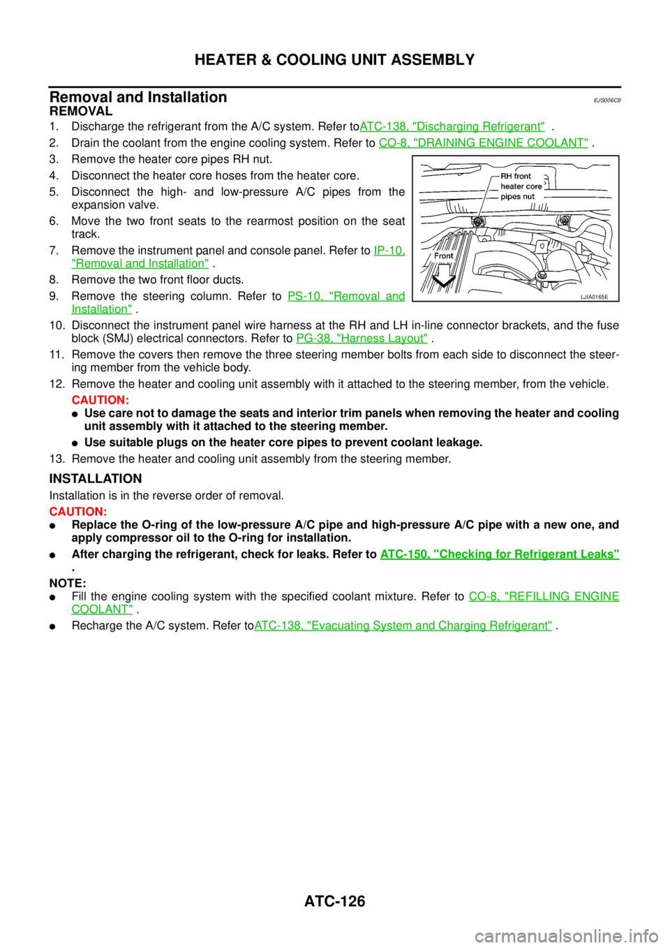
3. Remove the heater core pipes RH nut.
4. Disconnect the heater core hoses from the heater core.
5. Disconnect the high- and low-pressure A/C pipes from the
expansion valve.
6. Move the two front seats to the rearmost position on the seat
track.
7. Remove the instrument panel and console panel. Refer toIP-10,
"Removal and Installation".
8. Remove the two front floor ducts.
9. Remove the steering column. Refer toPS-10, "
Removal and
Installation".
10. Disconnect the instrument panel wire harness at the RH and LH in-line connector brackets, and the fuse
block (SMJ) electrical connectors. Refer toPG-38, "
Harness Layout".
11. Remove the covers then remove the three steering member bolts from each side to disconnect the steer-
ing member from the vehicle body.
12. Remove the heater and cooling unit assembly with it attached to the steering member, from the vehicle.
CAUTION:
lUse care not to damage the seats and interior trim panels when removing the heater and cooling
unit assembly with it attached to the steering member.
lUse suitable plugs on the heater core pipes to prevent coolant leakage.
13. Remove the heater and cooling unit assembly from the steering member.
INSTALLATION
Installation is in the reverse order of removal.
CAUTION:
lReplace the O-ring of the low-pressure A/C pipe and high-pressure A/C pipe with a new one, and
apply compressor oil to the O-ring for installation.
lAfter charging the refrigerant, check for leaks. Refer toATC-150, "Checking for Refrigerant Leaks"
.
NOTE:
lFill the engine cooling system with the specified coolant mixture. Refer toCO-8, "REFILLING ENGINE
COOLANT".
lRecharge the A/C system. Refer toATC-138, "Evacuating System and Charging Refrigerant".
LJIA0165E
Page 461 of 3171
HEATER CORE
ATC-127
C
D
E
F
G
H
I
K
L
MA
B
AT C
HEATER COREPFP:27140
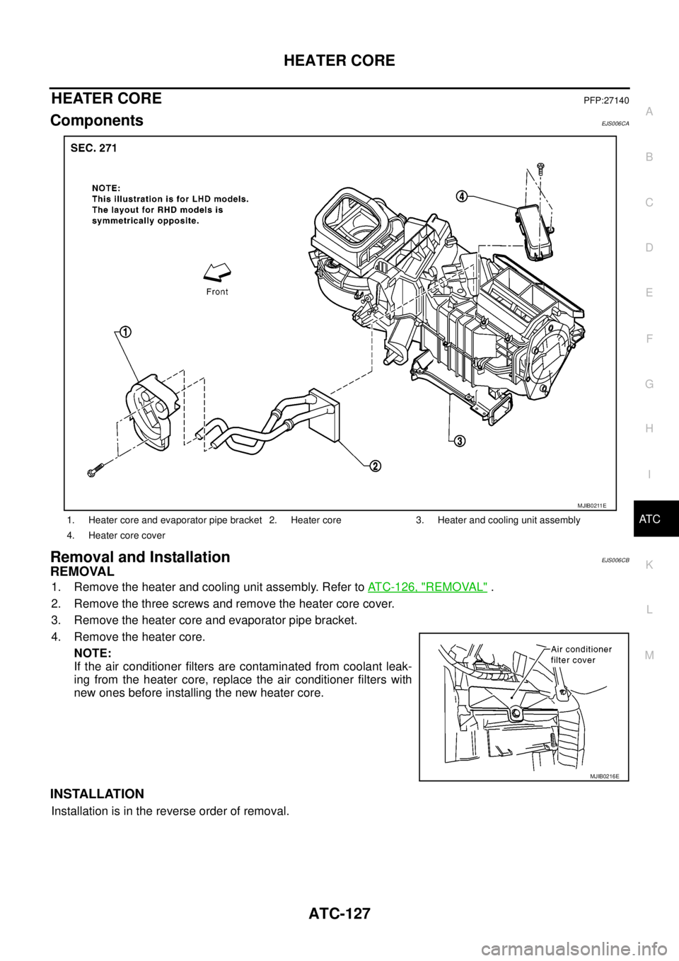
ComponentsEJS006CA
Removal and InstallationEJS006CB
REMOVAL
1. Remove the heater and cooling unit assembly. Refer toATC-126, "REMOVAL".
2. Remove the three screws and remove the heater core cover.
3. Remove the heater core and evaporator pipe bracket.
4. Remove the heater core.
NOTE:
If the air conditioner filters are contaminated from coolant leak-
ing from the heater core, replace the air conditioner filters with
new ones before installing the new heater core.
INSTALLATION
Installation is in the reverse order of removal.
1. Heater core and evaporator pipe bracket 2. Heater core 3. Heater and cooling unit assembly
4. Heater core cover
MJIB0211E
MJIB0216E
Page 885 of 3171
CO-1
ENGINE COOLING SYSTEM
B ENGINE
CONTENTS
C
D
E
F
G
H
I
J
K
L
M
SECTIONCO
A
CO
ENGINE COOLING SYSTEM
PRECAUTIONS .......................................................... 2
Precautions For Liquid Gasket ................................. 2
LIQUID GASKET APPLICATION PROCEDURE..... 2
PREPARATION ........................................................... 3
Special Service Tools ............................................... 3
Commercial Service Tools ........................................ 3
OVERHEATING CAUSE ANALYSIS .......................... 4
Troubleshooting Chart .............................................. 4
COOLING SYSTEM .................................................... 6
Cooling Circuit .......................................................... 6
ENGINE COOLANT .................................................... 7
Inspection ................................................................. 7
LEVEL CHECK ..................................................... 7
CHECKING RADIATOR SYSTEM FOR LEAKS..... 7
Changing Engine Coolant ........................................ 7
DRAINING ENGINE COOLANT ........................... 8
REFILLING ENGINE COOLANT .......................... 8
FLUSHING COOLING SYSTEM ........................... 9
RADIATOR .................................................................11
Components ............................................................ 11
Removal and Installation ......................................... 11
REMOVAL ............................................................ 11
INSPECTION AFTER REMOVAL ....................... 13
INSTALLATION ................................................... 14
INSPECTION AFTER INSTALLATION ............... 14
RADIATOR (ALUMINUM TYPE) .............................. 15
Components ........................................................... 15
Disassembly and Assembly ................................... 15
PREPARATION ................................................... 15
DISASSEMBLY ................................................... 15
ASSEMBLY ......................................................... 16
INSPECTION ...................................................... 18COOLING FAN .......................................................... 19
Components (Crankshaft Driven Type) .................. 19
Removal and Installation ........................................ 19
REMOVAL ........................................................... 19
INSPECTION AFTER REMOVAL ....................... 19
INSTALLATION ................................................... 19
Removal and Installation (Motor Driven Type) (Mod-
els with A/C) ........................................................... 19
REMOVAL ........................................................... 19
INSTALLATION ................................................... 20
WATER PUMP .......................................................... 21
Components ........................................................... 21
Removal and Installation ........................................ 21
REMOVAL ........................................................... 21
INSPECTION AFTER REMOVAL ....................... 22
INSTALLATION ................................................... 22
INSPECTION AFTER INSTALLATION ................ 22
THERMOSTAT AND WATER PIPING ...................... 23
Components ........................................................... 23
Removal and Installation ........................................ 24
REMOVAL ........................................................... 24
INSPECTION AFTER REMOVAL ....................... 24
INSTALLATION ................................................... 24
INSPECTION AFTER INSTALLATION ................ 25
SERVICE DATA AND SPECIFICATIONS (SDS) ...... 26
Standard and Limit .................................................. 26
ENGINE COOLANT CAPACITY .......................... 26
THERMOSTAT .................................................... 26
RESERVOIR TANK ............................................. 26
Page 888 of 3171
CO-4
OVERHEATING CAUSE ANALYSIS
OVERHEATING CAUSE ANALYSIS
PFP:00012
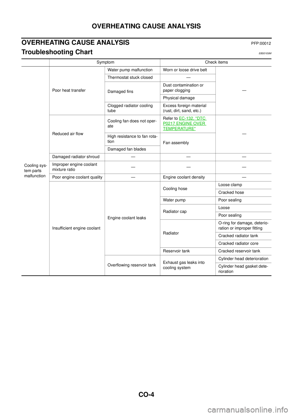
Troubleshooting ChartEBS01E6M
Symptom Check items
Cooling sys-
tem parts
malfunctionPoor heat transferWater pump malfunction Worn or loose drive belt
— Thermostat stuck closed —
Damaged finsDust contamination or
paper clogging
Physical damage
Clogged radiator cooling
tubeExcess foreign material
(rust, dirt, sand, etc.)
Reduced air flowCooling fan does not oper-
ateRefer toEC-132, "
DTC
P0217 ENGINE OVER
TEMPERATURE"
—
Highresistancetofanrota-
tion
Fan assembly
Damaged fan blades
Damaged radiator shroud — — —
Improper engine coolant
mixture ratio—— —
Poor engine coolant quality — Engine coolant density —
Insufficient engine coolantEngine coolant leaksCooling hoseLoose clamp
Cracked hose
Water pump Poor sealing
Radiator capLoose
Poor sealing
RadiatorO-ring for damage, deterio-
ration or improper fitting
Cracked radiator tank
Cracked radiator core
Reservoir tank Cracked reservoir tank
Overflowing reservoir tankExhaust gas leaks into
cooling systemCylinder head deterioration
Cylinder head gasket dete-
rioration
Page 891 of 3171
ENGINE COOLANT
CO-7
C
D
E
F
G
H
I
J
K
L
MA
CO
ENGINE COOLANTPFP:KQ100
InspectionEBS01E6P
LEVEL CHECK
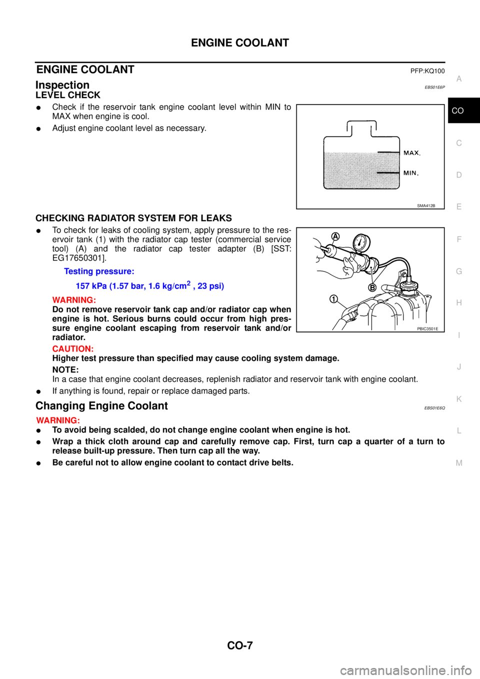
lCheck if the reservoir tank engine coolant level within MIN to
MAX when engine is cool.
lAdjust engine coolant level as necessary.
CHECKING RADIATOR SYSTEM FOR LEAKS
lTo check for leaks of cooling system, apply pressure to the res-
ervoir tank (1) with the radiator cap tester (commercial service
tool) (A) and the radiator cap tester adapter (B) [SST:
EG17650301].
WARNING:
Do not remove reservoir tank cap and/or radiator cap when
engine is hot. Serious burns could occur from high pres-
sure engine coolant escaping from reservoir tank and/or
radiator.
CAUTION:
Higher test pressure than specified may cause cooling system damage.
NOTE:
In a case that engine coolant decreases, replenish radiator and reservoir tank with engine coolant.
lIf anything is found, repair or replace damaged parts.
Changing Engine CoolantEBS01E6Q
WARNING:
lTo avoid being scalded, do not change engine coolant when engine is hot.
lWrap a thick cloth around cap and carefully remove cap. First, turn cap a quarter of a turn to
release built-up pressure. Then turn cap all the way.
lBe careful not to allow engine coolant to contact drive belts.
SMA412B
Testing pressure:
157 kPa (1.57 bar, 1.6 kg/cm
2,23psi)
PBIC3501E
Page 893 of 3171
ENGINE COOLANT
CO-9
C
D
E
F
G
H
I
J
K
L
MA
CO
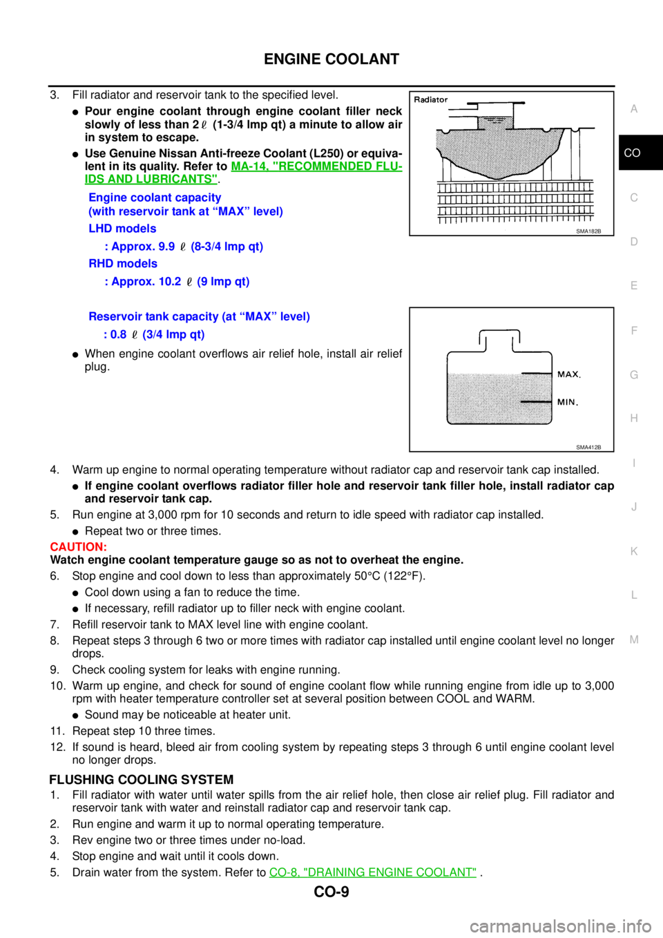
3. Fill radiator and reservoir tank to the specified level.
lPour engine coolant through engine coolant filler neck
slowly of less than 2 (1-3/4 lmp qt) a minute to allow air
in system to escape.
lUse Genuine Nissan Anti-freeze Coolant (L250) or equiva-
lent in its quality. Refer toMA-14, "
RECOMMENDED FLU-
IDS AND LUBRICANTS".
lWhen engine coolant overflows air relief hole, install air relief
plug.
4. Warm up engine to normal operating temperature without radiator cap and reservoir tank cap installed.
lIf engine coolant overflows radiator filler hole and reservoir tank filler hole, install radiator cap
and reservoir tank cap.
5. Run engine at 3,000 rpm for 10 seconds and return to idle speed with radiator cap installed.
lRepeat two or three times.
CAUTION:
Watch engine coolant temperature gauge so as not to overheat the engine.
6. Stop engine and cool down to less than approximately 50°C(122°F).
lCool down using a fan to reduce the time.
lIf necessary, refill radiator up to filler neck with engine coolant.
7. Refill reservoir tank to MAX level line with engine coolant.
8. Repeat steps 3 through 6 two or more times with radiator cap installed until engine coolant level no longer
drops.
9. Check cooling system for leaks with engine running.
10. Warm up engine, and check for sound of engine coolant flow while running engine from idle up to 3,000
rpm with heater temperature controller set at several position between COOL and WARM.
lSound may be noticeable at heater unit.
11. Repeat step 10 three times.
12. If sound is heard, bleed air from cooling system by repeating steps 3 through 6 until engine coolant level
no longer drops.
FLUSHING COOLING SYSTEM
1. Fill radiator with water until water spills from the air relief hole, then close air relief plug. Fill radiator and
reservoir tank with water and reinstall radiator cap and reservoir tank cap.
2. Run engine and warm it up to normal operating temperature.
3. Rev engine two or three times under no-load.
4. Stop engine and wait until it cools down.
5. Drain water from the system. Refer toCO-8, "
DRAINING ENGINE COOLANT". Engine coolant capacity
(with reservoir tank at “MAX” level)
LHD models
: Approx. 9.9 (8-3/4 lmp qt)
RHD models
: Approx. 10.2 (9 lmp qt)
SMA182B
Reservoir tank capacity (at “MAX” level)
: 0.8 (3/4 lmp qt)
SMA412B
Page 896 of 3171
CO-12
RADIATOR
3. Remove engine cover. Refer toEM-20, "INTAKE MANIFOLD".
4. Remove air inlet hoses between engine to charge air cooler. Refer toEM-18, "
CHARGE AIR COOLER".
5. Disconnect radiator hose (upper and lower) and reservoir tank hose.
CAUTION:
Be careful not to allow engine coolant to contact drive belts.
6. Remove reservoir tank.
7. Remove cooling fans (crankshaft driven type and motor driven type) and radiator shrouds (upper and
lower). Refer toCO-19, "
COOLING FAN".
8. Disconnect A/T fluid cooler hoses. (A/T models)
lInstall blind plug to avoid leakage of A/T fluid.
9. Remove radiator mounting brackets.
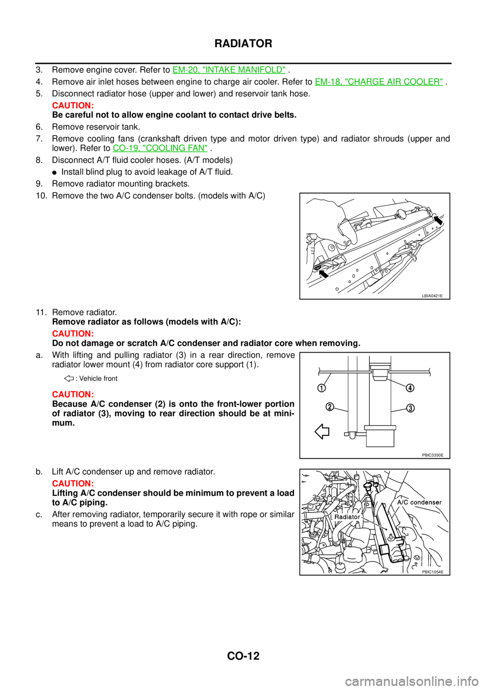
10. Remove the two A/C condenser bolts. (models with A/C)
11. Remove radiator.
Remove radiator as follows (models with A/C):
CAUTION:
Do not damage or scratch A/C condenser and radiator core when removing.
a. With lifting and pulling radiator (3) in a rear direction, remove
radiator lower mount (4) from radiator core support (1).
CAUTION:
Because A/C condenser (2) is onto the front-lower portion
of radiator (3), moving to rear direction should be at mini-
mum.
b. Lift A/C condenser up and remove radiator.
CAUTION:
Lifting A/C condenser should be minimum to prevent a load
to A/C piping.
c. After removing radiator, temporarily secure it with rope or similar
means to prevent a load to A/C piping.
LBIA0421E
: Vehicle front
PBIC3350E
PBIC1054E
Page 898 of 3171
![NISSAN NAVARA 2005 Repair Workshop Manual CO-14
RADIATOR
INSTALLATION
Installation is the reverse order of removal.
INSPECTION AFTER INSTALLATION
lCheck for leaks of engine coolant using the radiator cap tester adapter [SST: EG17650301] and t NISSAN NAVARA 2005 Repair Workshop Manual CO-14
RADIATOR
INSTALLATION
Installation is the reverse order of removal.
INSPECTION AFTER INSTALLATION
lCheck for leaks of engine coolant using the radiator cap tester adapter [SST: EG17650301] and t](/manual-img/5/57362/w960_57362-897.png)
CO-14
RADIATOR
INSTALLATION
Installation is the reverse order of removal.
INSPECTION AFTER INSTALLATION
lCheck for leaks of engine coolant using the radiator cap tester adapter [SST: EG17650301] and the radia-
tor cap tester (commercial service tool). Refer toCO-7, "
CHECKING RADIATOR SYSTEM FOR LEAKS".
lStart and warm up engine. Visually check if there is no leaks of engine coolant.