2005 NISSAN NAVARA run flat
[x] Cancel search: run flatPage 560 of 3171

AV-72
TROUBLE DIAGNOSIS
–Because calculation of the current location cannot be done when traveling with the ignition OFF, for exam-
ple when traveling by ferry or when being towed, the location before travel is displayed. If the precise loca-
tioncanbedetectedwithGPS,thelocationwillbecorrected.
THE CURRENT POSITION MARK JUMPS.
In the following cases, the current location mark may appear to jump as a result of automatic correction of the
current location.
lWhen map matching has been done
–If current location and the current location mark are different when map matching is done, the current
location mark may seem to jump. At this time, the location may be “corrected” to the incorrect road or to a
location which is not on a road.
lWhen GPS location correction has been done
–If current location and the current location mark are different when location is corrected using GPS mea-
surements, the current location mark may seem to jump. At this time, the location may be “corrected” to a
location which is not on a road.
THE CURRENT LOCATION MARK IS IN A RIVER OR THE SEA.
The navigation system moves the current location mark with no distinction between land and rivers or sea. If
the location mark is somehow out of place, it may appear that the vehicle is driving in a river or the sea.
CURRENT LOCATION MARK ROTATES WITHOUT OPERATION
If the ignition switch is turned ON with the turntable rotating, the rotating condition is recorded as the stop con-
dition. Therefore, the current location mark might rotate when actually stopping.
WHEN DRIVING ON THE SAME ROAD, SOMETIMES THE CURRENT LOCATION MARK IS IN
THE CORRECT PLACE AND SOMETIMES IT IS IN THE INCORRECT PLACE.
The conditions of the GPS antenna (GPS data) and gyroscope (angular speed sensor) change gradually.
Depending on the road traveled and operation of the steering wheel, the location detection results will be dif-
ferent. Therefore, even on a road on which the location has never been incorrect, conditions may cause the
vehicle mark to deviate.
LOCATION CORRECTION BY MAP MATCHING IS SLOW.
lThe map matching function needs to refer to the data of the surrounding area. It is necessary to drive
some distance for the function to work.
lBecause of the way map matching operates, when there are many roads running in similar directions in
the surrounding area a matching determination may be impossible. The location will remain uncorrected
until some special feature is found.
ALTHOUGH THE GPS RECEIVING DISPLAY IS GREEN, THE VEHICLE MARK DOES NOT
RETURN TO THE CORRECT LOCATION.
lGPS accuracy has a malfunction range of about 10 m. In some cases the current location mark may not
be on the correct street, even when GPS location correction is done.
lThe navigation system compares the results of GPS location detection with the results from map-match-
ing location detection. The one that is determined to have higher accuracy is used.
lPosition correction by GPS is not available while the vehicle is stopped.
THE NAME OF THE CURRENT PLACE IS NOT DISPLAYED.
The current place name might not be displayed when there is no name of place information in the map screen.
THE DISPLAY IS DIFFERENT BETWEEN BIRDVIEW®AND (FLAT) MAP DISPLAY.
The following is different at birdview®.
lThe current place name displays names that are primarily in the direction of vehicle travel.
lThe amount of time before the vehicle travel or turn angle is updated on the screen is longer than for the
(flat) map display.
lThe conditions for display of place names, roads, and other data are different for nearby areas and for
more distant areas.
lSome trimming of the character data is done to prevent the display from becoming too complex. In some
cases and in some locations, the display contents may differ.
lThe same place name, street name, etc. may be displayed multiple times.
Page 990 of 3171

EC-10
PRECAUTIONS
PRECAUTIONS
PFP:00001
Precautions for Supplemental Restraint System (SRS) “AIR BAG” and “SEAT
BELT PRE-TENSIONER”
EBS01KC5
The Supplemental Restraint System such as “AIR BAG” and “SEAT BELT PRE-TENSIONER”, used along
with a front seat belt, helps to reduce the risk or severity of injury to the driver and front passenger for certain
types of collision. Information necessary to service the system safely is included in the SRS and SB section of
this Service Manual.
WARNING:
lTo avoid rendering the SRS inoperative, which could increase the risk of personal injury or death
in the event of a collision which would result in air bag inflation, all maintenance must be per-
formed by an authorized NISSAN/INFINITI dealer.
lImproper maintenance, including incorrect removal and installation of the SRS, can lead to per-
sonal injury caused by unintentional activation of the system. For removal of Spiral Cable and Air
Bag Module, see the SRS section.
lDo not use electrical test equipment on any circuit related to the SRS unless instructed to in this
Service Manual. SRS wiring harnesses can be identified by yellow and/or orange harnesses or
harness connectors.
On Board Diagnostic (OBD) System of EngineEBS01KC6
The ECM has an on board diagnostic system. It will light up the malfunction indicator (MI) to warn the driver of
a malfunction causing emission deterioration.
CAUTION:
lBe sure to turn the ignition switch OFF and disconnect the battery negative cable before any
repair or inspection work. The open/short circuit of related switches, sensors, solenoid valves,
etc. will cause the MI to light up.
lBe sure to connect and lock the connectors securely after work. A loose (unlocked) connector will
cause the MI to light up due to the open circuit. (Be sure the connector is free from water, grease,
dirt, bent terminals, etc.)
lCertain systems and components, especially those related to OBD, may use a new style slide-
locking type harness connector. For description and how to disconnect, refer toPG-75, "
HAR-
NESS CONNECTOR".
lBe sure to route and secure the harnesses properly after work. The interference of the harness
with a bracket, etc. may cause the MI to light up due to the short circuit.
lBe sure to connect rubber tubes properly after work. A misconnected or disconnected rubber tube
may cause the MI to light up due to the malfunction of the fuel system, etc.
lBe sure to erase the unnecessary malfunction information (repairs completed) from the ECM
before returning the vehicle to the customer.
PrecautionsEBS01KC7
lAlways use a 12 volt battery as power source.
lDo not attempt to disconnect battery cables while engine is
running.
lBefore connecting or disconnecting the ECM harness con-
nector, turn ignition switch OFF and disconnect battery
negative cable. Failure to do so may damage the ECM
because battery voltage is applied to ECM even if ignition
switch is turned off.
lBefore removing parts, turn ignition switch OFF and then
disconnect battery negative cable.
SEF289H
Page 1443 of 3171

CAMSHAFT
EM-61
C
D
E
F
G
H
I
J
K
L
MA
EM
Camshaft Runout
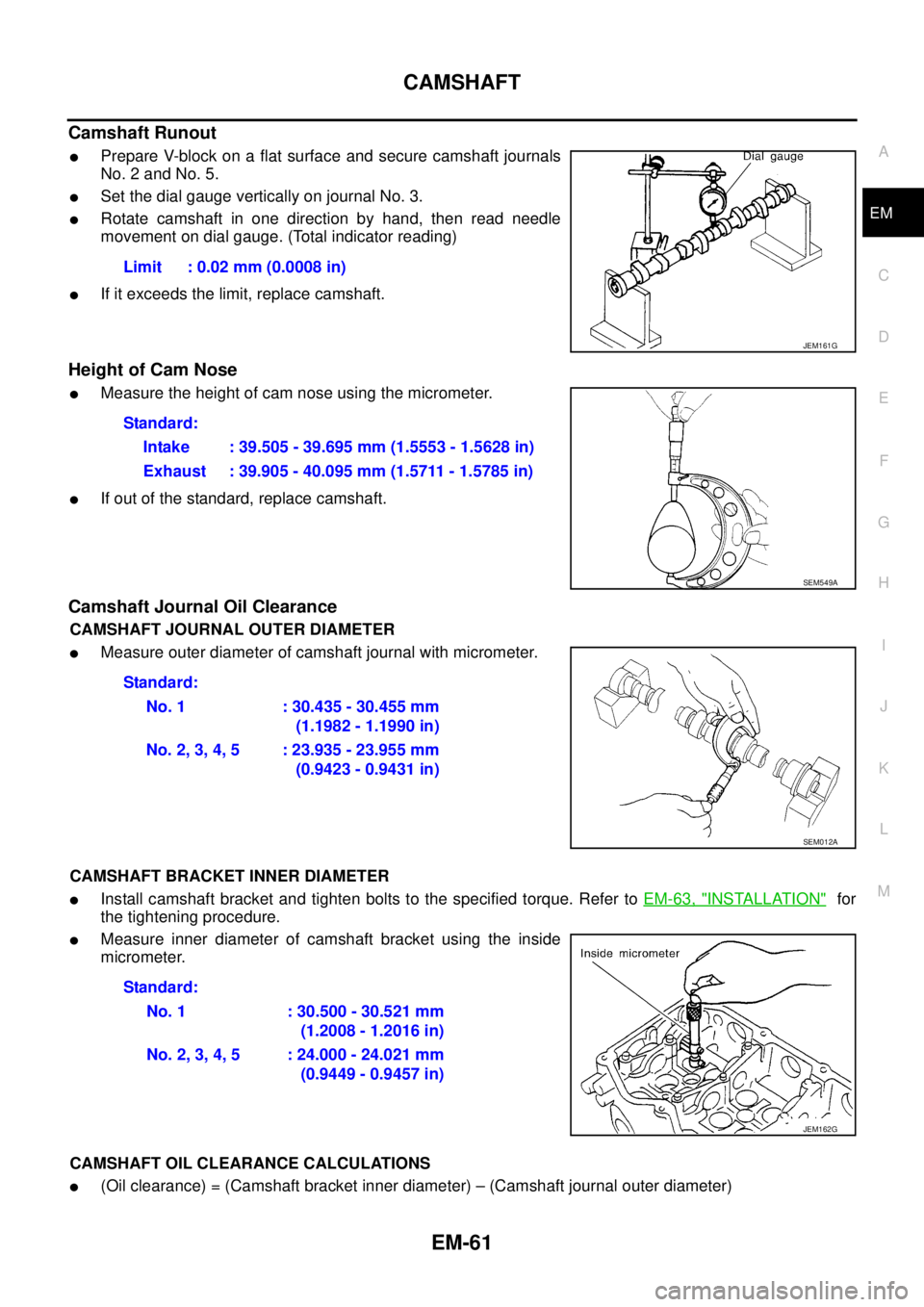
lPrepare V-block on a flat surface and secure camshaft journals
No. 2 and No. 5.
lSet the dial gauge vertically on journal No. 3.
lRotate camshaft in one direction by hand, then read needle
movement on dial gauge. (Total indicator reading)
lIf it exceeds the limit, replace camshaft.
Height of Cam Nose
lMeasure the height of cam nose using the micrometer.
lIf out of the standard, replace camshaft.
Camshaft Journal Oil Clearance
CAMSHAFT JOURNAL OUTER DIAMETER
lMeasure outer diameter of camshaft journal with micrometer.
CAMSHAFT BRACKET INNER DIAMETER
lInstall camshaft bracket and tighten bolts to the specified torque. Refer toEM-63, "INSTALLATION"for
the tightening procedure.
lMeasure inner diameter of camshaft bracket using the inside
micrometer.
CAMSHAFT OIL CLEARANCE CALCULATIONS
l(Oil clearance) = (Camshaft bracket inner diameter) – (Camshaft journal outer diameter)Limit : 0.02 mm (0.0008 in)
JEM161G
Standard:
Intake : 39.505 - 39.695 mm (1.5553 - 1.5628 in)
Exhaust : 39.905 - 40.095 mm (1.5711 - 1.5785 in)
SEM549A
Standard:
No. 1 : 30.435 - 30.455 mm
(1.1982 - 1.1990 in)
No.2,3,4,5 :23.935-23.955mm
(0.9423 - 0.9431 in)
SEM012A
Standard:
No. 1 : 30.500 - 30.521 mm
(1.2008 - 1.2016 in)
No.2,3,4,5 :24.000-24.021mm
(0.9449 - 0.9457 in)
JEM162G
Page 1607 of 3171

ON-VEHICLE SERVICE
FSU-7
C
D
F
G
H
I
J
K
L
MA
B
FSU
ON-VEHICLE SERVICEPFP:00000
Front Suspension PartsEES002KM
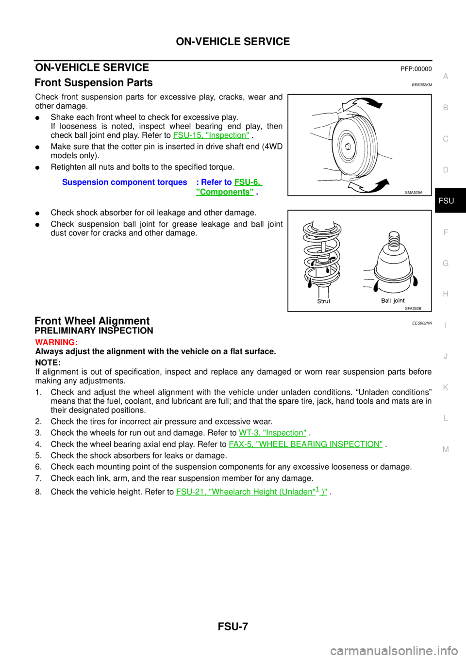
Check front suspension parts for excessive play, cracks, wear and
other damage.
lShake each front wheel to check for excessive play.
If looseness is noted, inspect wheel bearing end play, then
check ball joint end play. Refer toFSU-15, "
Inspection".
lMake sure that the cotter pin is inserted in drive shaft end (4WD
models only).
lRetighten all nuts and bolts to the specified torque.
lCheck shock absorber for oil leakage and other damage.
lCheck suspension ball joint for grease leakage and ball joint
dust cover for cracks and other damage.
Front Wheel AlignmentEES002KN
PRELIMINARY INSPECTION
WARNING:
Always adjust the alignment with the vehicle on a flat surface.
NOTE:
If alignment is out of specification, inspect and replace any damaged or worn rear suspension parts before
making any adjustments.
1. Check and adjust the wheel alignment with the vehicle under unladen conditions. “Unladen conditions”
means that the fuel, coolant, and lubricant are full; and that the spare tire, jack, hand tools and mats are in
their designated positions.
2. Check the tires for incorrect air pressure and excessive wear.
3. Check the wheels for run out and damage. Refer toWT-3, "
Inspection".
4. Check the wheel bearing axial end play. Refer toFA X - 5 , "
WHEEL BEARING INSPECTION".
5. Check the shock absorbers for leaks or damage.
6. Check each mounting point of the suspension components for any excessive looseness or damage.
7. Check each link, arm, and the rear suspension member for any damage.
8. Check the vehicle height. Refer toFSU-21, "
Wheelarch Height (Unladen*1)". Suspension component torques : Refer toFSU-6,
"Components".SMA525A
SFA392B
Page 2736 of 3171
![NISSAN NAVARA 2005 Repair Workshop Manual PRECAUTIONS
RFD-33
[WITH ELECTRONIC LOCKING DIFFERENTIAL]
C
E
F
G
H
I
J
K
L
MA
B
RFD
[WITH ELECTRONIC LOCKING DIFFERENTIAL]PRECAUTIONSPFP:00001
Precautions for Supplemental Restraint System (SRS) “A NISSAN NAVARA 2005 Repair Workshop Manual PRECAUTIONS
RFD-33
[WITH ELECTRONIC LOCKING DIFFERENTIAL]
C
E
F
G
H
I
J
K
L
MA
B
RFD
[WITH ELECTRONIC LOCKING DIFFERENTIAL]PRECAUTIONSPFP:00001
Precautions for Supplemental Restraint System (SRS) “A](/manual-img/5/57362/w960_57362-2735.png)
PRECAUTIONS
RFD-33
[WITH ELECTRONIC LOCKING DIFFERENTIAL]
C
E
F
G
H
I
J
K
L
MA
B
RFD
[WITH ELECTRONIC LOCKING DIFFERENTIAL]PRECAUTIONSPFP:00001
Precautions for Supplemental Restraint System (SRS) “AIR BAG” and “SEAT
BELT PRE-TENSIONER”
EDS003IE
The Supplemental Restraint System such as “AIR BAG” and “SEAT BELT PRE-TENSIONER”, used along
with a front seat belt, helps to reduce the risk or severity of injury to the driver and front passenger for certain
types of collision. Information necessary to service the system safely is included in the SRS and SB section of
this Service Manual.
WARNING:
lTo avoid rendering the SRS inoperative, which could increase the risk of personal injury or death
in the event of a collision which would result in air bag inflation, all maintenance must be per-
formed by an authorized NISSAN/INFINITI dealer.
lImproper maintenance, including incorrect removal and installation of the SRS, can lead to per-
sonal injury caused by unintentional activation of the system. For removal of Spiral Cable and Air
Bag Module, see the SRS section.
lDo not use electrical test equipment on any circuit related to the SRS unless instructed to in this
Service Manual. SRS wiring harnesses can be identified by yellow and/or orange harnesses or
harness connectors.
Precautions for Differential Case Assembly and Differential Lock Control Unit
Replacement
EDS003AG
lWhen replacing differential case assembly or differential lock control unit, check the DIFF LOCK indicator
pattern and adjustment of the position between differential case assembly and differential lock control unit
if necessary.
CHECK DIFF LOCK INDICATOR LAMP
1. Start engine. Run engine for at least 10 seconds.
2. Turn 4WD shift switch to “4LO” and confirm 4LO indicator lamp is turned on. Refer toTF-16, "
4WD SHIFT
SWITCH AND INDICATOR LAMP".
3. Stop vehicle and turn differential lock mode switch to “ON”.
4. Drive vehicle at 7 km/h (4 MPH) or less.
NOTE:
Differential case assembly must be given a rotation from rear left wheel and rear right wheel.
5. Check if DIFF LOCK indicator lamp flashes to turn on.
6. Check if DIFF LOCK indicator lamp and 4LO indicator lamp are changed properly as follows.
lIf each indication and state is OK, rear final drive assembly and differential lock control unit is working cor-
rectly.
lIf each indication and state is NG, rear final drive assembly and differential lock control unit is not working
correctly. Refer toRFD-34, "
METHOD FOR ADJUSTMENT".
Differential lock mode
switch4LO indicator lamp Vehicle speed (VSS)Differential case assem-
bly stateDIFF LOCK indicator
lamp
ONOFF7 km/h (4 MPH) < VSS
Disengage Flash VSS£7km/h(4MPH)
ON7 km/h (4 MPH) < VSS
VSS£7 km/h (4 MPH) Disengage®Engage Flash®ON
OFFOFF7 km/h (4 MPH) < VSS
Disengage OFF VSS£7km/h(4MPH)
ON7 km/h (4 MPH) < VSS
VSS£7km/h(4MPH)
Page 3108 of 3171

WHEEL
WT-3
C
D
F
G
H
I
J
K
L
MA
B
WT
WHEELPFP:40300
InspectionEES002L2
1. Check tires for wear and improper inflation.
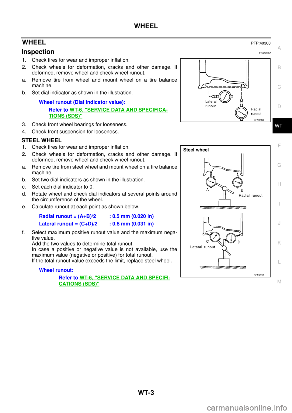
2. Check wheels for deformation, cracks and other damage. If
deformed, remove wheel and check wheel runout.
a. Remove tire from wheel and mount wheel on a tire balance
machine.
b. Set dial indicator as shown in the illustration.
3. Check front wheel bearings for looseness.
4. Check front suspension for looseness.
STEEL WHEEL
1. Check tires for wear and improper inflation.
2. Check wheels for deformation, cracks and other damage. If
deformed, remove wheel and check wheel runout.
a. Remove tire from steel wheel and mount wheel on a tire balance
machine.
b. Set two dial indicators as shown in the illustration.
c. Set each dial indicator to 0.
d. Rotate wheel and check dial indicators at several points around
the circumference of the wheel.
e. Calculate runout at each point as shown below.
f. Select maximum positive runout value and the maximum nega-
tive value.
Add the two values to determine total runout.
In case a positive or negative value is not available, use the
maximum value (negative or positive) for total runout.
If the total runout value exceeds the limit, replace steel wheel.Wheel runout (Dial indicator value):
Refer toWT-6, "
SERVICE DATA AND SPECIFICA-
TIONS (SDS)"SFA975B
Radial runout = (A+B)/2 : 0.5 mm (0.020 in)
Lateral runout = (C+D)/2 : 0.8 mm (0.031 in)
Wheel runout:
Refer toWT-6, "
SERVICE DATA AND SPECIFI-
CATIONS (SDS)"
SFA981B