Page 174 of 3171

AT-166
MAIN POWER SUPPLY AND GROUND CIRCUIT
3.DETECT MALFUNCTIONING ITEM
Check the following.
lHarness for short or open between battery and A/T assembly harness connector F36 terminals 1, 2
lHarness for short or open between ignition switch and A/T assembly harness connector F36 terminal 6
l10A fuse (No. 25, located in fuse and fusible link block) and 10A fuse (No. 49, located in IPDM E/R)
lIgnition switch, Refer toPG-4, "POWER SUPPLY ROUTING CIRCUIT".
OK or NG
OK >> GO TO 4.
NG >> Repair or replace damaged parts.
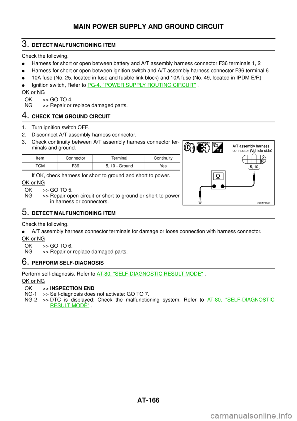
4.CHECK TCM GROUND CIRCUIT
1. Turn ignition switch OFF.
2. Disconnect A/T assembly harness connector.
3. Check continuity between A/T assembly harness connector ter-
minals and ground.
If OK, check harness for short to ground and short to power.
OK or NG
OK >> GO TO 5.
NG >> Repair open circuit or short to ground or short to power
in harness or connectors.
5.DETECT MALFUNCTIONING ITEM
Check the following.
lA/T assembly harness connector terminals for damage or loose connection with harness connector.
OK or NG
OK >> GO TO 6.
NG >> Repair or replace damaged parts.
6.PERFORM SELF-DIAGNOSIS
Perform self-diagnosis. Refer toAT-80, "
SELF-DIAGNOSTIC RESULT MODE".
OK or NG
OK >>INSPECTION END
NG-1 >> Self-diagnosis does not activate: GO TO 7.
NG-2 >> DTC is displayed: Check the malfunctioning system. Refer toAT-80, "
SELF-DIAGNOSTIC
RESULT MODE".
Item Connector Terminal Continuity
TCM F36 5, 10 - Ground Yes
SCIA2106E
Page 177 of 3171

BRAKE SIGNAL CIRCUIT
AT-169
D
E
F
G
H
I
J
K
L
MA
B
AT
BRAKE SIGNAL CIRCUITPFP:25320
CONSULT-II Reference ValueECS00G26
Diagnostic ProcedureECS00G27
1.CHECK CAN COMMUNICATION LINE
Perform self-diagnosis. Refer toAT-80, "
SELF-DIAGNOSTIC RESULT MODE",AT-89, "Diagnostic Procedure
Without CONSULT-II".
Is a malfunction in the CAN communication indicated in the results?
YES >> Check CAN communication line. Refer toAT-91, "DTC U1000 CAN COMMUNICATION LINE".
NO >> GO TO 2.
2.CHECK STOP LAMP SWITCH CIRCUIT
With CONSULT-II
1. Turn ignition switch ON. (Do not start engine.)
2. Select “ECU INPUT SIGNALS” in “DATA MONITOR” mode for
“A/T” with CONSULT-II.
3. Read the ON/OFF switching action of “BRAKE SW”.
OK or NG
OK >>INSPECTION END
NG >> GO TO 3.
3.CHECK STOP LAMP SWITCH
Check continuity between stop lamp switch harness connector E109
terminals 1 and 2. Refer toAT- 1 7 4 , "
Wiring Diagram—AT—NON-
DTC".
Check stop lamp switch after adjusting brake pedal — refer to
BR-6, "
BRAKE PEDAL".
OK or NG
OK >> Check the following. If NG, repair or replace damaged
parts.
lHarness for short or open between battery and stop lamp switch.
lHarness for short or open between stop lamp switch and combination meter.
l10A fuse (No.20, located in fuse block).
NG >> Repair or replace stop lamp switch.
Item name Condition Display value
BRAKE SWDepressed brake pedal. ON
Released brake pedal. OFF
Item name Condition Display value
BRAKE SWDepressed brake pedal. ON
Released brake pedal. OFF
PCIA0070E
Condition Continuity
When brake pedal is depressed Yes
When brake pedal is released No
SCIA2144E
Page 223 of 3171

A/T SHIFT LOCK SYSTEM
AT-215
D
E
F
G
H
I
J
K
L
MA
B
AT
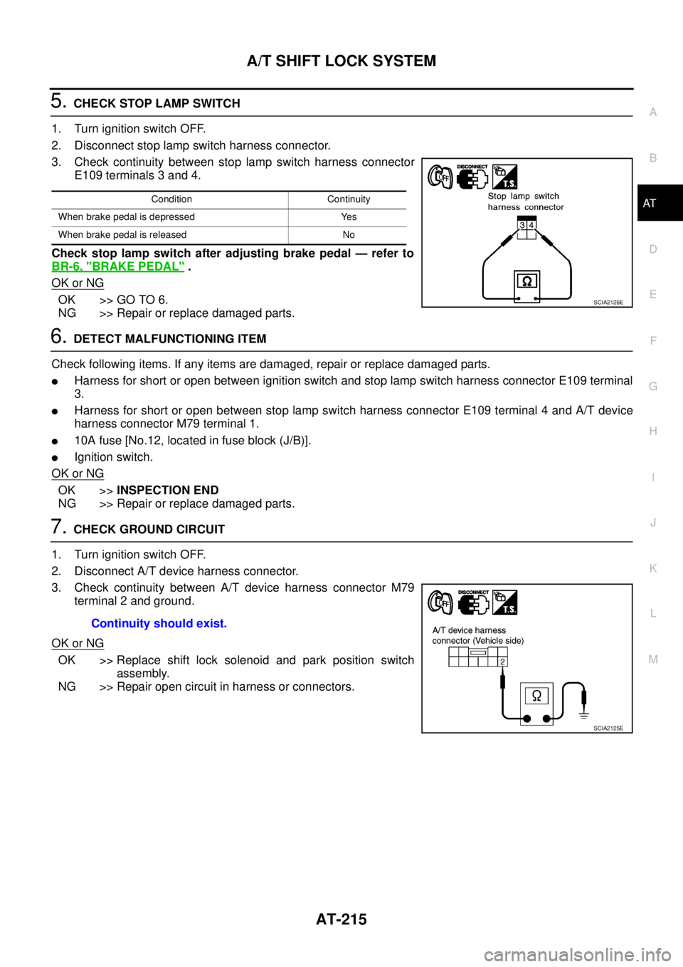
5.CHECK STOP LAMP SWITCH
1. Turn ignition switch OFF.
2. Disconnect stop lamp switch harness connector.
3. Check continuity between stop lamp switch harness connector
E109 terminals 3 and 4.
Check stop lamp switch after adjusting brake pedal — refer to
BR-6, "
BRAKE PEDAL".
OK or NG
OK >> GO TO 6.
NG >> Repair or replace damaged parts.
6.DETECT MALFUNCTIONING ITEM
Check following items. If any items are damaged, repair or replace damaged parts.
lHarness for short or open between ignition switch and stop lamp switch harness connector E109 terminal
3.
lHarness for short or open between stop lamp switch harness connector E109 terminal 4 and A/T device
harness connector M79 terminal 1.
l10A fuse [No.12, located in fuse block (J/B)].
lIgnition switch.
OK or NG
OK >>INSPECTION END
NG >> Repair or replace damaged parts.
7.CHECK GROUND CIRCUIT
1. Turn ignition switch OFF.
2. Disconnect A/T device harness connector.
3. Check continuity between A/T device harness connector M79
terminal 2 and ground.
OK or NG
OK >> Replace shift lock solenoid and park position switch
assembly.
NG >> Repair open circuit in harness or connectors.
Condition Continuity
When brake pedal is depressed Yes
When brake pedal is released No
SCIA2126E
Continuity should exist.
SCIA2125E
Page 344 of 3171
ATC-10
PRECAUTIONS
A/C Compressor and Condenser —RHD Models—
CAUTION:
The new and former refrigerant connections use different O-ring configurations. Do not confuse O-
rings since they are not interchangeable. If a wrong O-ring is installed, refrigerant will leak at or
around the connection.
MJIB0277E
1. High-pressure service valve 2. Clip 3. High-pressure A/C pipe
4. Refrigerant pressure sensor 5. Condenser 6. Compressor shaft seal
7. High-pressure flexible A/C hose 8. Low-pressure flexible A/C hose 9. Low-pressure service valve
10. Low-pressure A/C pipe 11. Expansion valve 12. A/C drain hose
Page 396 of 3171

ATC-62
TROUBLE DIAGNOSIS
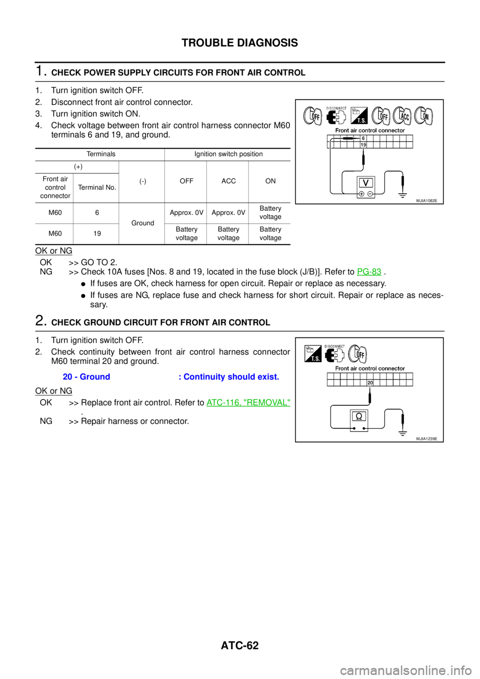
1.CHECK POWER SUPPLY CIRCUITS FOR FRONT AIR CONTROL
1. Turn ignition switch OFF.
2. Disconnect front air control connector.
3. Turn ignition switch ON.
4. Check voltage between front air control harness connector M60
terminals 6 and 19, and ground.
OK or NG
OK >> GO TO 2.
NG >> Check 10A fuses [Nos. 8 and 19, located in the fuse block (J/B)]. Refer toPG-83
.
lIf fuses are OK, check harness for open circuit. Repair or replace as necessary.
lIf fuses are NG, replace fuse and check harness for short circuit. Repair or replace as neces-
sary.
2.CHECK GROUND CIRCUIT FOR FRONT AIR CONTROL
1. Turn ignition switch OFF.
2. Check continuity between front air control harness connector
M60 terminal 20 and ground.
OK or NG
OK >> Replace front air control. Refer toAT C - 11 6 , "REMOVAL"
.
NG >> Repair harness or connector.
Terminals Ignition switch position
(+)
(-) OFF ACC ON Front air
control
connectorTerminal No.
M60 6
GroundApprox. 0V Approx. 0VBattery
voltage
M60 19Battery
voltageBattery
voltageBattery
voltage
WJIA1082E
20 - Ground : Continuity should exist.
WJIA1239E
Page 417 of 3171
![NISSAN NAVARA 2005 Repair Workshop Manual TROUBLE DIAGNOSIS
ATC-83
C
D
E
F
G
H
I
K
L
MA
B
AT C
1.CHECK FUSES
Check 15A fuses [No. 24 and 27, (located in the fuse and fusible link box)]. For fuse layout, refer toPG-84,
"FUSE AND FUSIBLE LINK B NISSAN NAVARA 2005 Repair Workshop Manual TROUBLE DIAGNOSIS
ATC-83
C
D
E
F
G
H
I
K
L
MA
B
AT C
1.CHECK FUSES
Check 15A fuses [No. 24 and 27, (located in the fuse and fusible link box)]. For fuse layout, refer toPG-84,
"FUSE AND FUSIBLE LINK B](/manual-img/5/57362/w960_57362-416.png)
TROUBLE DIAGNOSIS
ATC-83
C
D
E
F
G
H
I
K
L
MA
B
AT C
1.CHECK FUSES
Check 15A fuses [No. 24 and 27, (located in the fuse and fusible link box)]. For fuse layout, refer toPG-84,
"FUSE AND FUSIBLE LINK BOX".
OK or NG
OK >> GO TO 2.
NG >> GO TO 10.
2.CHECK BLOWER MOTOR POWER SUPPLY CIRCUIT
1. Turn ignition switch OFF.
2. Disconnect blower motor connector.
3. Turn ignition switch ON.
4. Turn the blower control dial to select any mode except off.
5. Check voltage between blower motor harness connector M94
terminal 2 and ground.
OK or NG
OK >> GO TO 12.
NG >> GO TO 3.
3.CHECK BLOWER MOTOR RELAY (SWITCH SIDE) POWER SUPPLY CIRCUIT
1. Turn ignition switch OFF.
2. Disconnect blower motor relay.
3. Check voltage between blower motor relay harness connector
E28 terminals 3 and 6 and ground.
OK or NG
OK >> GO TO 4.
NG >> Repair harness or connector.
4.CHECK BLOWER MOTOR RELAY
Refer toAT C - 8 6 , "
Blower Motor Relay".
OK or NG
OK >> GO TO 5.
NG >> Replace blower motor relay.
5.CHECK BLOWER MOTOR RELAY (SWITCH SIDE) CIRCUIT FOR OPEN
1. Turn ignition switch OFF.
2. Disconnect blower motor relay connector and blower motor con-
nector.
3. Check continuity between blower motor relay harness connector
E28 terminals 5 and 7 and blower motor harness connector M94
terminal 2.
OK or NG
OK >> GO TO 6.
NG >> Repair harness or connector.Fuses are good.
2 - Ground : Battery voltage.
MJIB0065E
3, 6 - Ground : Battery voltage.
MJIB0066E
5, 7 - 2 : Continuity should exist.
MJIB0067E
Page 419 of 3171
TROUBLE DIAGNOSIS
ATC-85
C
D
E
F
G
H
I
K
L
MA
B
AT C
10.REPLACE FUSES
1. Replace fuses.
2. Activate the blower motor.
3. Do fuses blow?
YES or NO
YES >> GO TO 11.
NO >> Inspection End.
11 .CHECK BLOWER MOTOR POWER SUPPLY CIRCUIT FOR SHORT
1. Turn ignition switch OFF.
2. Disconnect blower motor connector and variable blower control
connector.
3. Check continuity between variable blower control harness con-
nector M96 terminal 1 and ground.
OK or NG
OK >> GO TO 12.
NG >> Repair harness or connector.
12.CHECK VARIABLE BLOWER CONTROL SIGNAL CIRCUIT
1. Disconnect front air control connector.
2. Check continuity between front air control harness connector
M61 terminal 32 and variable blower control harness connector
M96 terminal 2.
OK or NG
OK >> Check blower motor. If OK, replace variable blower con-
trol. Refer toATC-121, "
REMOVAL".
NG >> Repair harness or connector.1 - Ground : Continuity should not exist.
WJIA1264E
32 - 2 : Continuity should exist.
WJIA1263E
Page 423 of 3171

TROUBLE DIAGNOSIS
ATC-89
C
D
E
F
G
H
I
K
L
MA
B
AT C
2.PERFORM AUTO ACTIVE TEST
Refer toPG-19, "
Auto Active Test".
Does magnet clutch operate?
YES or NO
YES >>lWITH CONSULT-II
GO TO 5.
lWITHOUT CONSULT-II
GO TO 6.
NO >> Check 10A fuse (No. 42, located in IPDM E/R), and GO TO 3.
3.CHECK CIRCUIT CONTINUITY BETWEEN IPDM E/R AND COMPRESSOR
1. Turn ignition switch OFF.
2. Disconnect IPDM E/R connector and compressor (magnet
clutch) connector.
3. Check continuity between IPDM E/R harness connector E12 ter-
minal 11 and compressor harness connector F20 terminal 1.
OK or NG
OK >> GO TO 4.
NG >> Repair harness or connector.
4.CHECK MAGNET CLUTCH CIRCUIT
Check for operation sound when applying battery voltage direct cur-
rent to terminal.
OK or NG
OK >> Replace IPDM E/R. Refer toPG-26, "Removal and
Installation of IPDM E/R".
NG >> Replace magnet clutch. Refer toBCS-17, "
Removal and
Installation of BCM".
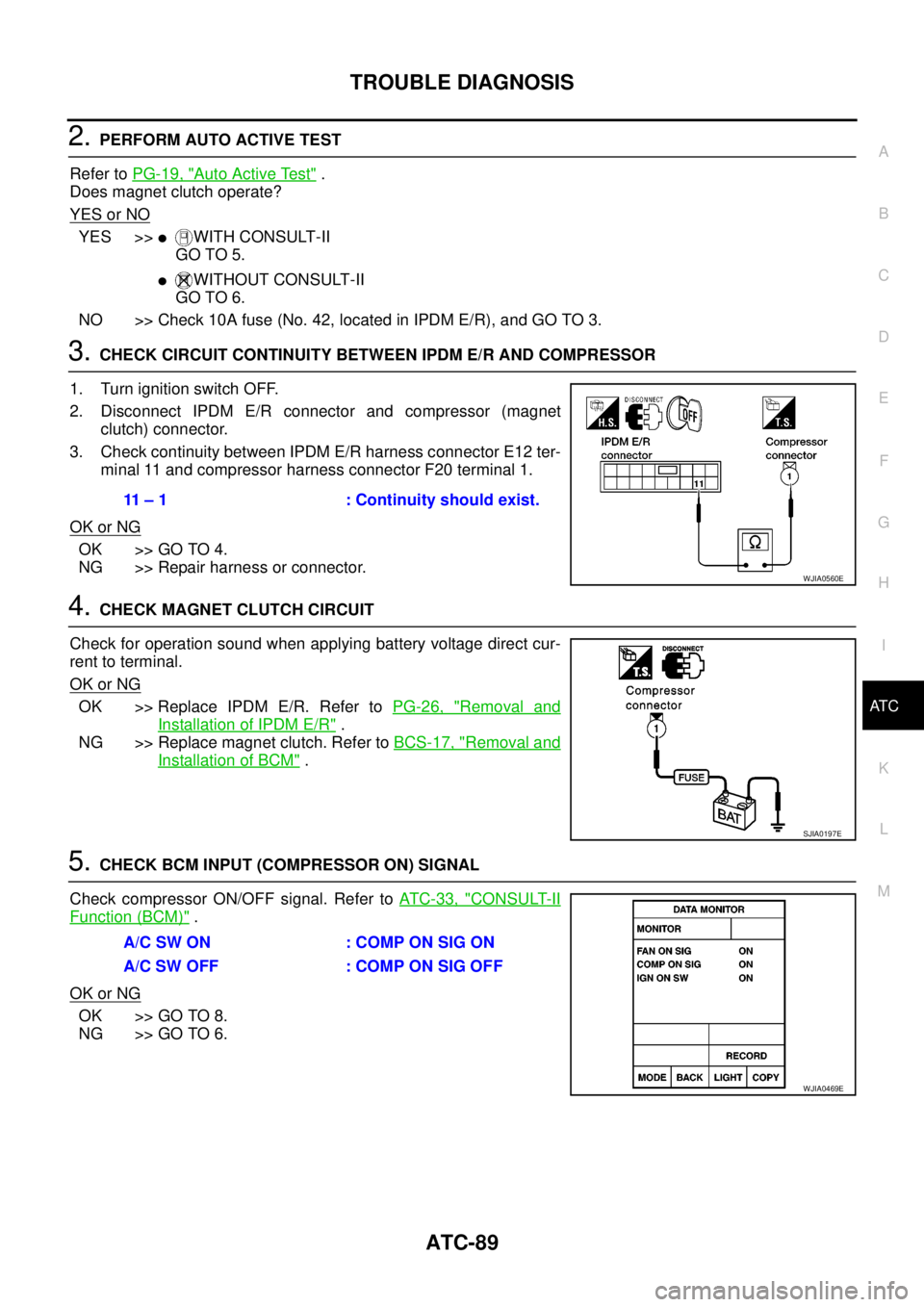
5.CHECK BCM INPUT (COMPRESSOR ON) SIGNAL
Check compressor ON/OFF signal. Refer toAT C - 3 3 , "
CONSULT-II
Function (BCM)".
OK or NG
OK >> GO TO 8.
NG >> GO TO 6.
11 – 1 : Continuity should exist.
WJIA0560E
SJIA0197E
A/C SW ON : COMP ON SIG ON
A/CSWOFF :COMPONSIGOFF
WJIA0469E