Page 460 of 3171

ATC-126
HEATER & COOLING UNIT ASSEMBLY
Removal and Installation
EJS006C9
REMOVAL
1. Discharge the refrigerant from the A/C system. Refer toATC-138, "Discharging Refrigerant".
2. Drain the coolant from the engine cooling system. Refer toCO-8, "
DRAINING ENGINE COOLANT".
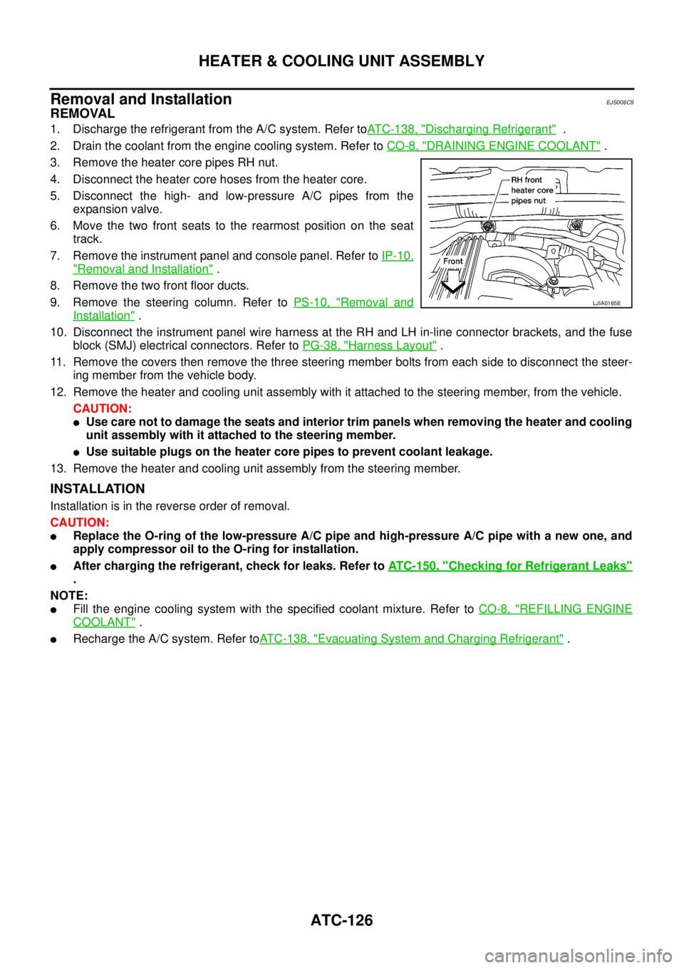
3. Remove the heater core pipes RH nut.
4. Disconnect the heater core hoses from the heater core.
5. Disconnect the high- and low-pressure A/C pipes from the
expansion valve.
6. Move the two front seats to the rearmost position on the seat
track.
7. Remove the instrument panel and console panel. Refer toIP-10,
"Removal and Installation".
8. Remove the two front floor ducts.
9. Remove the steering column. Refer toPS-10, "
Removal and
Installation".
10. Disconnect the instrument panel wire harness at the RH and LH in-line connector brackets, and the fuse
block (SMJ) electrical connectors. Refer toPG-38, "
Harness Layout".
11. Remove the covers then remove the three steering member bolts from each side to disconnect the steer-
ing member from the vehicle body.
12. Remove the heater and cooling unit assembly with it attached to the steering member, from the vehicle.
CAUTION:
lUse care not to damage the seats and interior trim panels when removing the heater and cooling
unit assembly with it attached to the steering member.
lUse suitable plugs on the heater core pipes to prevent coolant leakage.
13. Remove the heater and cooling unit assembly from the steering member.
INSTALLATION
Installation is in the reverse order of removal.
CAUTION:
lReplace the O-ring of the low-pressure A/C pipe and high-pressure A/C pipe with a new one, and
apply compressor oil to the O-ring for installation.
lAfter charging the refrigerant, check for leaks. Refer toATC-150, "Checking for Refrigerant Leaks"
.
NOTE:
lFill the engine cooling system with the specified coolant mixture. Refer toCO-8, "REFILLING ENGINE
COOLANT".
lRecharge the A/C system. Refer toATC-138, "Evacuating System and Charging Refrigerant".
LJIA0165E
Page 605 of 3171
POWERDOORLOCKSYSTEM
BL-21
C
D
E
F
G
H
J
K
L
MA
B
BL
POWER DOOR LOCK SYSTEMPFP:24814
Component Parts and Harness Connector LocationEIS00D7Q
KING CAB
1. Fuse block (J/B) fuse layout 2. Fuse and fusible link box 3. BCM M42, M43, M44
(View with instrument lower panel
LH removed)
4. Front door lock actuator (Driver side)
D105. Rear door switch NO.2 (LH) D72 6. Front door switch (Driver side) D74
7. Rear door switch NO.1 (LH) D71 8. Door lock/unlock switch M52 9. Key switch M35
MIIB1028E
Page 606 of 3171
BL-22
POWER DOOR LOCK SYSTEM
DOUBLE CAB
1. Fuse block (J/B) fuse layout 2. Fuse and fusible link box 3. BCM M42, M43, M44
(View with instrument lower panel
LH removed)
4. Front door lock actuator (Driver side)
D105. Front door switch (Driver side) B19 6. Rear door lock actuator (LH) D65
7. Rear door switch (LH) B23 8. Door lock/unlock switch M52 9. Key switch M35
MIIB1027E
Page 607 of 3171

POWERDOORLOCKSYSTEM
BL-23
C
D
E
F
G
H
J
K
L
MA
B
BL
System DescriptionEIS00D7R
Power is supplied at all times
lthrough 50A fusible link (letterG, located in the fuse and fusible link box)
lto BCM terminal 57
lthrough 10A fuse [No. 21, located in the fuse block (J/B)]
lto BCM terminal 41
lthrough 10A fuse [No. 22, located in the fuse block (J/B)]
lto key switch terminal 2.
When key switch is ON, power is supplied
lthrough key switch terminal 1
lto BCM terminal 5.
When ignition switch is in ON or START position
lthrough 10A fuse [No. 1, located in the fuse block (J/B)]
lto BCM terminal 3.
Ground is supplied
lto BCM terminal 55
lthrough body grounds M21, M80 and M83.
Door switch operation
When front door switch (driver side) is ON (door is OPEN), ground is supplied
lto BCM terminal 15
lthrough front door switch (driver side) terminal 2
lthrough front door switch (driver side) case ground.
When front door switch (passenger side) is ON (door is OPEN), ground is supplied
lto BCM terminal 14
lthrough front door switch (passenger side) terminal 2
lthrough front door switch (passenger side) case ground.
When rear door switch LH is ON (door is OPEN), ground is supplied (Double cab model)
lto BCM terminal 16
lthrough rear door switch LH terminal 2
lthrough rear door switch LH case ground.
When rear door switch RH is ON (door is OPEN), ground is supplied (Double cab model)
lto BCM terminal 12
lthrough rear door switch RH terminal 2
lthrough rear door switch RH case ground.
Key cylinder switch operation (Without multi-remote control system)
When key cylinder is turned to lock position, ground is supplied
lthrough BCM terminal 34
lto key cylinder switch (driver and passenger side) terminals 4
lthrough key cylinder switch (driver and passenger side) terminals 5
lthrough body ground M21, M80 and M83
then all doors are locked.
When key cylinder is turned to unlock position, ground is supplied
lthrough BCM terminal 32
lto key cylinder switch (driver and passenger side) terminal 6
lthrough key cylinder switch (driver and passenger side) terminal 5
lthrough body ground M21, M80 and M83
then all doors are unlocked.
Power door lock operation with door lock/unlock switch
When doors are lock by door lock/unlock switch, ground is supplied
Page 618 of 3171
![NISSAN NAVARA 2005 Repair Workshop Manual BL-34
POWER DOOR LOCK SYSTEM
Terminals and Reference Value for BCM
EIS00D7Z
*: Double cab modelTERMI-
NALWIRE
COLORITEM CONDITIONVOLTAGE [V]
(Approx.)
3 Y Ignition switch Ignition switch ON Battery vo NISSAN NAVARA 2005 Repair Workshop Manual BL-34
POWER DOOR LOCK SYSTEM
Terminals and Reference Value for BCM
EIS00D7Z
*: Double cab modelTERMI-
NALWIRE
COLORITEM CONDITIONVOLTAGE [V]
(Approx.)
3 Y Ignition switch Ignition switch ON Battery vo](/manual-img/5/57362/w960_57362-617.png)
BL-34
POWER DOOR LOCK SYSTEM
Terminals and Reference Value for BCM
EIS00D7Z
*: Double cab modelTERMI-
NALWIRE
COLORITEM CONDITIONVOLTAGE [V]
(Approx.)
3 Y Ignition switch Ignition switch ON Battery voltage
5RKeyswitchKey switch ON Battery voltage
Key switch OFF 0
12 L Rear door switch RH* ON (Door is opened)®OFF (Door is closed) 0®Battery voltage
14 LGFront door switch
(Passenger side)ON (Door is opened)®OFF (Door is closed) 0®Battery voltage
15 SBFront door switch
(Driver side)ON (Door is opened)®OFF (Door is closed) 0®Battery voltage
16 P Rear door switch LH* ON (Door is opened)®OFF (Door is closed) 0®Battery voltage
17 WDoor lock/unlock switch indi-
catorAll door closedLock operation
(Illuminates)Battery voltage
Other than above 0
21 P CAN-L — —
22 L CAN-H — —
32 GR Door lock/unlock switch All door closedUnlock 0
Other than above 5
34 O Door lock/unlock switch All door closedLock 0
Other than above 5
41 YPower switch
(Fuse)— Battery voltage
54 GPassenger and rear door lock
actuators*1 (unlock)Door lock/unlock switch (Free®Lock) 0®Battery voltage®0
55 B Ground — 0
56 V All door lock actuators (lock) Door lock/unlock switch (Free®Lock) 0®Battery voltage®0
57 WPower source
(Fusible link)— Battery voltage
60 GDriver door lock actuator
(unlock)Door lock/unlock switch (Free®Lock) 0®Battery voltage®0
Page 621 of 3171

POWERDOORLOCKSYSTEM
BL-37
C
D
E
F
G
H
J
K
L
MA
B
BL
Work FlowEIS00D81
1. Check the symptom and customer's requests.
2. Understand the outline of system. Refer toBL-23, "
System Description".
3. According to the trouble diagnosis, repair or replace the cause of the malfunction. Refer toBL-37, "
Trou-
ble Diagnoses Chart by Symptom".
4. Does power door lock system operate normally?
YES: GO TO 5.
NO:GOTO2.
5. INSPECTION END.
Trouble Diagnoses Chart by SymptomEIS00D82
NOTE:
Always check the “Work Flow” before troubleshooting. Refer toBL-37, "
Work Flow".
Check Power Supply and Ground CircuitEIS00D84
1.FUSE INSPECTION
Check the following.
l50A fusible link (letterG, located in the fuse and fusible link box)
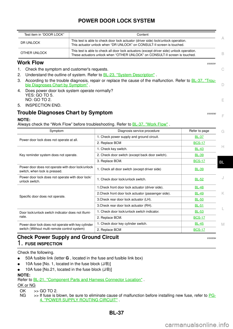
l10A fuse [No. 1, located in the fuse block (J/B)]
l10A fuse [No.21, located in the fuse block (J/B)]
NOTE:
Refer toBL-21, "
Component Parts and Harness Connector Location".
OK or NG
OK >> GO TO 2.
NG >> If fuse is blown, be sure to eliminate cause of malfunction before installing new fuse, refer toPG-
4, "POWER SUPPLY ROUTING CIRCUIT".
DR UNLOCKThis test is able to check door lock actuator (driver side) lock/unlock operation.
This actuator unlock when “DR UNLOCK” on CONSULT-II screen is touched.
OTHER UNLOCKThis test is able to check all door lock actuators (except driver side) unlock operation.
These actuators unlock when “OTHER UNLOCK” on CONSULT-II screen is touched. Test item in “DOOR LOCK” Content
Symptom Diagnosis service procedure Refer to page
Power door lock does not operate at all.1. Check power supply and ground circuit.BL-37
2. Replace BCMBCS-17
Key reminder system does not operate.1. Check key switch.BL-432. Check door switch (except back door switch).BL-39
3. Replace BCM.BCS-17
Power door does not operate with door lock/unlock
switch, when lock is pressed.1. Check all door switch (except driver side)BL-39
Power door lock does not operate with door lock/
unlock switch.1. Check door lock/unlock switch.BL-52
Specific door does not operate.1.Check front door lock actuator (driver side).BL-482.Check front door lock actuator (passenger side).BL-49
3.Check rear door lock actuator (LH).BL-50
3.Check rear door lock actuator (RH).BL-51
Door lock/unlock switch indicator does not illumi-
nate.1. Check door lock/unlock switch indicator.BL-53
2. Replace BCM.BCS-17
Power door lock does not operate with key cylinder
switch (Without multi-remote control system)1. Check door key cylinder switch.BL-45
2. Replace BCMBCS-17
Page 628 of 3171
BL-44
POWER DOOR LOCK SYSTEM
2.CHECK KEY SWITCH SIGNAL CIRCUIT
1. Turn ignition switch OFF.
2. Disconnect BCM connector and key switch connector.
3. Check continuity between BCM harness connector M42 terminal
5 and key switch harness connector M35 terminal 1.
4. Check continuity between BCM harness connector M42 terminal
5 and ground.
OK or NG
OK >> GO TO 3.
NG >> Repair or replace harness between key switch and
BCM.
3.CHECK KEY SWITCH
Check continuity between key switch connector M35 terminals 1 and
2.
OK or NG
OK >> Check the following
l10A fuse [No. 22, located in the fuse block (J/B)]
lHarness for open or short between key switch and
fuse.
NG >> Replace key cylinder assembly.5 – 1 : Continuity should exist.
5 – Ground : Continuity should not exist.
MIIB0884E
Terminal Condition Continuity
12Key is removed from ignition key cylinder. No
Key is inserted in ignition key cylinder. Yes
MIIB0840E
Page 639 of 3171
POWER DOOR LOCK — SUPER LOCK —
BL-55
C
D
E
F
G
H
J
K
L
MA
B
BL
POWER DOOR LOCK — SUPER LOCK —PFP:24814
Component Parts and Harness Connector LocationEIS00DWZ
KING CAB
1. Fuse block (J/B) fuse layout 2. Fuse and fusible link box 3. BCM M42, M43, M44
(View with instrument lower panel LH
removed)
4. Front door lock actuator (Driver side)
D105. Rear door switch NO.2 (LH) D72 6. Front door switch (Driver side) D74
7. Rear door switch NO.1 (LH) D71 8. Door lock/unlock switch M52 9. Key switch M35
MIIB1028E