Page 926 of 3171
DI-16
COMBINATION METERS
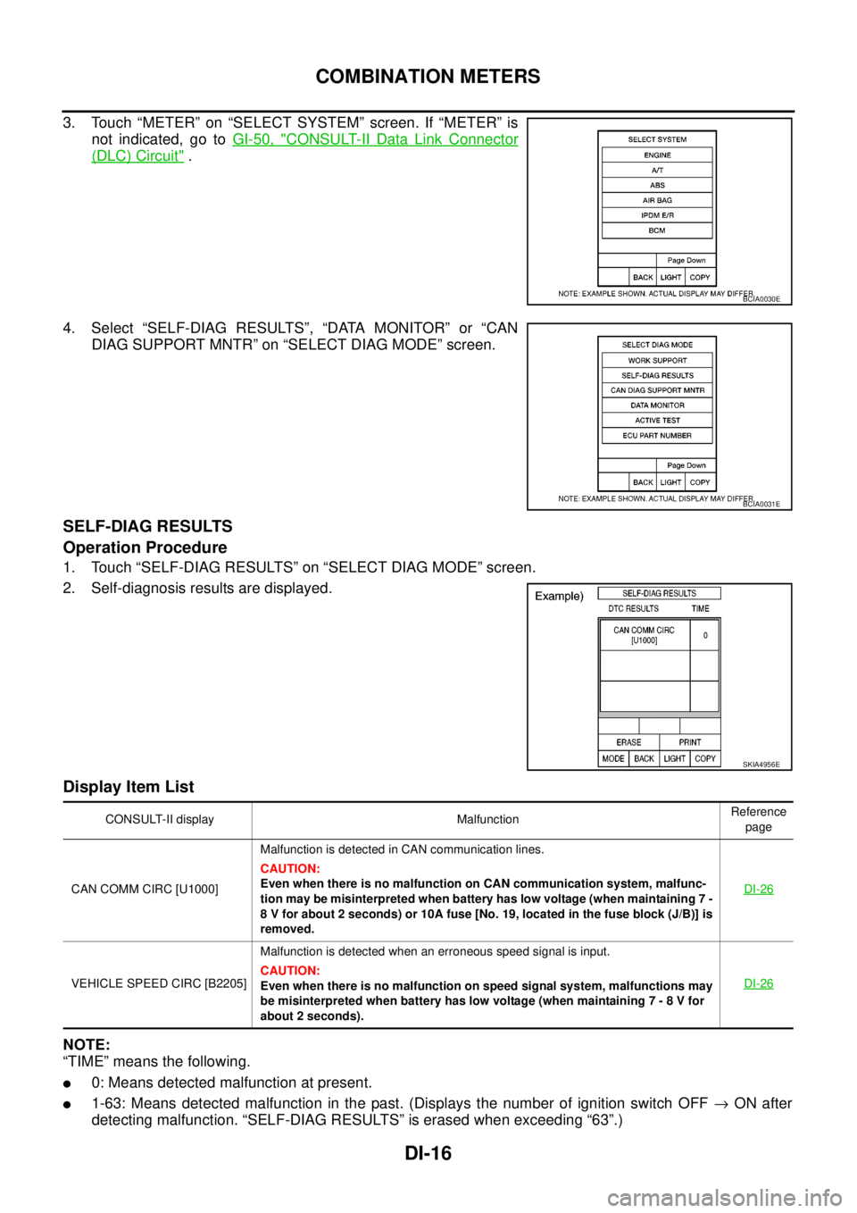
3. Touch “METER” on “SELECT SYSTEM” screen. If “METER” is
not indicated, go toGI-50, "
CONSULT-II Data Link Connector
(DLC) Circuit".
4. Select “SELF-DIAG RESULTS”, “DATA MONITOR” or “CAN
DIAG SUPPORT MNTR” on “SELECT DIAG MODE” screen.
SELF-DIAG RESULTS
Operation Procedure
1. Touch “SELF-DIAG RESULTS” on “SELECT DIAG MODE” screen.
2. Self-diagnosis results are displayed.
Display Item List
NOTE:
“TIME” means the following.
l0: Means detected malfunction at present.
l1-63: Means detected malfunction in the past. (Displays the number of ignition switch OFF®ON after
detecting malfunction. “SELF-DIAG RESULTS” is erased when exceeding “63”.)
BCIA0030E
BCIA0031E
SKIA4956E
CONSULT-II display MalfunctionReference
page
CAN COMM CIRC [U1000]Malfunction is detected in CAN communication lines.
CAUTION:
Even when there is no malfunction on CAN communication system, malfunc-
tion may be misinterpreted when battery has low voltage (when maintaining 7 -
8 V for about 2 seconds) or 10A fuse [No. 19, located in the fuse block (J/B)] is
removed.DI-26
VEHICLE SPEED CIRC [B2205]Malfunction is detected when an erroneous speed signal is input.
CAUTION:
Even when there is no malfunction on speed signal system, malfunctions may
be misinterpreted when battery has low voltage (when maintaining 7 - 8 V for
about 2 seconds).DI-26
Page 929 of 3171
COMBINATION METERS
DI-19
C
D
E
F
G
H
I
J
L
MA
B
DI
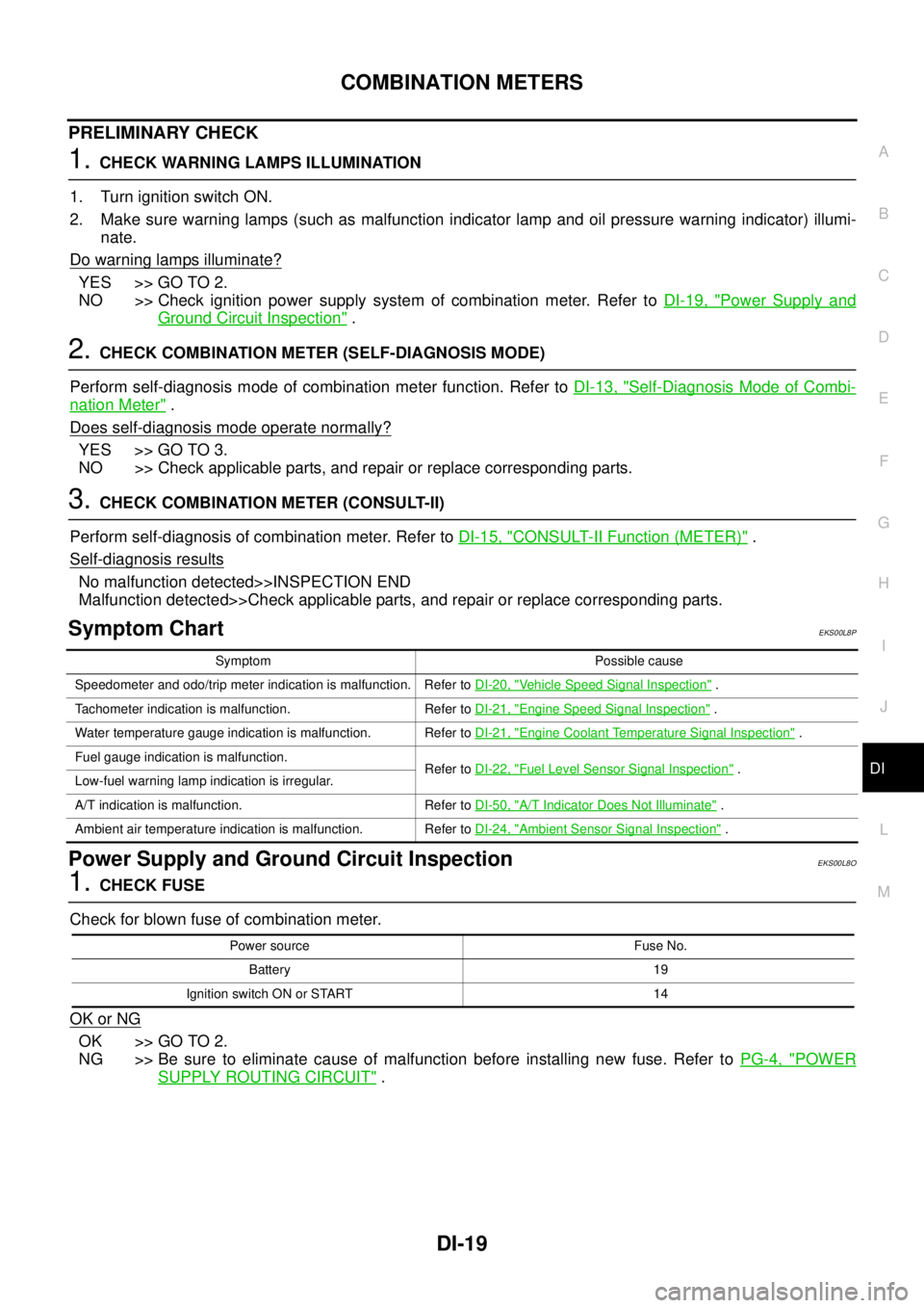
PRELIMINARY CHECK
1.CHECK WARNING LAMPS ILLUMINATION
1. Turn ignition switch ON.
2. Make sure warning lamps (such as malfunction indicator lamp and oil pressure warning indicator) illumi-
nate.
Do warning lamps illuminate?
YES >> GO TO 2.
NO >> Check ignition power supply system of combination meter. Refer toDI-19, "
Power Supply and
Ground Circuit Inspection".
2.CHECK COMBINATION METER (SELF-DIAGNOSIS MODE)
Perform self-diagnosis mode of combination meter function. Refer toDI-13, "
Self-Diagnosis Mode of Combi-
nation Meter".
Does self-diagnosis mode operate normally?
YES >> GO TO 3.
NO >> Check applicable parts, and repair or replace corresponding parts.
3.CHECK COMBINATION METER (CONSULT-II)
Perform self-diagnosis of combination meter. Refer toDI-15, "
CONSULT-II Function (METER)".
Self-diagnosis results
No malfunction detected>>INSPECTION END
Malfunction detected>>Check applicable parts, and repair or replace corresponding parts.
Symptom ChartEKS00L8P
Power Supply and Ground Circuit InspectionEKS00L8O
1.CHECK FUSE
Check for blown fuse of combination meter.
OK or NG
OK >> GO TO 2.
NG >> Be sure to eliminate cause of malfunction before installing new fuse. Refer toPG-4, "
POWER
SUPPLY ROUTING CIRCUIT".
Symptom Possible cause
Speedometer and odo/trip meter indication is malfunction. Refer toDI-20, "
Vehicle Speed Signal Inspection".
Tachometer indication is malfunction. Refer toDI-21, "
Engine Speed Signal Inspection".
Water temperature gauge indication is malfunction. Refer toDI-21, "
Engine Coolant Temperature Signal Inspection".
Fuel gauge indication is malfunction.
Refer toDI-22, "
Fuel Level Sensor Signal Inspection".
Low-fuel warning lamp indication is irregular.
A/T indication is malfunction. Refer toDI-50, "
A/T Indicator Does Not Illuminate".
Ambient air temperature indication is malfunction. Refer toDI-24, "
Ambient Sensor Signal Inspection".
Power source Fuse No.
Battery 19
Ignition switch ON or START 14
Page 930 of 3171
DI-20
COMBINATION METERS
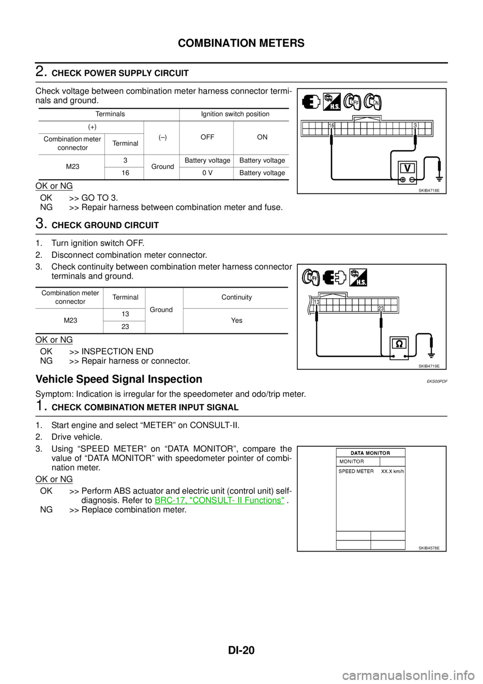
2.CHECK POWER SUPPLY CIRCUIT
Check voltage between combination meter harness connector termi-
nals and ground.
OK or NG
OK >> GO TO 3.
NG >> Repair harness between combination meter and fuse.
3.CHECK GROUND CIRCUIT
1. Turn ignition switch OFF.
2. Disconnect combination meter connector.
3. Check continuity between combination meter harness connector
terminals and ground.
OK or NG
OK >> INSPECTION END
NG >> Repair harness or connector.
Vehicle Speed Signal InspectionEKS00PDF
Symptom: Indication is irregular for the speedometer and odo/trip meter.
1.CHECK COMBINATION METER INPUT SIGNAL
1. Start engine and select “METER” on CONSULT-II.
2. Drive vehicle.
3. Using “SPEED METER” on “DATA MONITOR”, compare the
value of “DATA MONITOR” with speedometer pointer of combi-
nation meter.
OK or NG
OK >> Perform ABS actuator and electric unit (control unit) self-
diagnosis. Refer toBRC-17, "
CONSULT- II Functions".
NG >> Replace combination meter.
Terminals Ignition switch position
(+)
(–) OFF ON
Combination meter
connectorTerminal
M233
GroundBattery voltage Battery voltage
16 0 V Battery voltage
SKIB4718E
Combination meter
connectorTe r m i n a l
GroundContinuity
M2313
Ye s
23
SKIB4719E
SKIB4578E
Page 961 of 3171
WARNING CHIME
DI-51
C
D
E
F
G
H
I
J
L
MA
B
DI
WARNING CHIMEPFP:24814
System DescriptionEKS00L9D
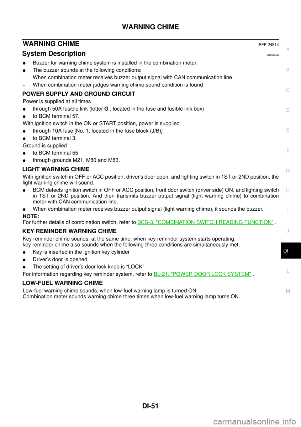
lBuzzer for warning chime system is installed in the combination meter.
lThe buzzer sounds at the following conditions:
–When combination meter receives buzzer output signal with CAN communication line
–When combination meter judges warning chime sound condition is found
POWER SUPPLY AND GROUND CIRCUIT
Power is supplied at all times
lthrough 50A fusible link (letterG, located in the fuse and fusible link box)
lto BCM terminal 57.
With ignition switch in the ON or START position, power is supplied
lthrough 10A fuse [No. 1, located in the fuse block (J/B)]
lto BCM terminal 3.
Ground is supplied
lto BCM terminal 55
lthrough grounds M21, M80 and M83.
LIGHT WARNING CHIME
With ignition switch in OFF or ACC position, driver's door open, and lighting switch in 1ST or 2ND position, the
light warning chime will sound.
lBCM detects ignition switch in OFF or ACC position, front door switch (driver side) ON, and lighting switch
in 1ST or 2ND position. And then transmits buzzer output signal (light warning chime) to combination
meter with CAN communication line.
lWhen combination meter receives buzzer output signal (light warning chime), it sounds the buzzer.
NOTE:
For further details of combination switch, refer toBCS-3, "
COMBINATION SWITCH READING FUNCTION".
KEY REMINDER WARNING CHIME
Key reminder chime sounds, at the same time, when key reminder system starts operating.
key reminder chime also sounds when the following three conditions are simultaneously met.
lKey is inserted in the ignition key cylinder
lDriver¢s door is opened
lThe setting of driver¢s door lock knob is “LOCK”
For information regarding key reminder system, refer toBL-21, "
POWER DOOR LOCK SYSTEM".
LOW-FUEL WARNING CHIME
Low-fuel warning chime sounds, when low-fuel warning lamp is turned ON.
Combination meter sounds warning chime three times when low-fuel warning lamp turns ON.
Page 1053 of 3171
POWER SUPPLY AND GROUND CIRCUIT
EC-73
C
D
E
F
G
H
I
J
K
L
MA
EC
Diagnostic ProcedureEBS01KD8
1.INSPECTION START
Start engine.
Is engine running?
Ye s o r N o
Ye s > > G O T O 7 .
No >> GO TO 2.
2.CHECK ECM POWER SUPPLY CIRCUIT-I
1. Turn ignition switch OFF and then ON.
2. Check voltage between ECM terminals 107, 108 and ground
with CONSULT-II or tester.
OK or NG
OK >> GO TO 4.
NG >> GO TO 3.
3.DETECT MALFUNCTIONING PART
Check the following.
lHarness connectors M91, E101
lFuse block (J/B) connector M88
l10A fuse
lHarness for open or short between ECM and fuse
>> Repair harness or connectors. Voltage: Battery voltage
MBIB0610E
Page 1056 of 3171
EC-76
POWER SUPPLY AND GROUND CIRCUIT
10.CHECK ECM POWER SUPPLY CIRCUIT-V
1. Disconnect ECM harness connector.
2. Disconnect IPDM E/R harness connector E12.
3. Check harness continuity between ECM terminals 105, 113 and IPDM E/R terminal 7.
Refer to Wiring Diagram.
4. Also check harness for short to ground and short to power.
OK or NG
OK >> GO TO 11.
NG >> Repair open circuit or short to ground or short to power in harness or connectors.
11 .CHECK ECM POWER SUPPLY CIRCUIT-VI
Check voltage between ECM terminal 121 and ground with CON-
SULT-II or tester.
OK or NG
OK >> GO TO 13.
NG >> GO TO 12.
12.CHECK 20A FUSE
1. Disconnect 20A fuse from IPDM E/R.
2. Check 20A fuse.
OK or NG
OK >> GO TO 13.
NG >> Replace 20A fuse.Continuity should exist.
Voltage: Battery voltage
MBIB0026E
Page 1175 of 3171
DTC P0504 ASCD BRAKE SWITCH
EC-195
C
D
E
F
G
H
I
J
K
L
MA
EC
4.DETECT MALFUNCTIONING PART
Check the following.
lFuse block (J/B) connector E103
l10A fuse
lHarness for open or short between stop lamp switch and battery
>> Repair open circuit or short to ground or short to power in harness or connectors.
5.CHECK STOP LAMP SWITCH INPUT SIGNAL CIRCUIT FOR OPEN AND SHORT
1. Disconnect ECM harness connector.
2. Check harness continuity between ECM terminal 100 and stop lamp switch terminal 2.
Refer to Wiring Diagram.
3. Also check harness for short to ground and short to power.
OK or NG
OK >> GO TO 6.
NG >> Repair open circuit or short to ground or short to power in harness or connectors.
6.CHECK STOP LAMP SWITCH
Refer toEC-202, "
Component Inspection".
OK or NG
OK >> GO TO 11.
NG >> Replace stop lamp switch.
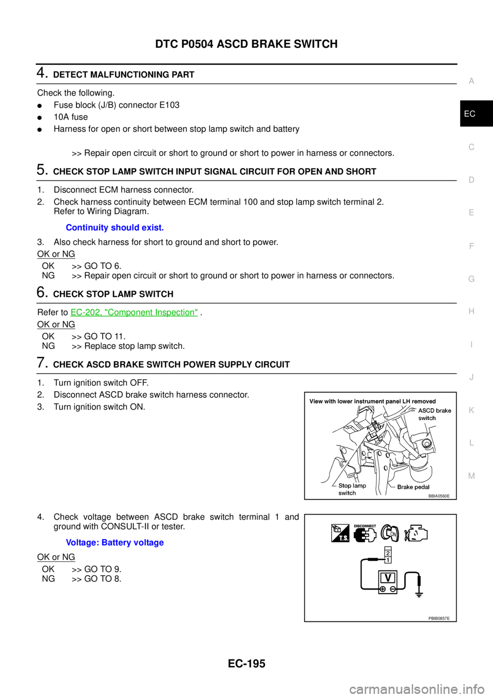
7.CHECK ASCD BRAKE SWITCH POWER SUPPLY CIRCUIT
1. Turn ignition switch OFF.
2. Disconnect ASCD brake switch harness connector.
3. Turn ignition switch ON.
4. Check voltage between ASCD brake switch terminal 1 and
ground with CONSULT-II or tester.
OK or NG
OK >> GO TO 9.
NG >> GO TO 8.Continuity should exist.
BBIA0560E
Voltage: Battery voltage
PBIB0857E
Page 1176 of 3171
EC-196
DTC P0504 ASCD BRAKE SWITCH
8.DETECT MALFUNCTIONING PART
Check the following.
lFuse block (J/B) connector E103
l10A fuse
lHarness for open or short between ASCD brake switch and fuse
>> Repair open circuit or short to ground or short to power in harness or connectors.
9.CHECK ASCD BRAKE SWITCH INPUT SIGNAL CIRCUIT FOR OPEN AND SHORT
1. Disconnect ECM harness connector.
2. Check harness continuity between ECM terminal 101 and ASCD brake switch terminal 2.
Refer to Wiring Diagram.
3. Also check harness for short to ground and short to power.
OK or NG
OK >> GO TO 10.
NG >> Repair open circuit or short to ground or short to power in harness or connectors.
10.CHECK ASCD BRAKE SWITCH
Refer toEC-341, "
Component Inspection"
OK or NG
OK >> GO TO 11.
NG >> Replace ASCD brake switch.
11 .CHECK INTERMITTENT INCIDENT
Refer toEC-70, "
TROUBLE DIAGNOSIS FOR INTERMITTENT INCIDENT".
>>INSPECTION END Continuity should exist.