2005 NISSAN NAVARA window
[x] Cancel search: windowPage 1 of 3171

MODELD40 SERIES
2005 NISSAN EUROPE S.A.S.
All rights reserved. No part of this Electronic Service Manual may be reproduced or stored in a retrieval system, or transmitted in any
form, or by any means, electronic, mechanical, photocopying, recording or otherwise, without the prior written permission of Nissan
Europe S.A.S., Paris, France.
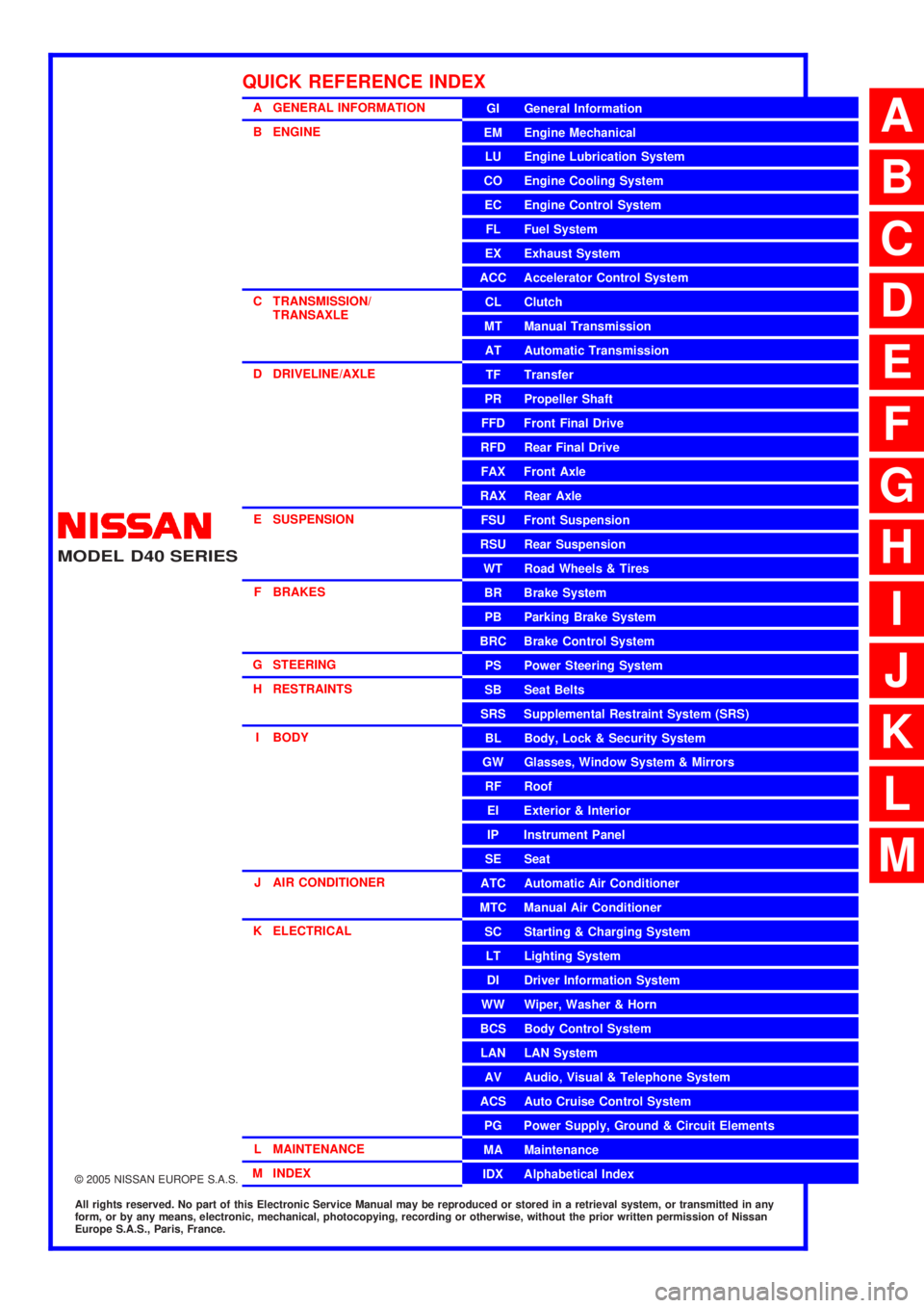
A GENERAL INFORMATION
B ENGINE
C TRANSMISSION/TRANSAXLE
D DRIVELINE/AXLE
E SUSPENSION F BRAKES
G STEERING H RESTRAINTS
I BODY
J AIR CONDITIONER
K ELECTRICAL
L MAINTENANCE
M INDEXGI General Information
EM Engine Mechanical
LU Engine Lubrication System
CO Engine Cooling System
EC Engine Control System
FL Fuel System
EX Exhaust System
ACC Accelerator Control System
CL Clutch
MTManualTransmission
AT Automatic Transmission
TF Transfer
PR Propeller Shaft
FFD Front Final Drive
RFD Rear Final Drive
FAX Front Axle
RAX Rear Axle
FSU Front Suspension
RSU Rear Suspension
WT Road Wheels & Tires
BR Brake System
PB Parking Brake System
BRC Brake Control System
PS Power Steering System
SB Seat Belts
SRS Supplemental Restraint System (SRS)
BL Body, Lock & Security System
GW Glasses, Window System & Mirrors
RF Roof
EI Exterior & Interior
IP Instrument Panel
SE Seat
ATC Automatic Air Conditioner
MTC Manual Air Conditioner
SC Starting & Charging System
LT Lighting System
DI Driver Information System
WW Wiper, Washer & Horn
BCS Body Control System
LAN LAN System
AV Audio, Visual & Telephone System
ACS Auto Cruise Control System
PG Power Supply, Ground & Circuit Elements
MA Maintenance
IDX Alphabetical Index
QUICK REFERENCE INDEX
A
B
C
D
E
F
G
H
I
J
K
L
M
Page 335 of 3171

ATC-1
AUTOMATIC AIR CONDITIONER
J AIR CONDITIONER
CONTENTS
C
D
E
F
G
H
I
K
L
M
SECTIONAT C
A
B
AT C
AUTOMATIC AIR CONDITIONER
PRECAUTIONS .......................................................... 4
Precautions for Supplemental Restraint System
(SRS)“AIRBAG”and“SEATBELTPRE-TEN-
SIONER” .................................................................. 4
Precautions for Working with HFC-134a (R-134a)..... 4
Contaminated Refrigerant ........................................ 4
General Refrigerant Precautions .............................. 5
Precautions for Refrigerant Connection ................... 5
ABOUT ONE-TOUCH JOINT ................................ 5
FEATURES OF NEW TYPE REFRIGERANT
CONNECTION ...................................................... 7
O-RING AND REFRIGERANT CONNECTION..... 9
Precautions for Servicing Compressor ................... 12
Precautions for Service Equipment ........................ 12
RECOVERY/RECYCLING EQUIPMENT ............ 12
ELECTRONIC LEAK DETECTOR ...................... 12
VACUUM PUMP ................................................. 13
MANIFOLD GAUGE SET .................................... 13
SERVICE HOSES ............................................... 13
SERVICE COUPLERS ........................................ 14
REFRIGERANT WEIGHT SCALE ...................... 14
CALIBRATING ACR4 WEIGHT SCALE .............. 14
CHARGING CYLINDER ...................................... 14
Precautions for Leak Detection Dye ....................... 14
IDENTIFICATION ................................................ 15
IDENTIFICATION LABEL FOR VEHICLE ........... 15
Wiring Diagrams and Trouble Diagnosis ................ 15
PREPARATION ......................................................... 16
Special Service Tools ............................................. 16
HFC-134a (R-134a) Service Tools and Equipment... 16
Commercial Service Tools ...................................... 19
REFRIGERATION SYSTEM ..................................... 20
Refrigerant Cycle ................................................... 20
REFRIGERANT FLOW ....................................... 20
FREEZE PROTECTION ..................................... 20
Refrigerant System Protection ............................... 20
REFRIGERANT PRESSURE SENSOR ............. 20
PRESSURE RELIEF VALVE ............................... 21
Components ........................................................... 22
REFRIGERATION SYSTEM ............................... 22LUBRICANT .............................................................. 24
Maintenance of Lubricant Quantity in Compressor... 24
LUBRICANT ........................................................ 24
CHECKING AND ADJUSTING ............................ 24
AIR CONDITIONER CONTROL ............................... 26
Description .............................................................. 26
Operation ................................................................ 26
AIR MIX DOORS CONTROL .............................. 26
BLOWER SPEED CONTROL ............................. 26
INTAKE DOOR CONTROL ................................. 26
MODE DOOR CONTROL ................................... 26
DEFROSTER DOOR CONTROL ........................ 26
MAGNET CLUTCH CONTROL ........................... 27
SELF-DIAGNOSTIC SYSTEM ............................ 27
Description of Control System ................................ 28
Control Operation ................................................... 28
DISPLAY SCREEN .............................................. 29
AUTO SWITCH ................................................... 29
TEMPERATURE CONTROL DIAL (TEMPERA-
TURE CONTROL) (DRIVER SIDE) ..................... 29
TEMPERATURE CONTROL DIAL (TEMPERA-
TURE CONTROL) (PASSENGER SIDE) ............ 29
TEMPERATURE CONTROL DIAL (TEMPERA-
TURE AND MODE CONTROL) (REAR) ............. 29
RECIRCULATION (REC) SWITCH ..................... 29
DEFROSTER (DEF) SWITCH ............................. 29
REAR WINDOW DEFOGGER SWITCH ............. 29
OFF SWITCH ...................................................... 29
A/C SWITCH ....................................................... 29
MODE SWITCH (FRONT) ................................... 29
FRONT BLOWER CONTROL DIAL .................... 29
MODE SWITCH (REAR) ..................................... 29
Discharge Air Flow ................................................. 30
FRONT ................................................................ 30
System Description ................................................. 31
SWITCHES AND THEIR CONTROL FUNCTION... 31
CAN Communication System Description .............. 32
TROUBLE DIAGNOSIS ............................................ 33
CONSULT-II Function (BCM) ................................. 33
CONSULT-II BASIC OPERATION ....................... 33
Page 363 of 3171

AIR CONDITIONER CONTROL
ATC-29
C
D
E
F
G
H
I
K
L
MA
B
AT C
DISPLAY SCREEN
Displays the operational status of the system.
AUTO SWITCH
lThe compressor, intake door, air mix doors, outlet doors and blower speed are automatically controlled so
that the in-vehicle temperature will reach, and be maintained at the set temperature selected by the oper-
ator.
lWhen pressing AUTO switch, air inlet, air outlet, blower speed, and discharge air temperature are auto-
matically controlled.
TEMPERATURE CONTROL DIAL (TEMPERATURE CONTROL) (DRIVER SIDE)
Increases or decreases the set temperature.
TEMPERATURE CONTROL DIAL (TEMPERATURE CONTROL) (PASSENGER SIDE)
Increases or decreases the set temperature.
TEMPERATURE CONTROL DIAL (TEMPERATURE AND MODE CONTROL) (REAR)
Increases or decreases the set temperature. The mode also changes from foot at full hot setting, to foot/vent
mid-range (warm) setting, and then to vent on full cold setting.
RECIRCULATION (REC) SWITCH
lWhen REC switch is ON, REC switch indicator turns ON, and air inlet is set to REC.
lWhen REC switch is turned OFF, or when compressor is turned from ON to OFF, REC switch is automati-
cally turned OFF. REC mode can be re-entered by pressing REC switch again.
lREC switch is not operated when DEF switch is turned ON, or at the D/F position.
DEFROSTER (DEF) SWITCH
Positions the air outlet doors to the defrost position. Also positions the intake doors to the outside air position.
REAR WINDOW DEFOGGER SWITCH
When switch is ON, rear window is defogged.
OFF SWITCH
The compressor and blower are OFF, the intake doors are set to the outside air position, and the air outlet
doors are set to the foot (75% foot and 25% defrost) position.
A/C SWITCH
The compressor is ON or OFF.
(Pressing the A/C switch when the AUTO switch is ON will turn off the A/C switch and compressor.)
MODE SWITCH (FRONT)
Controls the air discharge outlets.
FRONT BLOWER CONTROL DIAL
Manually control the blower speed. Seven speeds are available for manual control (as shown on the display
screen).
MODE SWITCH (REAR)
Controls the air/temperature at discharge outlets.
Page 390 of 3171

ATC-56
TROUBLE DIAGNOSIS
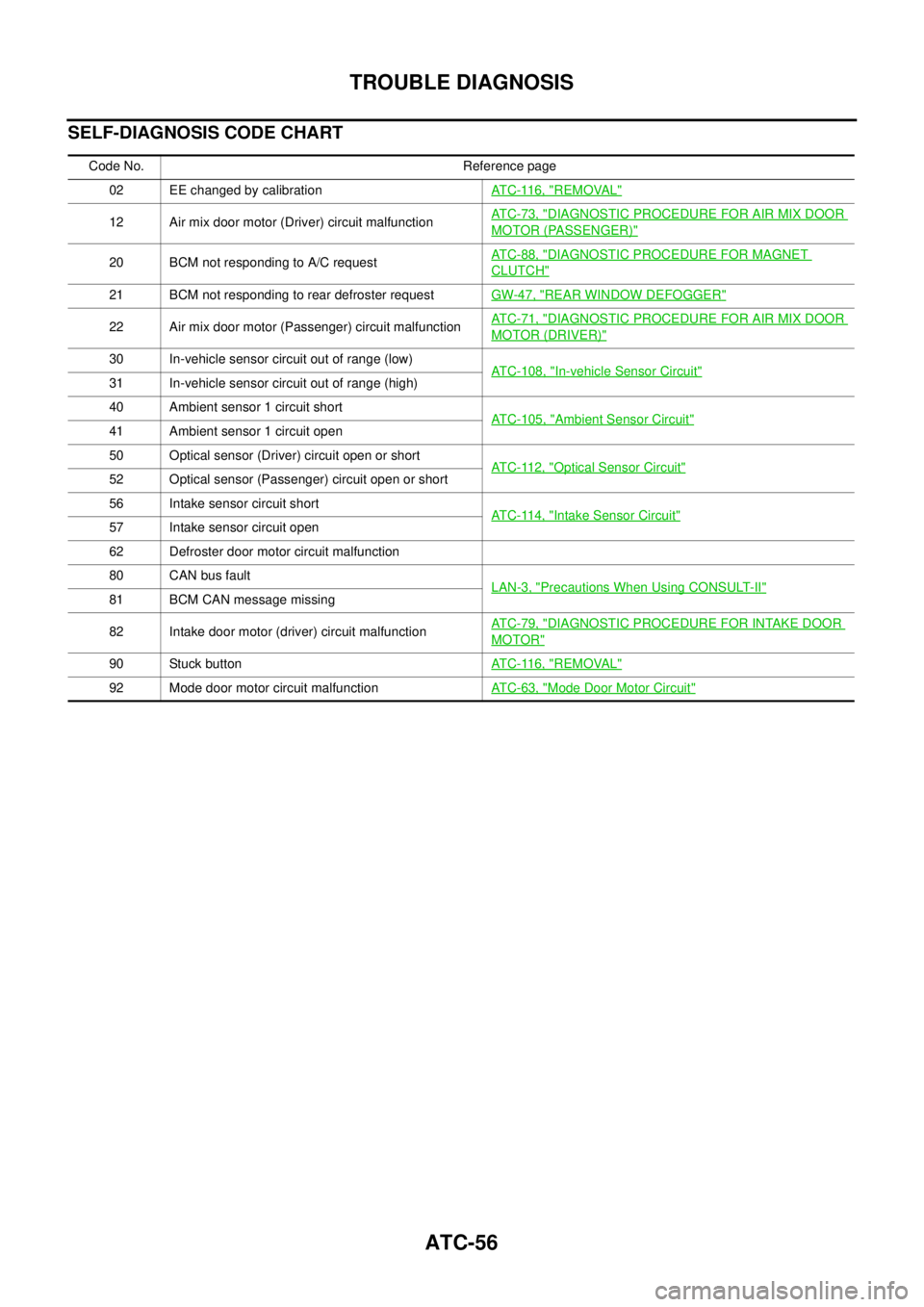
SELF-DIAGNOSIS CODE CHART
Code No. Reference page
02 EE changed by calibrationATC-116, "
REMOVAL"
12 Air mix door motor (Driver) circuit malfunctionATC-73, "DIAGNOSTIC PROCEDURE FOR AIR MIX DOOR
MOTOR (PASSENGER)"
20 BCM not responding to A/C requestATC-88, "DIAGNOSTIC PROCEDURE FOR MAGNET
CLUTCH"
21 BCM not responding to rear defroster requestGW-47, "REAR WINDOW DEFOGGER"
22 Air mix door motor (Passenger) circuit malfunctionATC-71, "DIAGNOSTIC PROCEDURE FOR AIR MIX DOOR
MOTOR (DRIVER)"
30 In-vehicle sensor circuit out of range (low)
ATC-108, "In-vehicle Sensor Circuit"31 In-vehicle sensor circuit out of range (high)
40 Ambient sensor 1 circuit short
ATC-105, "
Ambient Sensor Circuit"41 Ambient sensor 1 circuit open
50 Optical sensor (Driver) circuit open or short
ATC-112, "
Optical Sensor Circuit"52 Optical sensor (Passenger) circuit open or short
56 Intake sensor circuit short
ATC-114, "
Intake Sensor Circuit"57 Intake sensor circuit open
62 Defroster door motor circuit malfunction
80 CAN bus fault
LAN-3, "
Precautions When Using CONSULT-II"81 BCM CAN message missing
82 Intake door motor (driver) circuit malfunctionATC-79, "
DIAGNOSTIC PROCEDURE FOR INTAKE DOOR
MOTOR"
90 Stuck buttonATC-116, "REMOVAL"
92 Mode door motor circuit malfunctionATC-63, "Mode Door Motor Circuit"
Page 430 of 3171

ATC-96
TROUBLE DIAGNOSIS
PERFORMANCE CHART
Test Condition
Testing must be performed as follows:
Test Reading
Recirculating-to-discharge Air Temperature Table
Ambient Air Temperature-to-operating Pressure Table
Vehicle location Indoors or in the shade (in a well-ventilated place)
Doors Closed
Door window Open
Hood Open
TEMP. Max. COLD
Mode switch
(Ventilation) set
Recirculation (REC) switch
(Recirculation) set
Blower speedMax. speed set
Engine speed Idle speed
Operate the air conditioning system for 10 minutes before taking measurements.
Inside air (Recirculating air) at blower assembly inlet
Discharge air temperature at center ventilator
°C(°F) Relative humidity
%Air temperature
°C(°F)
40 - 6020 (68) 9.6 - 12.0 (49 - 54)
25 (77) 13.6 - 16.5 (56 - 62)
30 (86) 18.0 - 21.4 (64 - 71)
35 (95) 22.8 - 26.7 (73 - 80)
60 - 8020 (68) 12.0 - 14.3 (54 - 58)
25 (77) 16.5 - 19.3 (62 - 67)
30 (86) 21.4 - 24.8 (71 - 77)
35 (95) 26.7 - 30.5 (80 - 87)
Ambient air
High-pressure (Discharge side)
kPa (kg/cm
2, psi)Low-pressure (Suction side)
kPa (kg/cm2, psi) Relative humidity
%Air temperature
°C(°F)
40 - 6020 (68)1,090 - 1,210
(11.11 - 12.33, 158.0 - 175.4)220 - 240
(2.24 - 2.45, 31.9 - 34.8)
25 (77)1,370 - 1,520
(13.97 - 15.49, 198.6 - 220.3)280 - 310
(2.85 - 3.16, 40.6 - 44.9)
30 (86)1,610 - 1,790
(16.41 - 18.25, 233.4 - 259.5)330 - 370
(3.36 - 3.77, 47.8 - 53.6)
35 (95)1,940 - 2,150
(19.78 - 21.92, 281.2 - 311.7)390 - 430
(3.98 - 4.38, 56.5 - 62.3)
60 - 8020 (68)1,210 - 1,330
(12.33 - 13.56, 175.4 - 192.8)240 - 260
(2.45 - 2.65, 34.8 - 37.7)
25 (77)1,520 - 1,670
(15.49 - 17.02, 220.3 - 242.1)310 - 340
(3.16 - 3.47, 44.9 - 49.3)
30 (86)1,790 - 1,970
(18.25 - 20.08, 259.5 - 285.6)370 - 410
(3.77 - 4.18, 53.6 - 59.4)
35 (95)2,150 - 2,370
(21.92 - 24.16, 311.7 - 343.5)430 - 470
(4.38 - 4.79, 62.3 - 68.1)
Page 484 of 3171

ATC-150
REFRIGERANT LINES
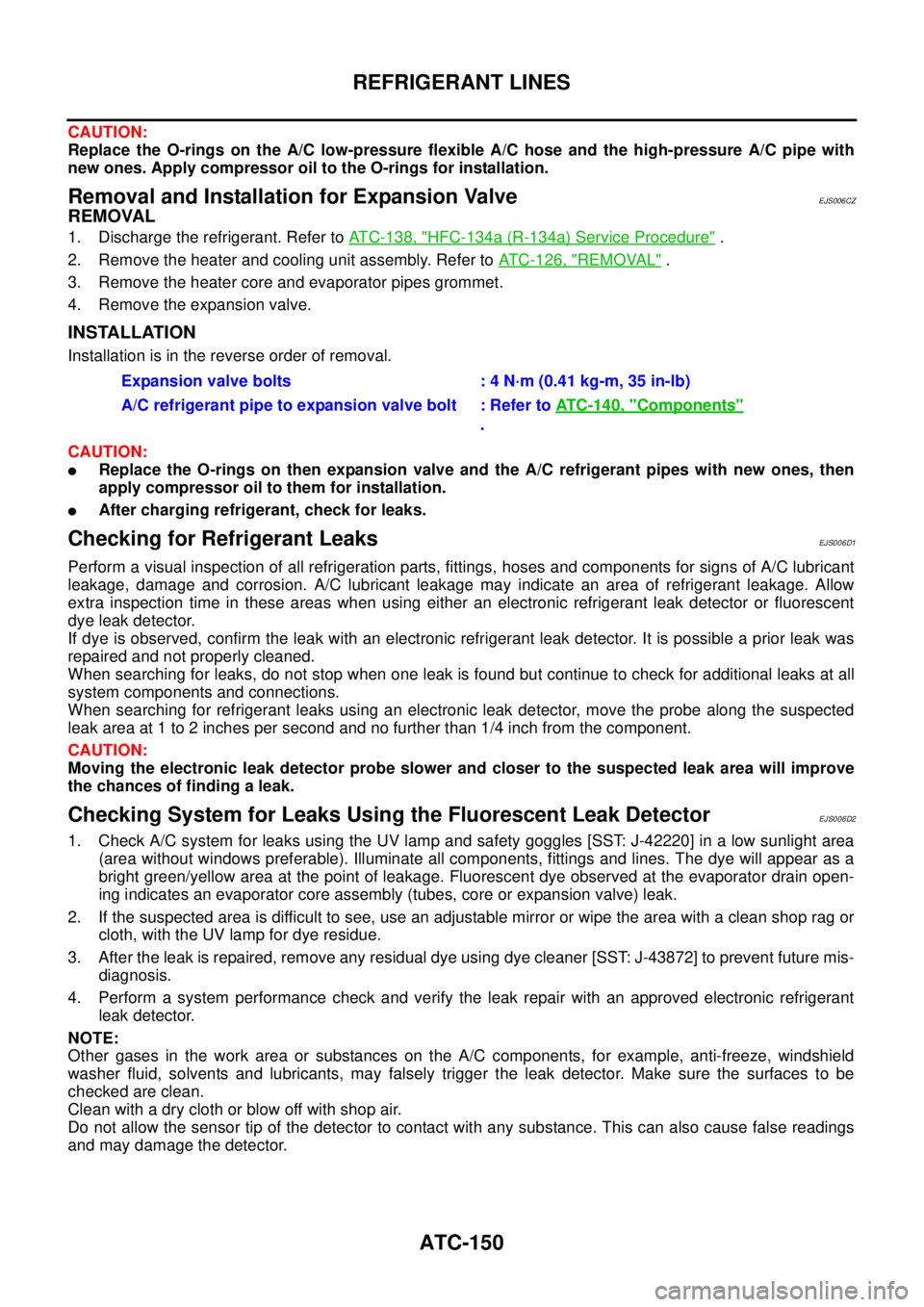
CAUTION:
Replace the O-rings on the A/C low-pressure flexible A/C hose and the high-pressure A/C pipe with
new ones. Apply compressor oil to the O-rings for installation.
Removal and Installation for Expansion ValveEJS006CZ
REMOVAL
1. Discharge the refrigerant. Refer toATC-138, "HFC-134a (R-134a) Service Procedure".
2. Remove the heater and cooling unit assembly. Refer toATC-126, "
REMOVAL".
3. Remove the heater core and evaporator pipes grommet.
4. Remove the expansion valve.
INSTALLATION
Installation is in the reverse order of removal.
CAUTION:
lReplace the O-rings on then expansion valve and the A/C refrigerant pipes with new ones, then
apply compressor oil to them for installation.
lAfter charging refrigerant, check for leaks.
Checking for Refrigerant LeaksEJS006D1
Perform a visual inspection of all refrigeration parts, fittings, hoses and components for signs of A/C lubricant
leakage, damage and corrosion. A/C lubricant leakage may indicate an area of refrigerant leakage. Allow
extra inspection time in these areas when using either an electronic refrigerant leak detector or fluorescent
dye leak detector.
If dye is observed, confirm the leak with an electronic refrigerant leak detector. It is possible a prior leak was
repaired and not properly cleaned.
When searching for leaks, do not stop when one leak is found but continue to check for additional leaks at all
system components and connections.
When searching for refrigerant leaks using an electronic leak detector, move the probe along the suspected
leak area at 1 to 2 inches per second and no further than 1/4 inch from the component.
CAUTION:
Moving the electronic leak detector probe slower and closer to the suspected leak area will improve
the chances of finding a leak.
Checking System for Leaks Using the Fluorescent Leak DetectorEJS006D2
1. Check A/C system for leaks using the UV lamp and safety goggles [SST: J-42220] in a low sunlight area
(area without windows preferable). Illuminate all components, fittings and lines. The dye will appear as a
bright green/yellow area at the point of leakage. Fluorescent dye observed at the evaporator drain open-
ing indicates an evaporator core assembly (tubes, core or expansion valve) leak.
2. If the suspected area is difficult to see, use an adjustable mirror or wipe the area with a clean shop rag or
cloth, with the UV lamp for dye residue.
3. After the leak is repaired, remove any residual dye using dye cleaner [SST: J-43872] to prevent future mis-
diagnosis.
4. Perform a system performance check and verify the leak repair with an approved electronic refrigerant
leak detector.
NOTE:
Other gases in the work area or substances on the A/C components, for example, anti-freeze, windshield
washer fluid, solvents and lubricants, may falsely trigger the leak detector. Make sure the surfaces to be
checked are clean.
Cleanwithadryclothorblowoffwithshopair.
Do not allow the sensor tip of the detector to contact with any substance. This can also cause false readings
and may damage the detector.Expansion valve bolts : 4 N·m (0.41 kg-m, 35 in-lb)
A/C refrigerant pipe to expansion valve bolt : Refer toATC-140, "
Components"
.
Page 549 of 3171

TROUBLE DIAGNOSIS
AV-61
C
D
E
F
G
H
I
J
L
MA
B
AV
TROUBLE DIAGNOSISPFP:00004
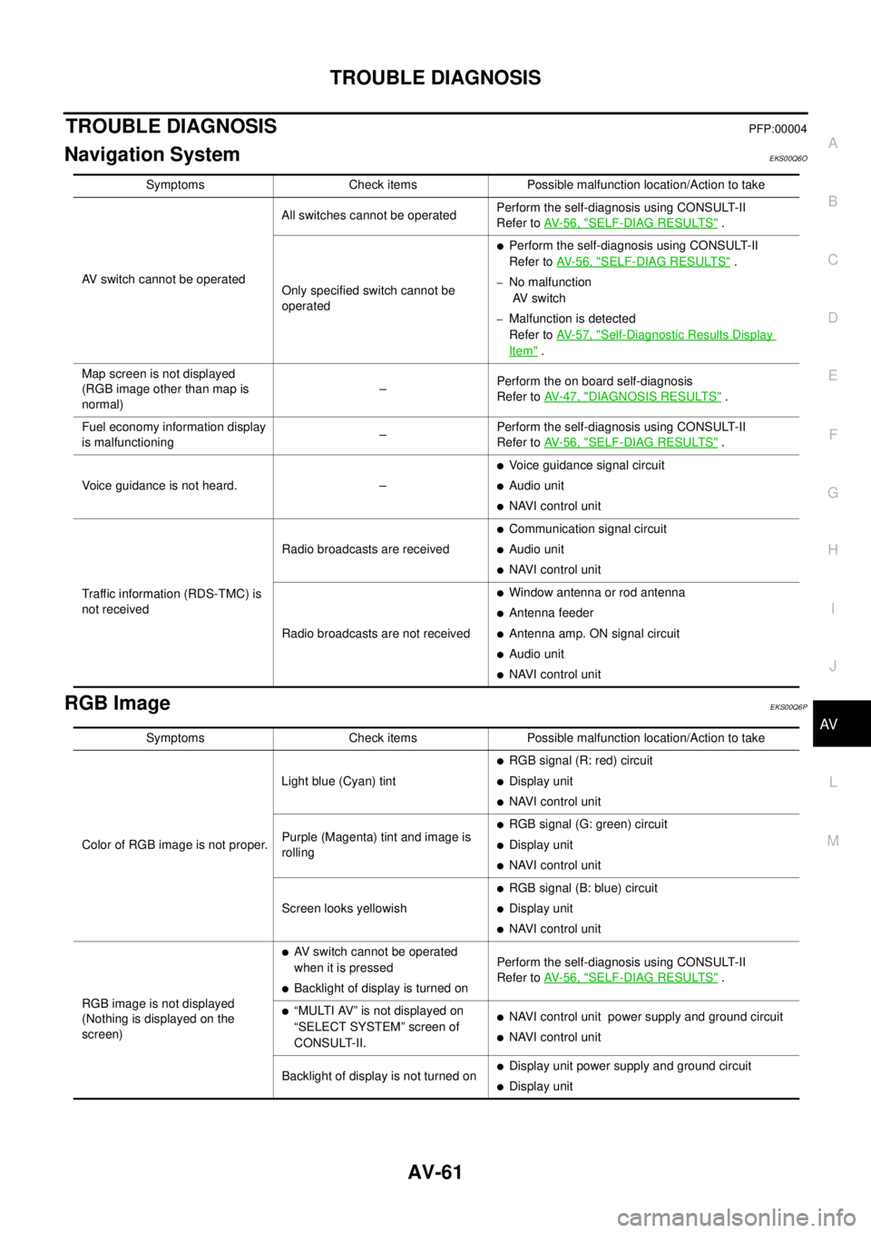
Navigation SystemEKS00Q6O
RGB ImageEKS00Q6P
Symptoms Check items Possible malfunction location/Action to take
AV switch cannot be operatedAll switches cannot be operatedPerform the self-diagnosis using CONSULT-II
Refer toAV-56, "
SELF-DIAG RESULTS".
Only specified switch cannot be
operated
lPerform the self-diagnosis using CONSULT-II
Refer toAV-56, "
SELF-DIAG RESULTS".
–No malfunction
AV switch
–Malfunction is detected
Refer toAV-57, "
Self-Diagnostic Results Display
Item".
Map screen is not displayed
(RGB image other than map is
normal)–Perform the on board self-diagnosis
Refer toAV-47, "
DIAGNOSIS RESULTS".
Fuel economy information display
is malfunctioning–Perform the self-diagnosis using CONSULT-II
Refer toAV-56, "
SELF-DIAG RESULTS".
Voice guidance is not heard. –
lVoice guidance signal circuit
lAudio unit
lNAVI control unit
Traffic information (RDS-TMC) is
not receivedRadio broadcasts are received
lCommunication signal circuit
lAudio unit
lNAVI control unit
Radio broadcasts are not received
lWindow antenna or rod antenna
lAntenna feeder
lAntenna amp. ON signal circuit
lAudio unit
lNAVI control unit
Symptoms Check items Possible malfunction location/Action to take
Color of RGB image is not proper.Light blue (Cyan) tint
lRGB signal (R: red) circuit
lDisplay unit
lNAVI control unit
Purple (Magenta) tint and image is
rolling
lRGB signal (G: green) circuit
lDisplay unit
lNAVI control unit
Screen looks yellowish
lRGB signal (B: blue) circuit
lDisplay unit
lNAVI control unit
RGB image is not displayed
(Nothing is displayed on the
screen)
lAV switch cannot be operated
when it is pressed
lBacklight of display is turned onPerform the self-diagnosis using CONSULT-II
Refer toAV-56, "SELF-DIAG RESULTS".
l“MULTI AV” is not displayed on
“SELECT SYSTEM” screen of
CONSULT-II.lNAVI control unit power supply and ground circuit
lNAVI control unit
Backlight of display is not turned on
lDisplay unit power supply and ground circuit
lDisplay unit
Page 555 of 3171

TROUBLE DIAGNOSIS
AV-67
C
D
E
F
G
H
I
J
L
MA
B
AV
VOICE GUIDANCE
VOICE RECOGNITION
An indirect route is suggested.If there are restrictions (such as one way streets)
on roads close to the starting point or destination,
the system may suggest an indirect route.Adjust the location of the starting point or
destination.
The system may suggest an indirect route because
route calculation does not take into consideration
some areas such as narrow streets (gray roads).Reset the destination to a main or ordinary
road, and recalculate the route.
The landmark information does not
correspond to the actual informa-
tion.This may caused by insufficient or incorrect data on
the DVD-ROM.This is not a malfunction.
The suggested route does not
exactly connect to the starting
point, waypoints, or destination.There is no data for route calculation closer to
these locations.Set the starting point, waypoints and desti-
nation on main road, and perform route cal-
culation. Symptom Possible cause Possible solution
Symptom Possible cause Possible solution
The voice guidance is not avail-
able.Voice guidance is only available at certain intersec-
tions. In some cases, voice guidance is not avail-
able even when the vehicle should make a turn.This is not a malfunction.
The vehicle has deviated from the suggested
route.Go back to the suggested route or request
route calculation again.
Voice guidance is set to off. Turn on the voice guidance.
Route guidance is set to off. Turn on the voice guidance.
The guidance content does not
correspond to the actual condition.The content of the voice guidance may vary,
depending on the types of intersections at which
turns are made.Follow all traffic rules and regulations.
Symptom Possible cause Possible solution
The system does not recognize
the command.
The system recognizes the com-
mand incorrectly.The interior of the vehicle is too noisy.Close the windows or have other occu-
pants be quiet.
The volume of the voice is too low. Speak louder.
Pronounceation is unclear. Speak clearly.
Voice recognition mode is not yet ready to speak.Push the release “PPT” on the steering
switch, and speak a command after the
tone sounds.
5 seconds or more have passed after pushed and
released “PTT” on the steering switch.Make sure to speak a command within 5
seconds after push and release “PTT” on
the steering switch.
Only a limited range of voice commands is usable
for each screen.Use a correct voice command appropriate
for the current screen.