Page 1388 of 3171
EM-6
PREPARATION
PREPARATION
PFP:00002
Special Service ToolsEBS01E5O
Tool number
Tool nameDescription
KV10115600
Valve oil seal driftInstalling valve oil seal
UsesideA.
Side A
a: 20 (0.79) dia.
b: 13 (0.51) dia.
c: 10.3 (0.406) dia.
d: 8 (0.31) dia.
e: 10.7 (0.421)
f: 5 (0.20)
Unit: mm (in)
KV10107902
Valve oil seal puller
1. KV10116100
Valve oil seal puller adapterRemoving valve oil seal
KV11103000
Pulley pullerRemoving crankshaft pulley
ED19600610
Compression gauge adapterChecking compression pressure
KV101056S0
Ring gear stopper
1. KV10105630
Adapter
2. KV10105610
PlatePreventing crankshaft from rotating
a: 3 (0.12)
b: 6.4 (0.252)
c: 2.8 (0.110)
d: 6.6 (0.260)
e: 107 (4.21)
f: 14 (0.55)
g: 20 (0.79)
h: 14 (0.55) dia.
Unit: mm (in)
KV101151S0
Lifter stopper set
1. KV10115110
Camshaft pliers
2. KV10115120
Lifter stopperChanging adjusting shim
NT603
S-NT605
NT676
ZZA1188D
NT617
NT041
Page 1474 of 3171
EM-92
CYLINDER HEAD
CYLINDER HEAD
PFP:11041
On-Vehicle ServiceEBS01E6A
CHECKING COMPRESSION PRESSURE
1. Warm up engine thoroughly. Then, stop it.
2. Using CONSULT-II, make sure no error codes are indicated for self-diagnosis items. Refer toEC-38,
"Basic Inspection".
lDo not disconnect CONSULT-II until the end of this operation; it will be used to check engine rpm and
for error detection at the end of this operation.
3. Disconnect the battery cable from the negative terminal.
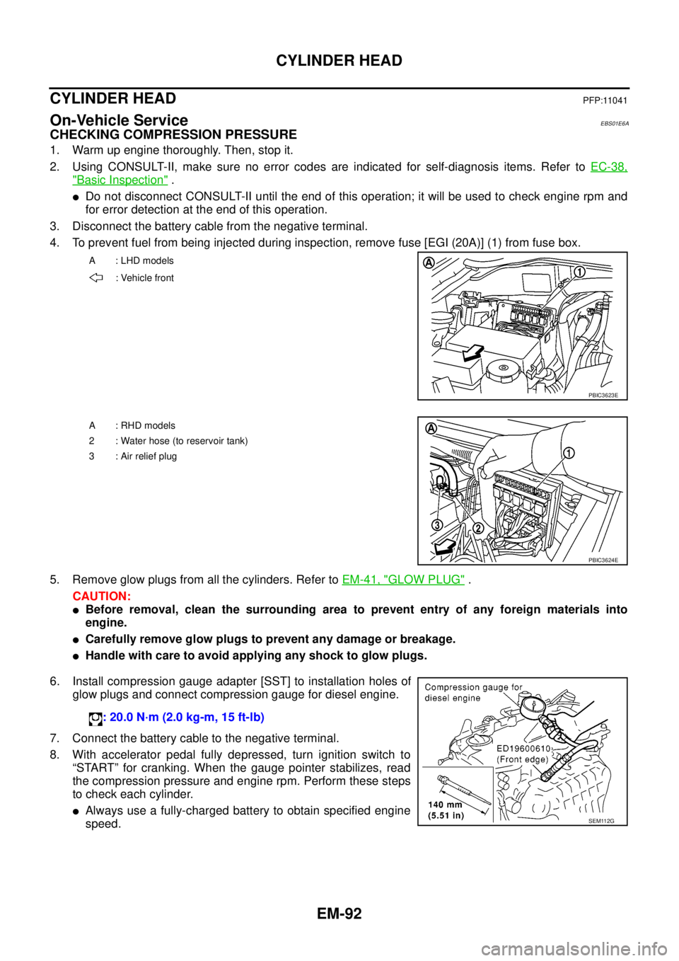
4. To prevent fuel from being injected during inspection, remove fuse [EGI (20A)] (1) from fuse box.
5. Remove glow plugs from all the cylinders. Refer toEM-41, "
GLOW PLUG".
CAUTION:
lBefore removal, clean the surrounding area to prevent entry of any foreign materials into
engine.
lCarefully remove glow plugs to prevent any damage or breakage.
lHandle with care to avoid applying any shock to glow plugs.
6. Install compression gauge adapter [SST] to installation holes of
glow plugs and connect compression gauge for diesel engine.
7. Connect the battery cable to the negative terminal.
8. With accelerator pedal fully depressed, turn ignition switch to
“START” for cranking. When the gauge pointer stabilizes, read
the compression pressure and engine rpm. Perform these steps
to check each cylinder.
lAlways use a fully-charged battery to obtain specified engine
speed.
A : LHD models
: Vehicle front
PBIC3623E
A : RHD models
2 : Water hose (to reservoir tank)
3:Airreliefplug
PBIC3624E
: 20.0 N·m (2.0 kg-m, 15 ft-lb)
SEM112G
Page 1475 of 3171
CYLINDER HEAD
EM-93
C
D
E
F
G
H
I
J
K
L
MA
EM
Compression pressure
Unit: kPa (bar, kg/cm2, psi)/rpm
lWhen engine rpm is out of the specified range, check the specific gravity of battery liquid. Measure
again under corrected conditions.
lIf engine rpm exceeds the limit, check valve clearance and combustion chamber components (valves,
valve seats, cylinder head gaskets, piston rings, pistons, cylinder bores, cylinder block upper and lower
surfaces) and measure again.
lIf compression pressure is low in some cylinders, apply engine oil from glow plug installation hole. Then
check pressure again.
–If compression pressure becomes normal after applying engine oil, piston ring may be worn or dam-
aged. Check piston ring for malfunction. If any, replace piston ring.
–If compression pressure is still low after applying engine oil, valve may be malfunctioning. Check valve
for malfunction. If contact malfunction is found, replace valve or valve seat.
lIf compression pressure in adjacent two cylinders is low after applying engine oil, pressure may be
leaking from gasket. In this case, replace cylinder head gasket.
9. Complete this operation as follows:
a. Turn the ignition switch to “OFF”.
b. Disconnect the battery cable from the negative terminal.
c. Install glow plug and install all the parts removed in step 4.
d. Install fuse [EGI (20A)].
e. Connect the battery cable to the negative terminal.
f. Using CONSULT-II make sure no DTC is indicated for items of self-diagnosis.
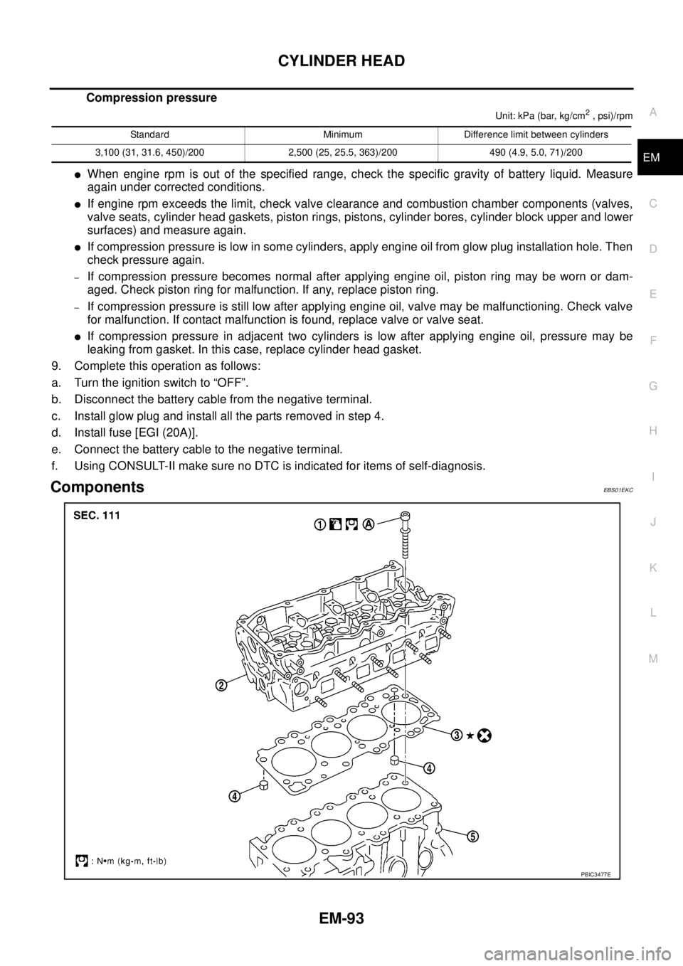
ComponentsEBS01EKC
Standard Minimum Difference limit between cylinders
3,100 (31, 31.6, 450)/200 2,500 (25, 25.5, 363)/200 490 (4.9, 5.0, 71)/200
PBIC3477E
Page 1517 of 3171
SERVICE DATA AND SPECIFICATIONS (SDS)
EM-135
C
D
E
F
G
H
I
J
K
L
MA
EM
SERVICE DATA AND SPECIFICATIONS (SDS)PFP:00030
Standard and LimitEBS01E6H
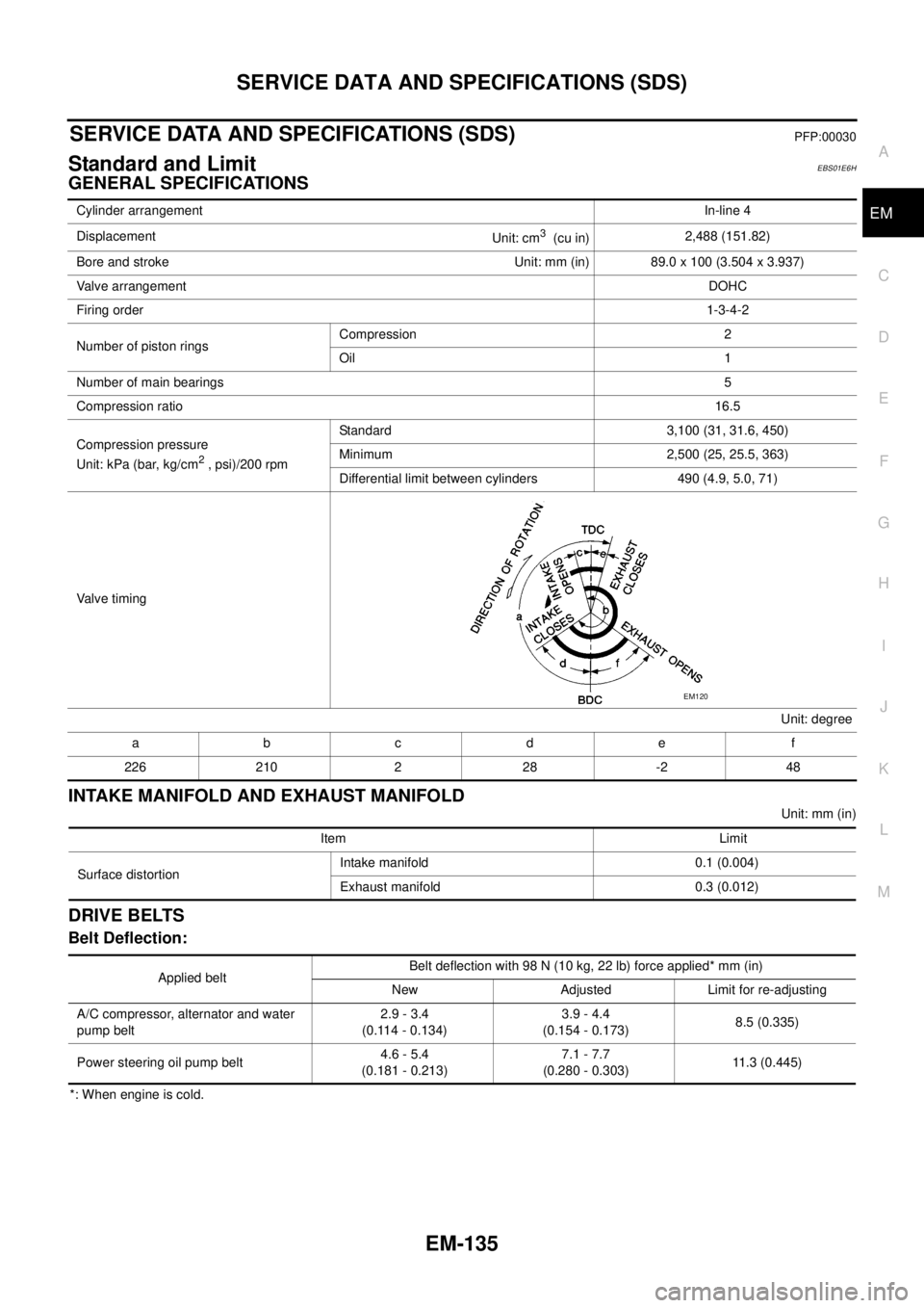
GENERAL SPECIFICATIONS
INTAKE MANIFOLD AND EXHAUST MANIFOLD
Unit: mm (in)
DRIVE BELTS
Belt Deflection:
*: When engine is cold.Cylinder arrangementIn-line 4
Displacement
Unit: cm
3(cu in)2,488 (151.82)
Bore and stroke Unit: mm (in) 89.0 x 100 (3.504 x 3.937)
Valve arrangementDOHC
Firing order1-3-4-2
Number of piston ringsCompression 2
Oil 1
Number of main bearings5
Compression ratio16.5
Compression pressure
Unit: kPa (bar, kg/cm
2, psi)/200 rpmStandard 3,100 (31, 31.6, 450)
Minimum 2,500 (25, 25.5, 363)
Differential limit between cylinders 490 (4.9, 5.0, 71)
Valve timing
Unit: degree
abc de f
226 210 2 28 -2 48
EM120
Item Limit
Surface distortionIntake manifold 0.1 (0.004)
Exhaust manifold 0.3 (0.012)
Applied beltBelt deflection with 98 N (10 kg, 22 lb) force applied* mm (in)
New Adjusted Limit for re-adjusting
A/C compressor, alternator and water
pump belt2.9 - 3.4
(0.114 - 0.134)3.9 - 4.4
(0.154 - 0.173)8.5 (0.335)
Power steering oil pump belt4.6 - 5.4
(0.181 - 0.213)7.1 - 7.7
(0.280 - 0.303)11.3 (0.445)
Page 1542 of 3171
FAX-10
DRIVE SHAFT
Inner Race
lCheck the ball sliding surface for any compression scars, cracks, or fractures.
lCheck for any damage to the serrated part.
ASSEMBLY
Final Drive Side
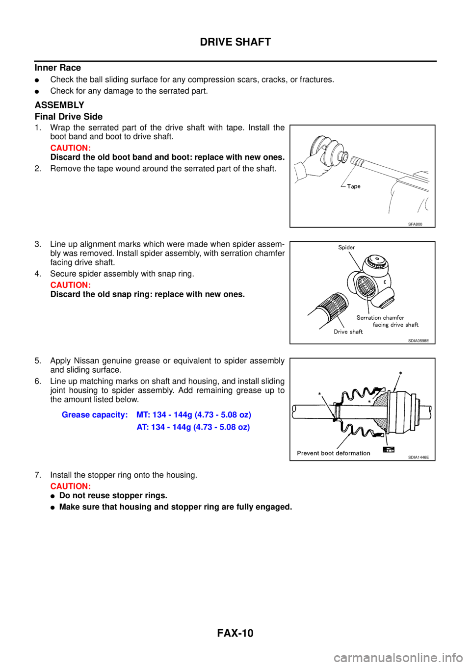
1. Wrap the serrated part of the drive shaft with tape. Install the
boot band and boot to drive shaft.
CAUTION:
Discard the old boot band and boot: replace with new ones.
2. Remove the tape wound around the serrated part of the shaft.
3. Line up alignment marks which were made when spider assem-
bly was removed. Install spider assembly, with serration chamfer
facing drive shaft.
4. Secure spider assembly with snap ring.
CAUTION:
Discard the old snap ring: replace with new ones.
5. Apply Nissan genuine grease or equivalent to spider assembly
and sliding surface.
6. Line up matching marks on shaft and housing, and install sliding
joint housing to spider assembly. Add remaining grease up to
the amount listed below.
7. Install the stopper ring onto the housing.
CAUTION:
lDo not reuse stopper rings.
lMake sure that housing and stopper ring are fully engaged.
SFA800
SDIA0598E
Grease capacity: MT: 134 - 144g (4.73 - 5.08 oz)
AT: 134 - 144g (4.73 - 5.08 oz)
SDIA1446E
Page 1611 of 3171
COIL SPRING AND SHOCK ABSORBER
FSU-11
C
D
F
G
H
I
J
K
L
MA
B
FSU
INSPECTION AFTER DISASSEMBLY
Shock Absorber Assembly
lCheck for smooth operation through a full stroke, both compression and extension.
lCheck for oil leakage on welded or gland packing portions.
lCheck piston rod for cracks, deformation or other damage and replace if necessary.
Mounting Insulator and Rubber Parts
Check cemented rubber-to-metal portion for separation or cracks. Check rubber parts for deterioration and
replace if necessary.
Coil Spring
lCheck for cracks, deformation or other damage and replace if necessary.
ASSEMBLY
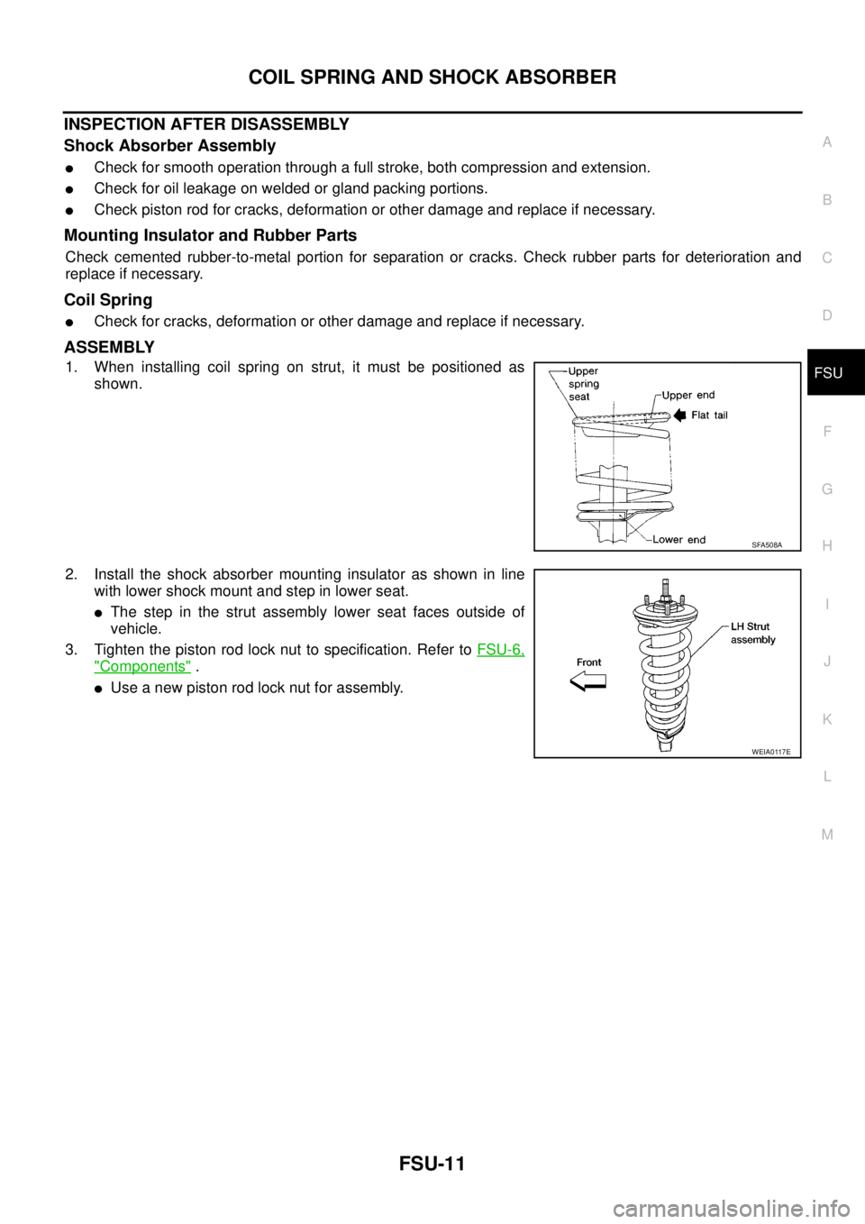
1. When installing coil spring on strut, it must be positioned as
shown.
2. Install the shock absorber mounting insulator as shown in line
with lower shock mount and step in lower seat.
lThe step in the strut assembly lower seat faces outside of
vehicle.
3. Tighten the piston rod lock nut to specification. Refer toFSU-6,
"Components".
lUse a new piston rod lock nut for assembly.
SFA508A
WEIA0117E
Page 2811 of 3171
RSU-6
SHOCK ABSORBER
SHOCK ABSORBER
PFP:56210
Removal and InstallationEES002JI
REMOVAL
1. Support the rear final drive and suspension assembly using a suitable jack.
2. Remove the shock absorber upper and lower nuts and bolts.
3. Remove the shock absorber.
INSPECTION AFTER REMOVAL
lInspect the shock absorber for any oil leaks, cracks, or deformations. Replace the shock absorber as nec-
essary.
lCheck the shock absorber for smooth operation through a full stroke, both compression and extension.
lIf rubber bushings are cracked or deformed, replace rubber bushings.
INSTALLATION
Installation is in the reverse order of removal.
LEIA0115E
Shock absorber upper and lower nuts : Refer toRSU-4, "Components".