2005 NISSAN NAVARA change wheel
[x] Cancel search: change wheelPage 494 of 3171
AV-6
SYSTEM DESCRIPTION
Map-Matching
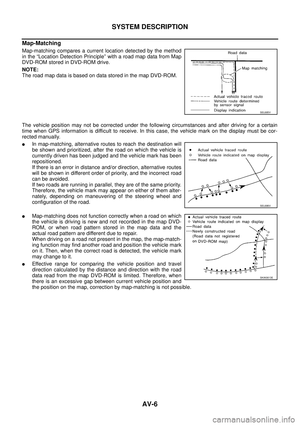
Map-matching compares a current location detected by the method
in the “Location Detection Principle” with a road map data from Map
DVD-ROM stored in DVD-ROM drive.
NOTE:
TheroadmapdataisbasedondatastoredinthemapDVD-ROM.
The vehicle position may not be corrected under the following circumstances and after driving for a certain
time when GPS information is difficult to receive. In this case, the vehicle mark on the display must be cor-
rected manually.
lIn map-matching, alternative routes to reach the destination will
be shown and prioritized, after the road on which the vehicle is
currently driven has been judged and the vehicle mark has been
repositioned.
If there is an error in distance and/or direction, alternative routes
will be shown in different order of priority, and the incorrect road
can be avoided.
If two roads are running in parallel, they are of the same priority.
Therefore, the vehicle mark may appear on either of them alter-
nately, depending on maneuvering of the steering wheel and
configuration of the road.
lMap-matching does not function correctly when a road on which
the vehicle is driving is new and not recorded in the map DVD-
ROM, or when road pattern stored in the map data and the
actual road pattern are different due to repair.
When driving on a road not present in the map, the map-match-
ing function may find another road and position the vehicle mark
on it. Then, when the correct road is detected, the vehicle mark
may change to it.
lEffective range for comparing the vehicle position and travel
direction calculated by the distance and direction with the road
data read from the map DVD-ROM is limited. Therefore, when
there is an excessive gap between current vehicle position and
the position on the map, correction by map-matching is not possible.
SEL685V
SEL686V
SKIA0613E
Page 558 of 3171
AV-70
TROUBLE DIAGNOSIS
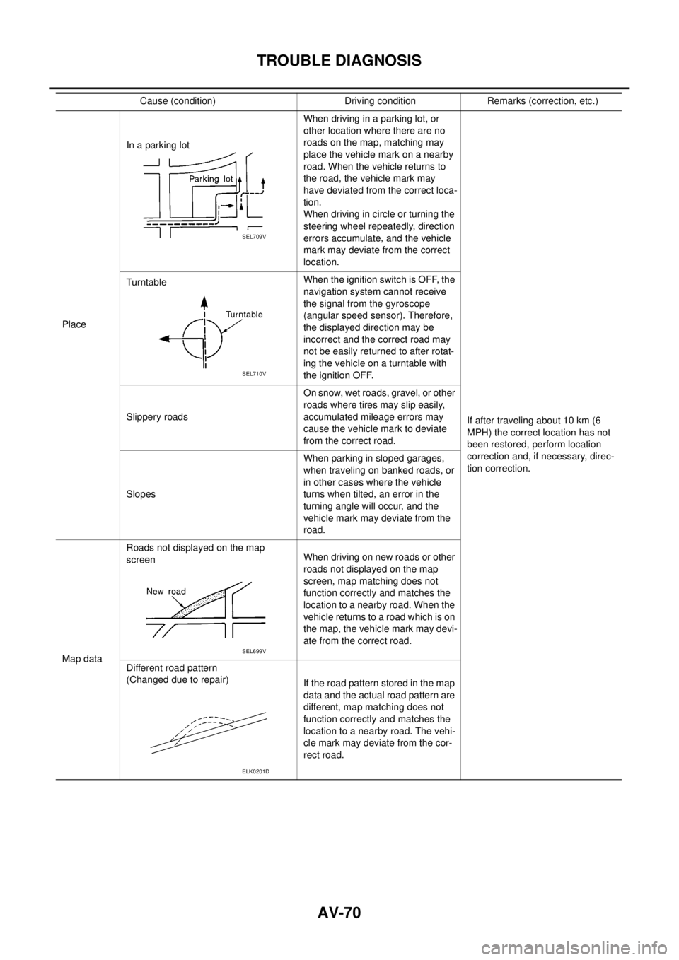
PlaceIn a parking lotWhen driving in a parking lot, or
other location where there are no
roads on the map, matching may
place the vehicle mark on a nearby
road. When the vehicle returns to
the road, the vehicle mark may
have deviated from the correct loca-
tion.
When driving in circle or turning the
steering wheel repeatedly, direction
errors accumulate, and the vehicle
mark may deviate from the correct
location.
If after traveling about 10 km (6
MPH) the correct location has not
been restored, perform location
correction and, if necessary, direc-
tion correction. TurntableWhentheignitionswitchisOFF,the
navigation system cannot receive
the signal from the gyroscope
(angular speed sensor). Therefore,
the displayed direction may be
incorrect and the correct road may
not be easily returned to after rotat-
ing the vehicle on a turntable with
the ignition OFF.
Slippery roadsOn snow, wet roads, gravel, or other
roads where tires may slip easily,
accumulated mileage errors may
cause the vehicle mark to deviate
from the correct road.
SlopesWhen parking in sloped garages,
when traveling on banked roads, or
in other cases where the vehicle
turns when tilted, an error in the
turning angle will occur, and the
vehicle mark may deviate from the
road.
Map dataRoads not displayed on the map
screenWhen driving on new roads or other
roads not displayed on the map
screen, map matching does not
function correctly and matches the
location to a nearby road. When the
vehicle returns to a road which is on
the map, the vehicle mark may devi-
ate from the correct road.
Different road pattern
(Changed due to repair)
If the road pattern stored in the map
data and the actual road pattern are
different, map matching does not
function correctly and matches the
location to a nearby road. The vehi-
cle mark may deviate from the cor-
rect road. Cause (condition) Driving condition Remarks (correction, etc.)
SEL709V
SEL710V
SEL699V
ELK0201D
Page 560 of 3171

AV-72
TROUBLE DIAGNOSIS
–Because calculation of the current location cannot be done when traveling with the ignition OFF, for exam-
ple when traveling by ferry or when being towed, the location before travel is displayed. If the precise loca-
tioncanbedetectedwithGPS,thelocationwillbecorrected.
THE CURRENT POSITION MARK JUMPS.
In the following cases, the current location mark may appear to jump as a result of automatic correction of the
current location.
lWhen map matching has been done
–If current location and the current location mark are different when map matching is done, the current
location mark may seem to jump. At this time, the location may be “corrected” to the incorrect road or to a
location which is not on a road.
lWhen GPS location correction has been done
–If current location and the current location mark are different when location is corrected using GPS mea-
surements, the current location mark may seem to jump. At this time, the location may be “corrected” to a
location which is not on a road.
THE CURRENT LOCATION MARK IS IN A RIVER OR THE SEA.
The navigation system moves the current location mark with no distinction between land and rivers or sea. If
the location mark is somehow out of place, it may appear that the vehicle is driving in a river or the sea.
CURRENT LOCATION MARK ROTATES WITHOUT OPERATION
If the ignition switch is turned ON with the turntable rotating, the rotating condition is recorded as the stop con-
dition. Therefore, the current location mark might rotate when actually stopping.
WHEN DRIVING ON THE SAME ROAD, SOMETIMES THE CURRENT LOCATION MARK IS IN
THE CORRECT PLACE AND SOMETIMES IT IS IN THE INCORRECT PLACE.
The conditions of the GPS antenna (GPS data) and gyroscope (angular speed sensor) change gradually.
Depending on the road traveled and operation of the steering wheel, the location detection results will be dif-
ferent. Therefore, even on a road on which the location has never been incorrect, conditions may cause the
vehicle mark to deviate.
LOCATION CORRECTION BY MAP MATCHING IS SLOW.
lThe map matching function needs to refer to the data of the surrounding area. It is necessary to drive
some distance for the function to work.
lBecause of the way map matching operates, when there are many roads running in similar directions in
the surrounding area a matching determination may be impossible. The location will remain uncorrected
until some special feature is found.
ALTHOUGH THE GPS RECEIVING DISPLAY IS GREEN, THE VEHICLE MARK DOES NOT
RETURN TO THE CORRECT LOCATION.
lGPS accuracy has a malfunction range of about 10 m. In some cases the current location mark may not
be on the correct street, even when GPS location correction is done.
lThe navigation system compares the results of GPS location detection with the results from map-match-
ing location detection. The one that is determined to have higher accuracy is used.
lPosition correction by GPS is not available while the vehicle is stopped.
THE NAME OF THE CURRENT PLACE IS NOT DISPLAYED.
The current place name might not be displayed when there is no name of place information in the map screen.
THE DISPLAY IS DIFFERENT BETWEEN BIRDVIEW®AND (FLAT) MAP DISPLAY.
The following is different at birdview®.
lThe current place name displays names that are primarily in the direction of vehicle travel.
lThe amount of time before the vehicle travel or turn angle is updated on the screen is longer than for the
(flat) map display.
lThe conditions for display of place names, roads, and other data are different for nearby areas and for
more distant areas.
lSome trimming of the character data is done to prevent the display from becoming too complex. In some
cases and in some locations, the display contents may differ.
lThe same place name, street name, etc. may be displayed multiple times.
Page 915 of 3171
COMBINATION METERS
DI-5
C
D
E
F
G
H
I
J
L
MA
B
DI
FUEL GAUGE
The fuel gauge indicates the approximate fuel level in the fuel tank.
Combination meter reads a resistor signal from fuel level sensor unit.
Signal is supplied
lto combination meter terminal 9
lthrough fuel level sensor unit terminal 1 and 2
lfrom combination meter terminal 4.
ODO/TRIP METER
lABS actuator and electric unit (control unit) converses a pulse signal from wheel sensor to vehicle speed
signal, and transmits vehicle speed signal to combination meter with CAN communication.
lCombination meter uses the vehicle speed signal to calculate the mileage, and it displays.
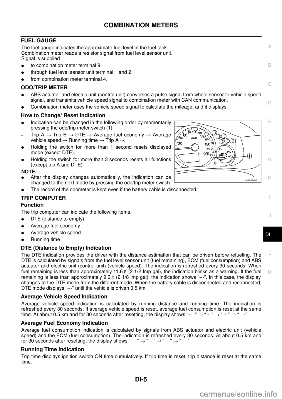
How to Change/ Reset Indication
lIndication can be changed in the following order by momentarily
pressing the odo/trip meter switch (1).
–Trip A®Trip B®DTE®Average fuel economy®Average
vehicle speed®Running time®Trip A ···.
lHolding the switch for more than 1 second resets displayed
mode (except DTE).
lHolding the switch for more than 3 seconds resets all functions
(except trip A and DTE).
NOTE:
lAfter the display changes automatically, the indication can be
changed to the next mode by pressing the odo/trip meter switch.
lThe record of the odometer is kept even if the battery cable is disconnected.
TRIP COMPUTER
Function
The trip computer can indicate the following items.
lDTE (distance to empty)
lAverage fuel economy
lAverage vehicle speed
lRunning time
DTE (Distance to Empty) Indication
The DTE indication provides the driver with the distance estimation that can be driven before refueling. The
DTE is calculated by signals from the fuel level sensor unit (fuel remaining), ECM (fuel consumption) and ABS
actuator and electric unit (control unit) (vehicle speed). The indication is refreshed every 30 seconds. When
fuel remaining is less than approximately 11.6 (2 1/2 Imp gal), the indication blinks as a warning. If the fuel
remaining is less than approximately 9.6 (2 1/8 Imp gal), the indication shows “---”. In this case, the display
changes to the DTE mode from the different mode. When the battery cable is disconnected and reconnected,
DTE mode displays “---” until the vehicle is driven 0.5 km.
Average Vehicle Speed Indication
Average vehicle speed indication is calculated by running distance and running time. The indication is
refreshed every 30 seconds. If average vehicle speed is reset, average fuel consumption is reset at the same
time. At about 0.5 km and for 30 seconds after resetting, the display shows “- ”®“- ”®“-”®“ -”.
Average Fuel Economy Indication
Average fuel consumption indication is calculated by signals from ABS actuator and electric unit (vehicle
speed) and the ECM (fuel consumption). The indication is refreshed every 30 seconds. At about 0.5 km and
for 30 seconds after resetting, the display shows “- ”®“- ”®“-”®“ -”.
Running Time Indication
Trip time displays ignition switch ON time cumulatively. If trip time is reset, trip distance is reset at the same
time.
SKIB4848E
Page 999 of 3171
ENGINE CONTROL SYSTEM
EC-19
C
D
E
F
G
H
I
J
K
L
MA
EC
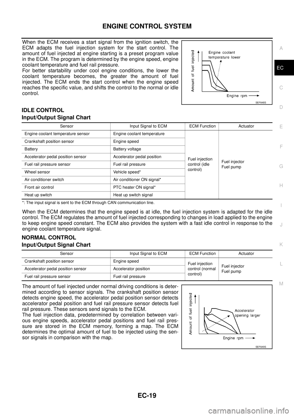
When the ECM receives a start signal from the ignition switch, the
ECM adapts the fuel injection system for the start control. The
amount of fuel injected at engine starting is a preset program value
in the ECM. The program is determined by the engine speed, engine
coolant temperature and fuel rail pressure.
For better startability under cool engine conditions, the lower the
coolant temperature becomes, the greater the amount of fuel
injected. The ECM ends the start control when the engine speed
reaches the specific value, and shifts the control to the normal or idle
control.
IDLE CONTROL
Input/Output Signal Chart
*: The input signal is sent to the ECM through CAN communication line.
When the ECM determines that the engine speed is at idle, the fuel injection system is adapted for the idle
control. The ECM regulates the amount of fuel injected corresponding to changes in load applied to the engine
to keep engine speed constant. The ECM also provides the system with a fast idle control in response to the
engine coolant temperature signal.
NORMAL CONTROL
Input/Output Signal Chart
The amount of fuel injected under normal driving conditions is deter-
mined according to sensor signals. The crankshaft position sensor
detects engine speed, the accelerator pedal position sensor detects
accelerator pedal position and fuel rail pressure sensor detects fuel
rail pressure. These sensors send signals to the ECM.
The fuel injection data, predetermined by correlation between vari-
ous engine speeds, accelerator pedal positions and fuel rail pres-
sure are stored in the ECM memory, forming a map. The ECM
determines the optimal amount of fuel to be injected using the sen-
sor signals in comparison with the map.
SEF648S
Sensor Input Signal to ECM ECM Function Actuator
Engine coolant temperature sensor Engine coolant temperature
Fuel injection
control (idle
control)Fuel injector
Fuel pump Crankshaft position sensor Engine speed
Battery Battery voltage
Accelerator pedal position sensor Accelerator pedal position
Fuel rail pressure sensor Fuel rail pressure
Wheel sensor Vehicle speed*
Air conditioner switch Air conditioner ON signal*
Front air control PTC heater ON signal*
Heat up switch Heat up switch signal
Sensor Input Signal to ECM ECM Function Actuator
Crankshaft position sensor Engine speed
Fuel injection
control (normal
control)Fuel injector
Fuel pump Accelerator pedal position sensor Accelerator position
Fuel rail pressure sensor Fuel rail pressure
SEF649S
Page 1163 of 3171
DTC P0501 ASCD VEHICLE SPEED SENSOR
EC-183
C
D
E
F
G
H
I
J
K
L
MA
EC
DTC P0501 ASCD VEHICLE SPEED SENSORPFP:24810
Component DescriptionEBS01KHH
The ECM receives vehicle speed sensor signal via CAN communication line. It is sent from combination
meter. The ECM uses this signal for ASCD control. Refer toEC-355, "
AUTOMATIC SPEED CONTROL
DEVICE (ASCD)"for ASCD functions.
On Board Diagnosis LogicEBS01KHI
The MI will not light up for this self-diagnosis.
NOTE:
lIf DTC P0501 is displayed with DTC U1000 first perform the trouble diagnosis for DTC U1000. Refer
toEC-79, "
DTC U1000 CAN COMMUNICATION LINE".
lIf DTC P0501 is displayed with DTC P0606, first perform the trouble diagnosis for DTC P0606.
Refer toEC-215, "
DTC P0606 ECM".
DTC Confirmation ProcedureEBS01KHJ
CAUTION:
Always drive vehicle at a safe speed.
NOTE:
If DTC Confirmation Procedure has been previously conducted, always turn ignition switch OFF and wait at
least 10 seconds before conducting the next test.
TESTING CONDITION:
Step 3 may be conducted with the drive wheels lifted in the shop or by driving the vehicle. If a road test
is expected to be easier, it is unnecessary to lift the vehicle.
WITH CONSULT-II
1. Start engine.
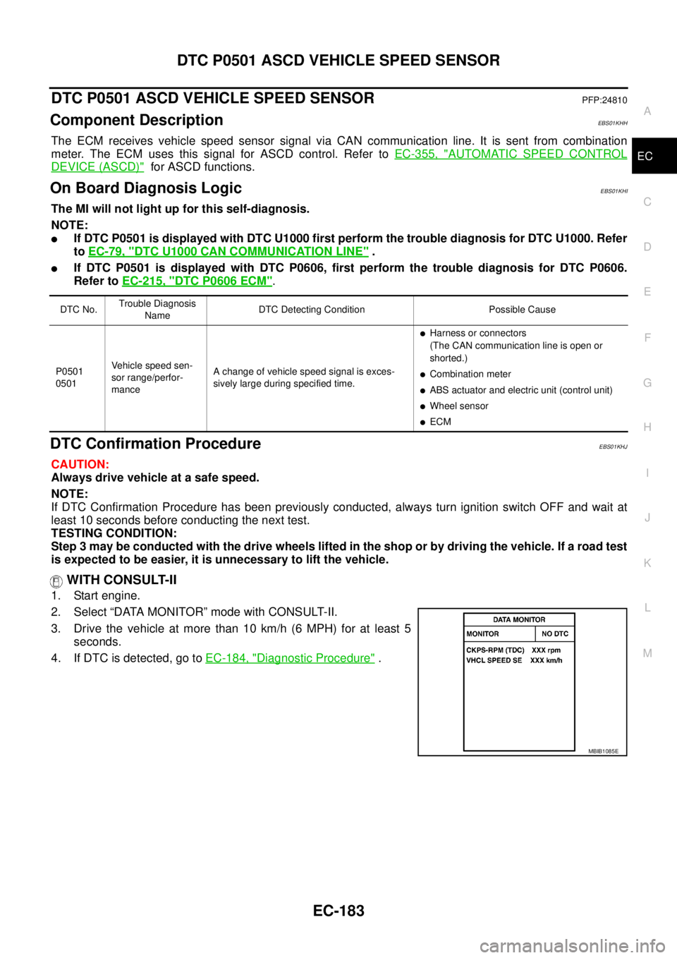
2. Select “DATA MONITOR” mode with CONSULT-II.
3. Drive the vehicle at more than 10 km/h (6 MPH) for at least 5
seconds.
4. If DTC is detected, go toEC-184, "
Diagnostic Procedure".
DTC No.Trouble Diagnosis
NameDTC Detecting Condition Possible Cause
P0501
0501Vehicle speed sen-
sor range/perfor-
manceA change of vehicle speed signal is exces-
sively large during specified time.
lHarness or connectors
(The CAN communication line is open or
shorted.)
lCombination meter
lABS actuator and electric unit (control unit)
lWheel sensor
lECM
SEF058YMBIB1085E
Page 1608 of 3171
FSU-8
ON-VEHICLE SERVICE
CAMBER AND CASTER
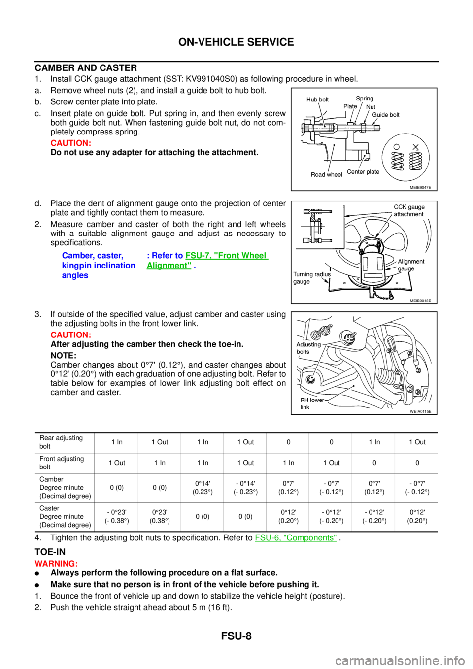
1. Install CCK gauge attachment (SST: KV991040S0) as following procedure in wheel.
a. Remove wheel nuts (2), and install a guide bolt to hub bolt.
b. Screw center plate into plate.
c. Insert plate on guide bolt. Put spring in, and then evenly screw
both guide bolt nut. When fastening guide bolt nut, do not com-
pletely compress spring.
CAUTION:
Do not use any adapter for attaching the attachment.
d. Place the dent of alignment gauge onto the projection of center
plate and tightly contact them to measure.
2. Measure camber and caster of both the right and left wheels
with a suitable alignment gauge and adjust as necessary to
specifications.
3. If outside of the specified value, adjust camber and caster using
the adjusting bolts in the front lower link.
CAUTION:
After adjusting the camber then check the toe-in.
NOTE:
Camber changes about 0°7' (0.12°), and caster changes about
0°12' (0.20°) with each graduation of one adjusting bolt. Refer to
table below for examples of lower link adjusting bolt effect on
camber and caster.
4. Tighten the adjusting bolt nuts to specification. Refer toFSU-6, "
Components".
TOE-IN
WARNING:
lAlways perform the following procedure on a flat surface.
lMake sure that no person is in front of the vehicle before pushing it.
1. Bounce the front of vehicle up and down to stabilize the vehicle height (posture).
2. Push the vehicle straight ahead about 5 m (16 ft).
MEIB9047E
Camber, caster,
kingpin inclination
angles:RefertoFSU-7, "Front Wheel
Alignment".
MEIB9048E
WEIA0115E
Rear adjusting
bolt1In 1Out 1In 1Out 0 0 1In 1Out
Front adjusting
bolt1Out 1In 1In 1Out 1In 1Out 0 0
Camber
Degree minute
(Decimal degree)0(0) 0(0)0°14'
(0.23°)-0°14'
(- 0.23°)0°7'
(0.12°)-0°7'
(- 0.12°)0°7'
(0.12°)-0°7'
(- 0.12°)
Caster
Degree minute
(Decimal degree)-0°23'
(- 0.38°)0°23'
(0.38°)0(0) 0(0)0°12'
(0.20°)-0°12'
(- 0.20°)-0°12'
(- 0.20°)0°12'
(0.20°)
Page 2282 of 3171
GENERAL MAINTENANCE
MA-7
C
D
E
F
G
H
I
J
K
MA
B
MA
GENERAL MAINTENANCEPFP:00000
General MaintenanceELS001HT
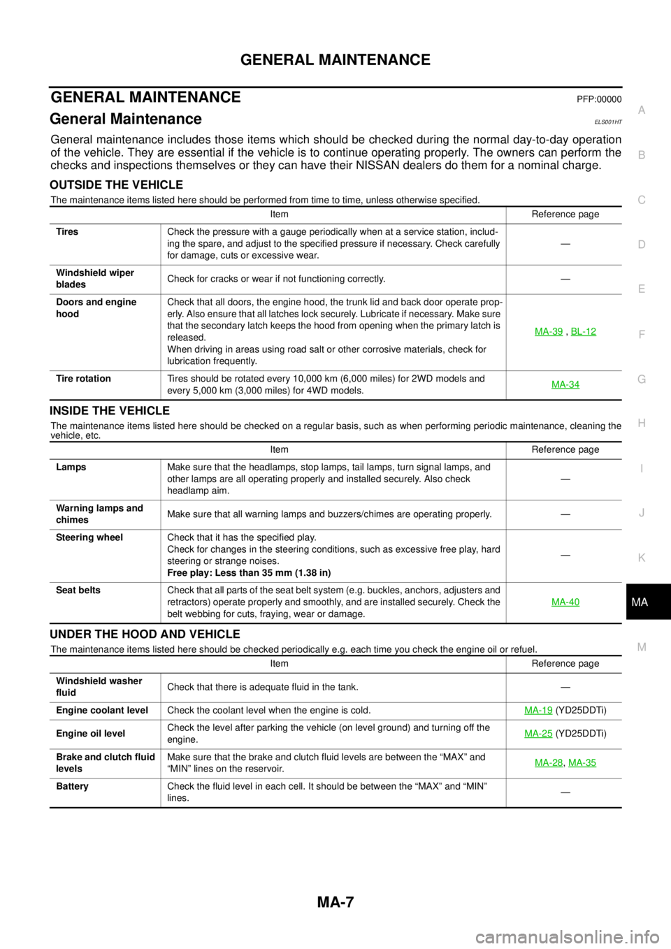
General maintenance includes those items which should be checked during the normal day-to-day operation
of the vehicle. They are essential if the vehicle is to continue operating properly. The owners can perform the
checks and inspections themselves or they can have their NISSAN dealers do them for a nominal charge.
OUTSIDE THE VEHICLE
The maintenance items listed here should be performed from time to time, unless otherwise specified.
INSIDE THE VEHICLE
The maintenance items listed here should be checked on a regular basis, such as when performing periodic maintenance, cleaning the
vehicle, etc.
UNDER THE HOOD AND VEHICLE
The maintenance items listed here should be checked periodically e.g. each time you check the engine oil or refuel.Item Reference page
TiresCheck the pressure with a gauge periodically when at a service station, includ-
ing the spare, and adjust to the specified pressure if necessary. Check carefully
for damage, cuts or excessive wear.—
Windshield wiper
bladesCheck for cracks or wear if not functioning correctly. —
Doors and engine
hoodCheck that all doors, the engine hood, the trunk lid and back door operate prop-
erly. Also ensure that all latches lock securely. Lubricate if necessary. Make sure
that the secondary latch keeps the hood from opening when the primary latch is
released.
When driving in areas using road salt or other corrosive materials, check for
lubrication frequently.MA-39
,BL-12
Tire rotationTires should be rotated every 10,000 km (6,000 miles) for 2WD models and
every 5,000 km (3,000 miles) for 4WD models.MA-34
Item Reference page
LampsMake sure that the headlamps, stop lamps, tail lamps, turn signal lamps, and
other lamps are all operating properly and installed securely. Also check
headlamp aim.—
Warning lamps and
chimesMake sure that all warning lamps and buzzers/chimes are operating properly. —
Steering wheelCheck that it has the specified play.
Check for changes in the steering conditions, such as excessive free play, hard
steering or strange noises.
Free play: Less than 35 mm (1.38 in)—
Seat beltsCheck that all parts of the seat belt system (e.g. buckles, anchors, adjusters and
retractors) operate properly and smoothly, and are installed securely. Check the
belt webbing for cuts, fraying, wear or damage.MA-40
Item Reference page
Windshield washer
fluidCheck that there is adequate fluid in the tank. —
Engine coolant levelCheck the coolant level when the engine is cold.MA-19
(YD25DDTi)
Engine oil levelCheck the level after parking the vehicle (on level ground) and turning off the
engine.MA-25
(YD25DDTi)
Brake and clutch fluid
levelsMake sure that the brake and clutch fluid levels are between the “MAX” and
“MIN” lines on the reservoir.MA-28
,MA-35
BatteryCheck the fluid level in each cell. It should be between the “MAX” and “MIN”
lines.—