2005 NISSAN NAVARA suspension
[x] Cancel search: suspensionPage 1 of 3171
MODELD40 SERIES
2005 NISSAN EUROPE S.A.S.
All rights reserved. No part of this Electronic Service Manual may be reproduced or stored in a retrieval system, or transmitted in any
form, or by any means, electronic, mechanical, photocopying, recording or otherwise, without the prior written permission of Nissan
Europe S.A.S., Paris, France.
A GENERAL INFORMATION
B ENGINE
C TRANSMISSION/TRANSAXLE
D DRIVELINE/AXLE
E SUSPENSION F BRAKES
G STEERING H RESTRAINTS
I BODY
J AIR CONDITIONER
K ELECTRICAL
L MAINTENANCE
M INDEXGI General Information
EM Engine Mechanical
LU Engine Lubrication System
CO Engine Cooling System
EC Engine Control System
FL Fuel System
EX Exhaust System
ACC Accelerator Control System
CL Clutch
MTManualTransmission
AT Automatic Transmission
TF Transfer
PR Propeller Shaft
FFD Front Final Drive
RFD Rear Final Drive
FAX Front Axle
RAX Rear Axle
FSU Front Suspension
RSU Rear Suspension
WT Road Wheels & Tires
BR Brake System
PB Parking Brake System
BRC Brake Control System
PS Power Steering System
SB Seat Belts
SRS Supplemental Restraint System (SRS)
BL Body, Lock & Security System
GW Glasses, Window System & Mirrors
RF Roof
EI Exterior & Interior
IP Instrument Panel
SE Seat
ATC Automatic Air Conditioner
MTC Manual Air Conditioner
SC Starting & Charging System
LT Lighting System
DI Driver Information System
WW Wiper, Washer & Horn
BCS Body Control System
LAN LAN System
AV Audio, Visual & Telephone System
ACS Auto Cruise Control System
PG Power Supply, Ground & Circuit Elements
MA Maintenance
IDX Alphabetical Index
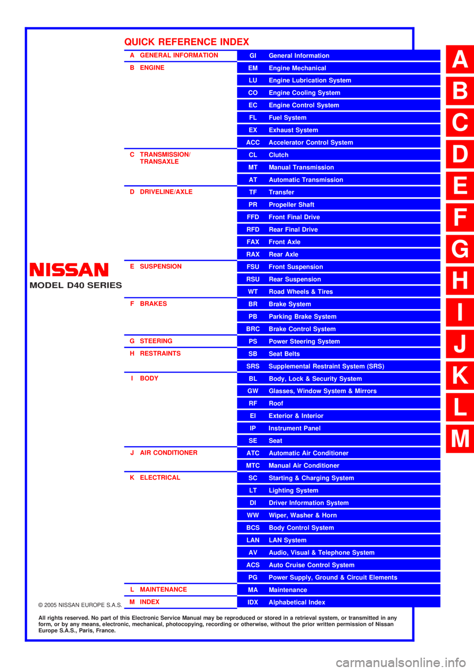
QUICK REFERENCE INDEX
A
B
C
D
E
F
G
H
I
J
K
L
M
Page 791 of 3171
NOISE, VIBRATION AND HARSHNESS (NVH) TROUBLESHOOTING
BR-5
C
D
E
G
H
I
J
K
L
MA
B
BR
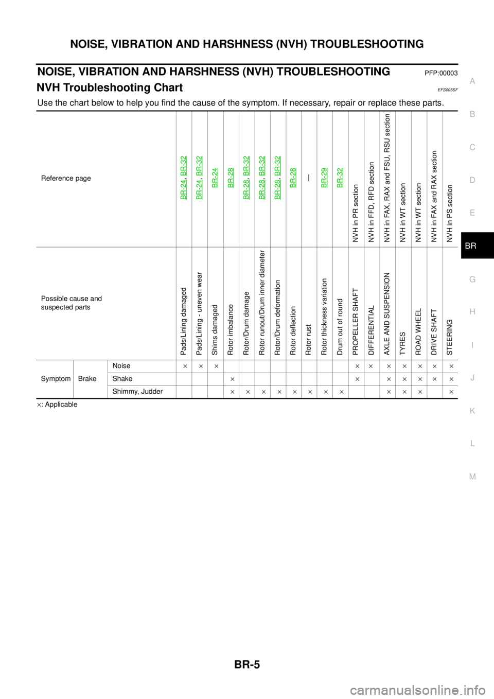
NOISE, VIBRATION AND HARSHNESS (NVH) TROUBLESHOOTINGPFP:00003
NVH Troubleshooting ChartEFS005SF
Use the chart below to help you find the cause of the symptom. If necessary, repair or replace these parts.
´: Applicable Reference page
BR-24
,BR-32
BR-24
,BR-32BR-24BR-28
BR-28
,BR-32
BR-28
,BR-32
BR-28
,BR-32BR-28—
BR-29BR-32
NVHinPRsection
NVH in FFD, RFD section
NVH in FAX, RAX and FSU, RSU section
NVH in WT section
NVH in WT section
NVH in FAX and RAX section
NVH in PS section
Possible cause and
suspected parts
Pads/Lining damaged
Pads/Lining - uneven wear
Shims damaged
Rotor imbalance
Rotor/Drum damage
Rotor runout/Drum inner diameter
Rotor/Drum deformation
Rotor deflection
Rotor rust
Rotor thickness variation
Drum out of round
PROPELLER SHAFT
DIFFERENTIAL
AXLE AND SUSPENSION
TYRES
ROAD WHEEL
DRIVE SHAFT
STEERING
Symptom BrakeNoise´´´ ´´ ´´´
´´
Shake´´´´´
´´
Shimmy, Judder´´´´´´´´ ´´´ ´
Page 802 of 3171
BR-16
LOAD SENSING VALVE
Inspection
EFS006A8
INSPECTION
1. With the vehicle in unladen condition, a person should sit in driver's seat at the rear. Then he/she should
get out of car gently. (This is to stabilize suspension deflection.)
NOTE:
“Unladen condition”: with full coolant, lubricant, 6 to 8 litters of fuel, spare tyre, jack, and hand tools
loaded.
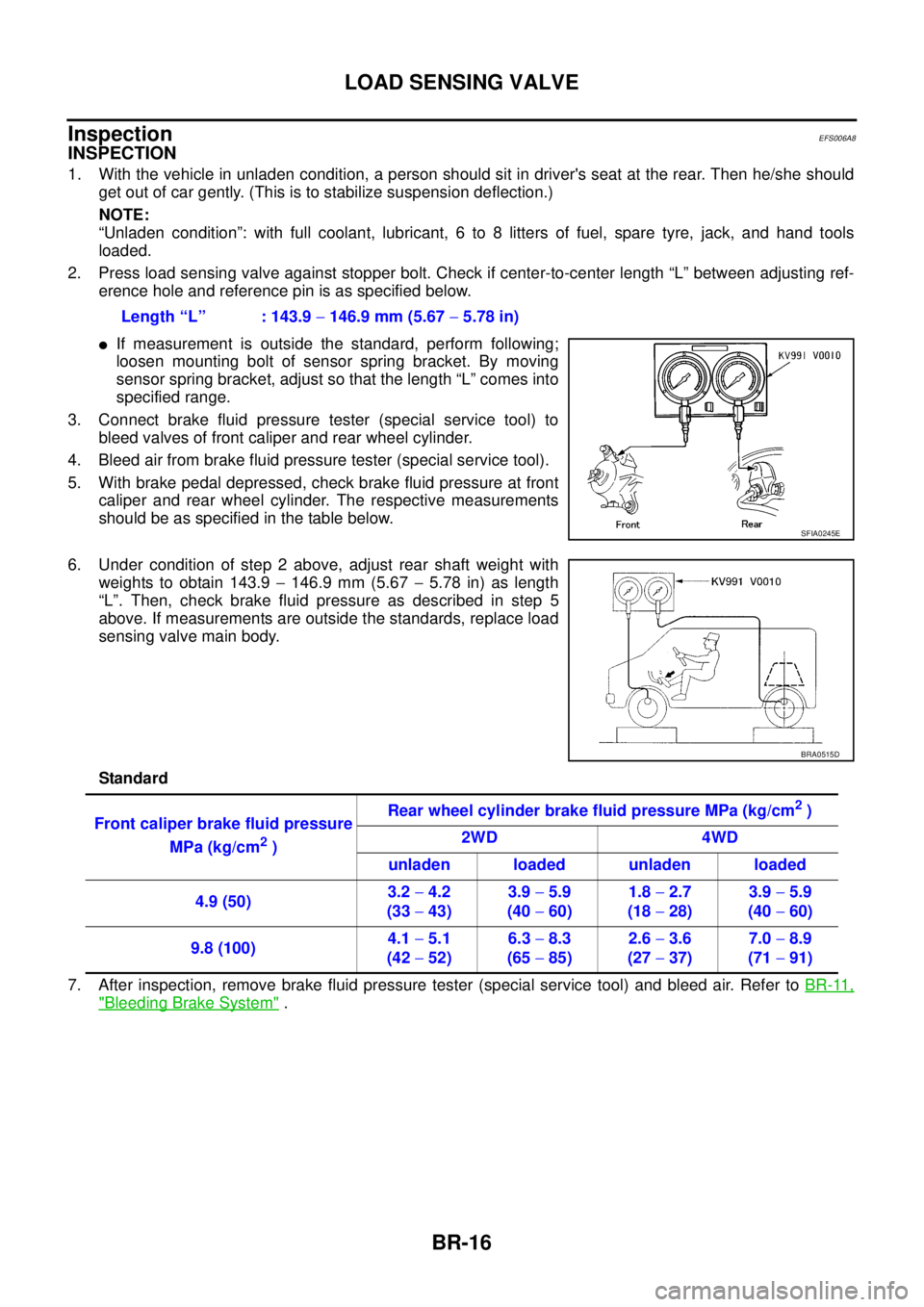
2. Press load sensing valve against stopper bolt. Check if center-to-center length “L” between adjusting ref-
erence hole and reference pin is as specified below.
lIf measurement is outside the standard, perform following;
loosen mounting bolt of sensor spring bracket. By moving
sensor spring bracket, adjust so that the length “L” comes into
specified range.
3. Connect brake fluid pressure tester (special service tool) to
bleed valves of front caliper and rear wheel cylinder.
4. Bleed air from brake fluid pressure tester (special service tool).
5. With brake pedal depressed, check brake fluid pressure at front
caliper and rear wheel cylinder. The respective measurements
should be as specified in the table below.
6. Under condition of step 2 above, adjust rear shaft weight with
weights to obtain 143.9-146.9 mm (5.67-5.78 in) as length
“L”. Then, check brake fluid pressure as described in step 5
above. If measurements are outside the standards, replace load
sensing valve main body.
Standard
7. After inspection, remove brake fluid pressure tester (special service tool) and bleed air. Refer toBR-11,
"Bleeding Brake System". Length “L” : 143.9-146.9 mm (5.67-5.78 in)
SFIA0245E
BRA0515D
Front caliper brake fluid pressure
MPa (kg/cm
2)Rear wheel cylinder brake fluid pressure MPa (kg/cm
2)
2WD 4WD
unladen loaded unladen loaded
4.9 (50)3.2-4.2
(33-43)3.9-5.9
(40-60)1.8-2.7
(18-28)3.9-5.9
(40-60)
9.8 (100)4.1-5.1
(42-52)6.3-8.3
(65-85)2.6-3.6
(27-37)7.0-8.9
(71-91)
Page 1536 of 3171
FAX-4
NOISE, VIBRATION, AND HARSHNESS (NVH) TROUBLESHOOTING
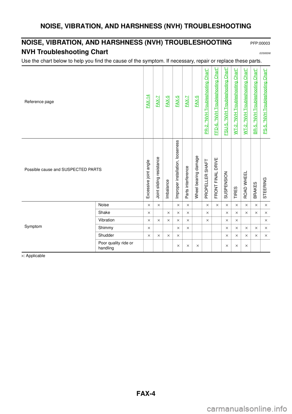
NOISE, VIBRATION, AND HARSHNESS (NVH) TROUBLESHOOTING
PFP:00003
NVH Troubleshooting ChartEDS003I6
Use the chart below to help you find the cause of the symptom. If necessary, repair or replace these parts.
´: ApplicableReference page
FAX-14FAX-7FAX-5FAX-5FAX-7FAX-5
PR-2, "
NVH Troubleshooting Chart
"
FFD-6, "
NVH Troubleshooting Chart
"
FSU-5, "
NVH Troubleshooting Chart
"
WT-2, "
NVH Troubleshooting Chart
"
WT-2, "
NVH Troubleshooting Chart
"
BR-5, "
NVH Troubleshooting Chart
"
PS-5, "
NVH Troubleshooting Chart
"
Possible cause and SUSPECTED PARTS
Excessive joint angle
Joint sliding resistance
Imbalance
Improper installation, looseness
Parts interference
Wheel bearing damage
PROPELLER SHAFT
FRONT FINAL DRIVE
SUSPENSION
TIRES
ROAD WHEEL
BRAKES
STEERING
SymptomNoise´´ ´´ ´´´´´´´
Shake´ ´´´ ´ ´´´´´
Vibration´´´´´ ´ ´´ ´
Shimmy´ ´´ ´´´´´
Shudder´´´´ ´´´´´
Poor quality ride or
handling´´´ ´´´
Page 1552 of 3171
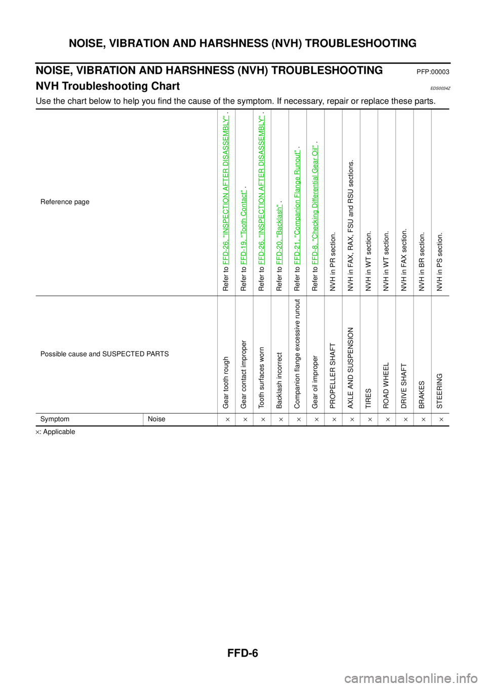
FFD-6
NOISE, VIBRATION AND HARSHNESS (NVH) TROUBLESHOOTING
NOISE, VIBRATION AND HARSHNESS (NVH) TROUBLESHOOTING
PFP:00003
NVH Troubleshooting ChartEDS0034Z
Use the chart below to help you find the cause of the symptom. If necessary, repair or replace these parts.
´: ApplicableReference page
Refer toFFD-26, "
INSPECTION AFTER DISASSEMBLY
".
Refer toFFD-19, "
To o t h C o n t a c t
".
Refer toFFD-26, "
INSPECTION AFTER DISASSEMBLY
".
Refer toFFD-20, "
Backlash
".
Refer toFFD-21, "
Companion Flange Runout
".
Refer toFFD-8, "
Checking Differential Gear Oil
".
NVH in PR section.
NVH in FAX, RAX, FSU and RSU sections.
NVH in WT section.
NVH in WT section.
NVH in FAX section.
NVH in BR section.
NVH in PS section.
Possible cause and SUSPECTED PARTS
Gear tooth rough
Gear contact improper
Tooth surfaces worn
Backlash incorrect
Companion flange excessive runout
Gear oil improper
PROPELLER SHAFT
AXLE AND SUSPENSION
TIRES
ROAD WHEEL
DRIVE SHAFT
BRAKES
STEERING
Symptom Noise´´´´´´´´´´´´´
Page 1601 of 3171

FSU-1
FRONT SUSPENSION
E SUSPENSION
CONTENTS
C
D
F
G
H
I
J
K
L
M
SECTIONFSU
A
B
FSU
FRONT SUSPENSION
PRECAUTIONS .......................................................... 2
Precautions .............................................................. 2
PREPARATION ........................................................... 3
Special Service Tools ............................................... 3
Commercial Service Tools ........................................ 4
NOISE, VIBRATION, AND HARSHNESS (NVH)
TROUBLESHOOTING ................................................ 5
NVH Troubleshooting Chart ..................................... 5
FRONT SUSPENSION ASSEMBLY ........................... 6
Components ............................................................. 6
ON-VEHICLE SERVICE ............................................. 7
Front Suspension Parts ............................................ 7
Front Wheel Alignment ............................................. 7
PRELIMINARY INSPECTION ............................... 7
CAMBER AND CASTER ....................................... 8
TOE-IN .................................................................. 8
FRONT WHEEL TURNING ANGLE ..................... 9
COIL SPRING AND SHOCK ABSORBER ............... 10
Removal and Installation ........................................ 10
REMOVAL ........................................................... 10
INSTALLATION ................................................... 10
Disassembly and Assembly ................................... 10
DISASSEMBLY ................................................... 10
INSPECTION AFTER DISASSEMBLY ................ 11
ASSEMBLY .......................................................... 11
STABILIZER BAR ..................................................... 12
Removal and Installation ........................................ 12
REMOVAL ........................................................... 12
INSPECTION AFTER REMOVAL ....................... 12
INSTALLATION ................................................... 12UPPER LINK ............................................................. 13
Removal and Installation ........................................ 13
REMOVAL ........................................................... 13
INSPECTION AFTER REMOVAL ....................... 13
INSTALLATION ................................................... 13
LOWER LINK ............................................................ 14
Removal and Installation ........................................ 14
REMOVAL ........................................................... 14
INSPECTION AFTER REMOVAL ....................... 14
INSTALLATION ................................................... 14
UPPER BALL JOINT AND LOWER BALL JOINT ... 15
Removal and Installation ........................................ 15
Inspection ............................................................... 15
SWINGING FORCE ............................................ 15
TURNING FORCE .............................................. 15
VERTICAL END PLAY ........................................ 15
KNUCKLE ................................................................. 16
On-Vehicle Inspection and Service ......................... 16
Removal and Installation ........................................ 16
REMOVAL ........................................................... 16
INSPECTION AFTER REMOVAL ....................... 17
INSTALLATION ................................................... 18
SERVICE DATA AND SPECIFICATIONS (SDS) ...... 19
General Specifications (Front) ................................ 19
Wheel Alignment (Unladen*
1) ................................ 19
Ball Joint ................................................................. 20
Wheelarch Height (Unladen*
1) .............................. 21
Page 1602 of 3171

FSU-2
PRECAUTIONS
PRECAUTIONS
PFP:00001
PrecautionsEES002KG
lWhen installing the rubber bushings, the final tightening must be done under unladen condition and with
the tires on level ground. Oil will shorten the life of the rubber bushings, so wipe off any spilled oil immedi-
ately.
lUnladen condition means the fuel tank, engine coolant and lubricants are at the full specification. The
spare tire, jack, hand tools, and mats are in their designated positions.
lAfter installing suspension components, check the wheel alignment.
lLock nuts are not reusable. Always use new lock nuts for installation. New lock nuts are pre-oiled, do not
apply any additional lubrication.
Page 1605 of 3171
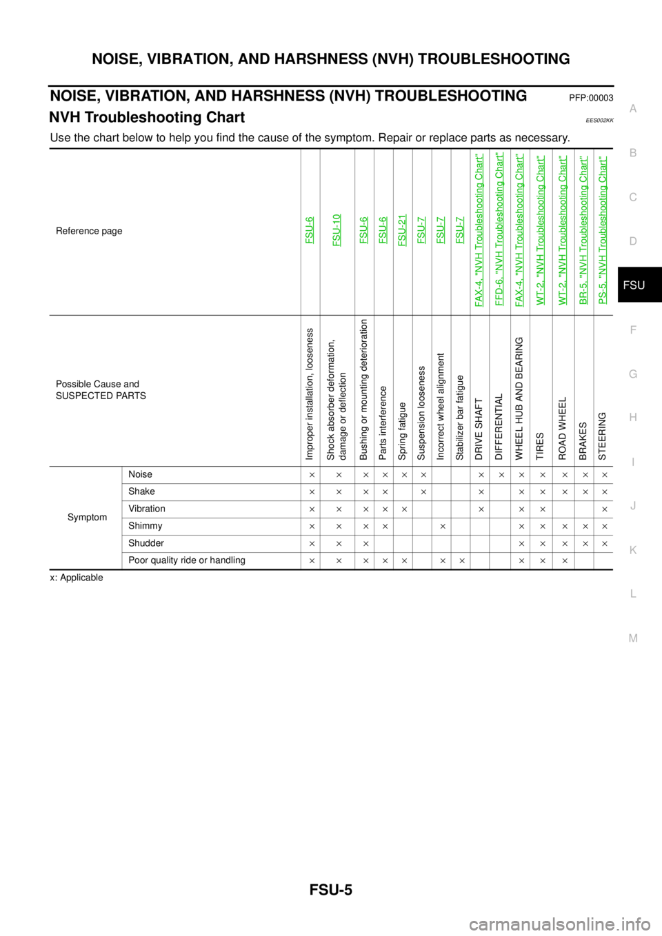
NOISE, VIBRATION, AND HARSHNESS (NVH) TROUBLESHOOTING
FSU-5
C
D
F
G
H
I
J
K
L
MA
B
FSU
NOISE, VIBRATION, AND HARSHNESS (NVH) TROUBLESHOOTINGPFP:00003
NVH Troubleshooting ChartEES002KK
Use the chart below to help you find the cause of the symptom. Repair or replace parts as necessary.
x: ApplicableReference page
FSU-6FSU-10FSU-6FSU-6FSU-21FSU-7FSU-7FSU-7
FAX-4, "
NVH Troubleshooting Chart
"
FFD-6, "
NVH Troubleshooting Chart
"
FAX-4, "
NVH Troubleshooting Chart
"
WT-2, "
NVH Troubleshooting Chart
"
WT-2, "
NVH Troubleshooting Chart
"
BR-5, "
NVH Troubleshooting Chart
"
PS-5, "
NVH Troubleshooting Chart
"
Possible Cause and
SUSPECTED PARTS
Improper installation, looseness
Shock absorber deformation,
damage or deflection
Bushing or mounting deterioration
Parts interference
Spring fatigue
Suspension looseness
Incorrect wheel alignment
Stabilizer bar fatigue
DRIVE SHAFT
DIFFERENTIAL
WHEEL HUB AND BEARING
TIRES
ROAD WHEEL
BRAKES
STEERING
SymptomNoise´ ´ ´´´´ ´ ´ ´ ´ ´ ´´
Shake´´´´ ´ ´ ´´´´´
Vibration´ ´ ´´´ ´ ´ ´ ´
Shimmy´´´´ ´ ´´´´´
Shudder´´´ ´´´´´
Poor quality ride or handling´ ´ ´´´ ´´ ´ ´ ´